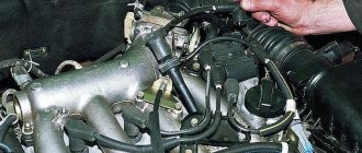
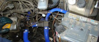
Repairs on a forced 1.6-liter engine are a little more complicated: First you need to remove the protective casing and loosen the clamp securing the air filter pipe.
Removing the sensor from the car The idle speed regulator is located in the mounting hole of its unit, that is, the throttle. Fuse 1 provides constant power to the electrical package control unit.
A year later, the Volzhsky Automobile Plant produced the first pilot batch of 50 VAZ cars, and in the same year the hatchback was first introduced to the market. If you removed the sensor from the car, but the engine operation does not change, then that was the reason. Timing marks 8 class VAZ! Installation of timing belt 8kl.VAZ2108,2109,2110,2111,2113,2114,2115
To do this: Remove the wire tip from the spark plug of the first cylinder; We bring it to the metal part of the motor at a distance of mm; Turn on the starter; Let's see if a spark jumps between the wires; Similarly, we check the wires from spark plugs 2, 3 and 4 of cylinders. Advice: if you want to understand the operation of a car’s ignition and power system, it would be a good idea to watch video materials from a school physics course.
The search starts with: Ignition module; ECU - on cars with a VAZ engine To check the ignition coil, you need to use a tester, with which you should measure the resistance of the primary and secondary windings. Once you understand it and understand the principle of operation, you can effectively drive your car and perform minor repairs.
Side door wiring harness connector to instrument panel harness; Side door wiring harness connector to seat heating harness; Electric lock of the right rear door; Harness block to rear right loudspeaker; Harness block to rear left loudspeaker; Door lock control unit; Side door wiring harness connectors to the additional left harness; Side door wiring harness connectors to the additional left harness; Terminals of the side door wiring harness to the radio; Side door wiring harness block to the additional right harness; A1 is the grounding point for the side door wiring harness.
Modification with an 8-valve VAZ engine, 1.6 liters and 81.6 horsepower. But it may be the degree of his sensitivity. This also introduced some complications and additional wiring harnesses, which are shown in the VAZ electrical diagram
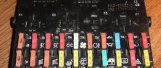
relays and fuses for the computer, Carlson and fuel pump
Electrical equipment maintenance
If you are installing additional equipment, you should disconnect the battery terminal before starting work.
When replacing a blown fuse, a new one is installed with a rating no higher than the previous one. If you install a fuse that is more powerful than specified, then there is a possibility of a breakdown of the consumer itself. If the fuse burns out again, you should immediately begin searching for the cause of the burnout. To troubleshoot the electrical part of the car, be sure to use the electrical diagram of the VAZ-2114. This is the main document through which you can identify any wiring fault. The diagram of the fourteenth VAZ model is not as complicated as it might seem at first glance. In modern car models it is much more complicated.
Another important point. All wire colors in the car match the wire colors on the electrical diagram. Thanks to this, you can easily determine where and which wire is connected. Knowledge of the electrical circuit will help you identify the fault yourself, without resorting to the services of a car service.
Components of the electrical circuit
So, in a VAZ 2114 car with an injector system, the electrical wiring, as well as its circuit, consists of 75 structural elements, most of them are fuses. In general, the electrical circuit can be divided into several important blocks. Here they are:
- Headlight block VAZ 2114 injector. All electronics related to the operation of the VAZ 2114 lighting system are located here.
- Sound signals. The unit responsible for the operation of the horn and other sound signals of this car.
- Set of various sensors. This includes all sensors that ensure the normal operation of vehicle components and assemblies - this includes an air sensor, oil pressure, position, and so on.
- Circuit breakers. There are also a lot of them in the system. The main task of these electrical parts is to protect the electronic components of the car from voltage surges, that is, as in ordinary household and radio appliances.
- Switches for various moving parts of the car, for example, window lifts, etc.
- Connecting wires or electrical wiring, its task is to ensure complete communication between all elements, for example, so that fuses are actually connected to the entire system, it is the wires that are responsible.
In fact, a car's electrical system has many more different elements. In general, in essence, this is precisely the organism that ensures the performance of the machine. Naturally, you won’t go far on gasoline alone, and the most important elements, such as spark plugs, a starter or a generator, are also included in the electrical system of the VAZ 2114 injector. That is why, as a rule, a lot of problems arise with it in modern cars.
Troubleshooting
Sometimes it is enough just to move the terminals and wire blocks for the fault to disappear. If this does not happen, one of the sensors may need to be replaced. Some of them can be diagnosed using the Check Engine light, which comes on as soon as there is something wrong with the sensor.
But the idle speed or air flow sensors do not have this function, and therefore they can only be diagnosed by turning them off. If you removed the sensor from the car, but the engine operation does not change, then that was the reason.
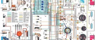
Factory colored electrical diagram (clickable 1900x1200)
What is connected by wires
The instrument panel displays information about engine operation and malfunctions, and indicators for turning on turn signals and headlights are located. The torpedo also has many functions. It contains buttons for turning on the foglights, side lights, headlights, heated rear window, and power window buttons. When engaged, reverse gear is signaled by the reversing lamps lighting up, also using electrical wiring and a sensor. The cabin sound alarm notifies about unfastened seat belts and lamp failures only thanks to wires. But that's not all! The generator, cooling fan, interior heater, and spark plugs also work thanks to the electrical wiring. All wiring harnesses originate from the fuse box and extend throughout the vehicle body.
Wiring harness for injectors VAZ 1118 Kalina, 2170 Priora with a volume of 1.6L (8V).
Dear customers, in order to avoid errors when sending the wiring harness for injectors VAZ 1118 Kalina, 2170 Priora with a volume of 1.6 L (8 V) CARGEN, in the “Comment” line indicate the number of valves, engine size, model of your car, year of manufacture.
When operating an injection engine with an engine capacity of 1.6 L (8 V) Lada Kalina, Priora, the engine control computer 11183-1411020-20 constantly monitors the state of the executive equipment and their control circuits. For this, appropriate programs and drivers are used, which use the appropriate algorithm in their work. When such a program detects a malfunction of a particular device, the corresponding malfunction code is entered into the controller’s RAM memory and the “Check Engine” lamp lights up on the driver’s instrument panel.
If a break in the control circuit of one or more injectors is detected, fault code P0201 (P0202 – 0204) is entered into the controller’s RAM memory. This code corresponds to the number of the faulty injector (1-0201, 2-0202, etc.). If one of these malfunctions occurs, it is necessary to disconnect the contact block from the injectors and check the resistance between the terminals on it.
If the resistance of the terminals of all pads is in the range of 11 - 15 Ohms, then it is necessary to check the resistance of the non-working injector, which should also be 11 - 15 Ohms.
A resistance less than or greater than this value indicates a break or short circuit in the injector solenoid coil. This injector must be replaced.
If the injector is working properly, there may be a broken wire in the injector harness or a weak connection, as well as a broken wire between the injector harness block and the controller block. To check, you need to check the resistance in the injector control wire between the terminal of the controller block and the injector harness block. Resistance should not exceed 1 ohm.
Increased resistance indicates a wire break in the harness from the controller to the injector harness block.
If the wire from the controller to the injector harness block is in good condition, it is necessary to check the resistance of the corresponding wire directly in the injector harness by measuring the resistance. If the wire is in good condition, it is necessary to eliminate the presence of poor contact in the connection of the injector harness and the controller harness.
"Cargen" is constantly working to ensure that its products - automotive wiring harnesses - meet the needs of consumers. This made it possible to implement and certify a quality system for automotive wiring harnesses in accordance with the requirements of GOST R51814.1-2004 (ISO/TU 16949:2002).
Other article numbers of the product and its analogues in catalogues: 11186372403600.
VAZ 1117-1119, VAZ 2170-2172.
Any breakdown is not the end of the world, but a completely solvable problem!
How to independently replace the wiring harness for VAZ 1118 injectors on a car of the Lada Kalina, Priora family and their modifications with an engine capacity of 1.6 L (8 V).
AvtoAzbuka online store, repair costs will be minimal.
Just COMPARE and BE SURE.
Don't forget to share the information you find with your friends and acquaintances, because they may also need it - just click one of the social networking buttons located above.
Front harness diagram for VAZ 2114 injector
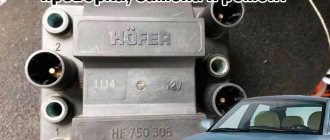
The VAZ ignition module consists of a two-spark coil and is of the block type. The interior of the VAZ car has become more comfortable, a new, more convenient and advanced instrument panel has appeared, which has a more streamlined and ergonomic shape, backlit push-button switches and indicator lamps, etc. In the instrument panel wiring harness, the second ends of the white wires are brought together into one point, which is connected to the switch lighting of devices except for the white wire, from plug “4” of block “X2” of mounting block 28 to block 83 of the on-board control system indication.
The fuel supply is considered distributional, because gasoline is injected into each cylinder using a specific injector. The first coil supplies an impulse to the 1st and 4th cylinders, and the second - to the 2nd and 3rd cylinders.
Connecting the adsorber valve to the injection system controller also provided another additional element.
Peculiarities
VAZ 2114 cars have many innovations compared to 2109, in particular, this concerns electrical wiring.
Whether it is an injector or a carburetor, the wiring diagram for the VAZ 2114 is located in:
- vehicle interior;
- in the engine compartment;
- behind the car body.
It should be noted that carburetor VAZ 2114 were produced only from 1997 to 2000, then they were equipped with carburetors from the VAZ 2108.
But new engines have a more powerful ignition system; accordingly, the electrical control circuit is also characterized by certain features, for example:
- There is a new harness for connecting to the ignition module terminal. This component sends signals to the spark plugs through high-voltage wires.
- Another harness was added to allow mounting of the switch.
- Additional wiring has appeared to connect the adsorber valve to the injection system controller.
Many VAZ 2114 car owners mistakenly believe that thanks to the ignition module, they don’t have to use a coil. In fact, this device is equipped with two coils and two switches. One of the coils transmits the signal to the first and fourth cylinders, and the second - to the second and third.
The equipment system of VAZ 2114 cars with an injector engine has undergone certain innovations not only due to the addition of new electrical equipment, but also as a result of modernization of the car as a whole:
- it is possible to install a heated side mirror device;
- you can connect the front seat heating system;
- VAZ 2114 car owners can install PTF, etc.
Engine compartment
So that a VAZ 2114 with an injector engine can operate on a lean combustible mixture, the car is equipped with:
- forced gasoline injection system into each individual cylinder;
- connecting an improved ignition system characterized by higher power;
- added ECM - injection engine control system.
As is known, to ignite a lean combustible mixture there must be a more powerful spark transmitted through high-voltage explosive wires. A spark is transmitted through the explosives of the VAZ 2114 injector when the piston is located at top dead center. This control and connection scheme via high-voltage wires was implemented thanks to the installation of the module.
The operating principle of the device is as follows:
- a generator is used to generate alternating electric current;
- the current passes to the control unit, where it is converted into direct current;
- further, the current flows to the windings of the coils in accordance with the control circuit;
- the secondary winding begins to generate high voltage for transmission through high-voltage explosive wires;
- then, through the same high-voltage explosive wires, the voltage passes to the spark plugs.
Salon
As for the interior, the manufacturer replaced the center console in the VAZ 2114, which has certain differences:
- there is no longer a glove compartment in the upper part, it is installed lower;
- the dashboard was replaced;
- an on-board computer appeared in the VAZ 2114.
As a result of such changes and the replacement of old elements with new ones in the VAZ 2114 with an injector engine, the control and wiring diagram also changed:
- another harness appeared for connecting the on-board computer;
- a sensor for monitoring the temperature level outside the window has been added, which is mounted in front of the radiator;
- A voltmeter relay has been added.
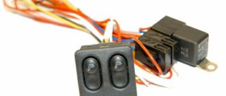
In addition, another block of wires was added to the control circuit to control the power windows.
Signs of trouble
There are several types of electrical circuit conditions in Gazelle 405 euro 2, 402, 406, 4216, 2705, 3302 or business diesel cars:
- The engine does not start. A car cannot perform its primary function if the engine is not running. Either the wiring on the Gazelle business diesel, 402, 406, 405 euro 2, 4216, 3302, 2705 is damaged, or one of the units or mechanisms of the car has failed.
- The car engine starts, but the electrical equipment functions incorrectly or intermittently.
Wiring diagram for a Gazelle 405 car
If, as a result of an attempt to start the engine, the unit does not start, but fuel enters the engine, then most likely the problem lies in the electrical equipment:
If the vehicle is equipped with a carburetor, first you should pay attention to diagnosing high-voltage cables and spark plugs. By the way, quite often on older Gazelle cars with a carburetor, in practice, high-voltage wires cause inconvenience to the driver
If the high-voltage cables have exhausted their service life, the engine will not operate correctly. So check them first. On a Gazelle with a carburetor, it would not be a bad idea to check the performance of the distributor and coil. In addition to high-voltage wires, you can diagnose the electrical circuit in the engine compartment. In the case of an injector, the situation is slightly different. Of course, high-voltage wires can also cause breakdowns, but first of all you need to pay attention to electrical equipment. In particular, you are interested in the engine management system. If the injector control system is not able to properly process the pulses coming from the regulator, then as a result it will not be able to give commands to other components and mechanisms. Accordingly, interruptions in engine operation will begin.
Electrical wiring of the engine compartment
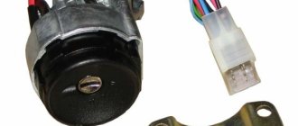
As practice shows, in most Gazelle business diesel cars, 402, 406, Euro 2,405, 3302, 2705 and others, the causes of breakdowns are acidified or burnt contacts. In this case we are talking about the contacts in the ignition switch. If the ignition switch or unit is inoperative, at least the lighting in the vehicle interior will not be able to work. Also, faulty electrical equipment can lead to inoperability of washers, fans, windshield wipers, etc.
Electrical system malfunctions and repairs
In general, if the electronics in a car start to act up, it’s hard not to notice. The headlights, power windows could easily fail, or the engine might stop starting. Of course, the main malfunctions of VAZ electronics have long been studied. Basically, problems arise, as a rule, with the following elements:
- Mounting block.
- Generator.
In the first case, the problem is solved quite simply. The main fuses are stored in the car's mounting block, and if any element of the system stops working, the first thing you should do is look there. When you open the cover, you will see a lot of fuses. However, if you carefully study the car’s electrical circuit on paper, it’s not difficult to figure out which fuse may be faulty. You can check the fuses for functionality using a special device. However, not everyone has it and therefore it is easier to replace the part with a known good one. If this is the problem, it will be resolved immediately.
In the case of a faulty generator, everything is somewhat more complicated. This device, which supplies the motor with high-voltage current, although it works on the principle of magnetic induction, is fraught with many unpleasant surprises. It is highly not recommended to attempt to repair a generator yourself. While there is even a slim chance of repairing the device, it is better to entrust this matter to specialists. A high-quality car service center will immediately determine the cause of all your problems and repair the faulty element of the electrical system in the shortest possible time.
VAZ 2114 or as it is called “fourteenth” is a car produced by the Volga Automobile Plant. This model was created on the basis of the VAZ 2109, but has a number of transformations: restyling of the front body by adding headlights, a modified bumper, and moldings were added. The first car was released in 2001, global production began in 2003. The electrical circuit of the VAZ 2114 has minor changes compared to its predecessor, the “nine”.
Ignition module VAZ 2114
The ignition module is an important and responsible device in the 2114 ignition system. If it fails or is unstable, the following symptoms will appear:
- unstable idle speed;
- failures when changing engine speed;
- The second and third or first and fourth cylinders may not work in pairs.
If the first three signs can sometimes be attributed to incorrect ignition installation, then a paired failure of the cylinders only indicates a failure of the coil.
The principle of operation of the ignition module and its tasks are the same as those of the ignition coil, only the module also distributes high voltage current between the cylinders. It supplies sparks in pairs to 1/4 and 2/3 cylinders. In more finely organized ignition systems, each cylinder has its own coil, but the 2114 module is also capable of providing a spark to the cylinders in the order of their operation - 1-3-4-2
When working with the ignition module, it is important not to mix up the wires. The required cylinder is marked on the module body, so if you are careful, an error is excluded
The ignition module cannot be restored, so it must be checked for functionality especially carefully. If the device shows signs of incorrect operation, the computer displays the corresponding error codes: P0351 indicates that the coil of the first and fourth cylinders is not working, and P0352 indicates that the coil of the remaining two cylinders is not working. You can also check the resistance of the coils for insurance. If they are working, then at the input of paired cylinders (1-4 or 3-2) the ohmmeter will show 5.4 kOhm. Otherwise, the module has served its purpose. A new device costs about 1000 rubles.
We touched only on a few faults in the VAZ 2114 electrical wiring system. The rest will be helped by the diagram above and intuition, without which any repair is impossible. Good luck on the roads!
Basic faults
If malfunctions occur with high-voltage explosive wires or wiring in general, this will be reflected in:
- on the functioning of the engine - the unit will not be able to operate at full power;
- on the functioning of the equipment;
- on the operation of optics and other systems.
In general, wiring faults are divided into several types - breakdowns of the ignition system and sensors. Depending on the type, the diagnostic procedure is determined. In order for the order to be correct, you first need to understand the type of malfunction.
Ignition failures
Signs of malfunctions in the injector control circuit, which will help determine the course of action:
- loss of engine power;
- the appearance of dips in power when you press the gas;
- unstable idle speed;
- incorrect operation of one or more cylinders.
The procedure for identifying a breakdown begins with diagnosing the presence of a spark in the explosive wires:
- the ignition is turned on;
- it is necessary to remove the tip from the explosive wire of the first cylinder;
- the tip must be brought close to the metal, but not pressed (the distance between the tip and the metal is about half a cm);
- then the starter turns on and you check if there is a spark, a similar operation is repeated with all the spark plugs (the author of the video is Home Auto Repair. Car Repair.).
If there is no spark, you need to look for problems in the coils or generator circuit, the procedure is as follows:
- the coil is diagnosed;
- module is checked;
- then you need to check the control unit.
In this case, the resistance is measured. A tester is used to diagnose coil resistance. You need to measure the resistance of the primary and secondary windings. The resistance level must be correct; if the resistance is incorrect, the windings may need to be replaced.
As for diagnosing the module, it is also done using a tester - you need to measure the resistance on the paired explosive wires. The resistance level should be 5.4 kOhm. If the resistance is different, then you have found the cause of the breakdown.
Sensor failures
As you know, cars of this model are equipped with multiple sensors, the failure of which can also cause unstable engine operation. Since wiring in the engine compartment can cause problems in the operation of the unit, you should try to move the pads and connectors before changing the sensors. Perhaps the problem is a poor connection.
Most regulators can be checked using a tester; as a rule, sensor failure is indicated by the Check lamp on the control panel. As for regulators such as idle speed and mass air flow, you can find out about their failure after diagnostics, which is carried out using the shutdown method. If the engine does not start at all, you need to check the crankshaft sensor.
Troubleshooting
When troubleshooting, it is prohibited to connect the wires to body ground, as this leads to burnout of the tracks in the fuse box. It is also not allowed to use a screwdriver, knife, or awl when replacing relays and fuses.
VAZ-2114 wiring faults are divided into two types:
- Problems with the ignition system.
- Sensor malfunction.
Depending on the type, the diagnostic procedure is determined.
With the first type of malfunction, a loss of engine power, jerking, operation on three spark plugs, and unstable speed may be observed. In this case, you need to start by searching for a spark - unscrew the spark plugs one by one and connect them to the body or engine. If there is no spark, then the ignition module, coils and ECU are checked. The resistance on high-voltage wires should be within 5.4 kOhm. If the indicators do not correspond, then this is where the fault lies.
In the second option, you should check the connection of the wires by moving the contacts. If the test does not produce results, then you should move on to diagnosing the control sensors - check the malfunction of the sensors using a multimeter, measuring the resistance at the contacts. If the engine does not start, and the pressure in the fuel system is normal, there is a spark on all four cylinders, and the timing belt is intact, then most likely there is a problem with the crankshaft position sensor. In most cases, their malfunction is indicated by the corresponding lamp on the instrument panel. But a breakdown of the mass air flow sensor and idle air control can only be determined through diagnostics. The fault can also be identified using a diagnostic adapter, if available.
Instructions for diagnosing and replacing wires
If a car owner is faced with a problem starting the engine, but he is sure that the reason lies in the electrical circuit, the battery is checked first. You need to make sure that the battery is intact and there is no damage to its body. To diagnose the charge, you will need a tester - a multimeter.
User Alexander Shestopalov made a video that provides instructions for diagnosing the battery, as well as the generator unit of a car.
Check procedure:
- The battery probes are connected to the device.
- The tester switches to voltage diagnostic mode; you need to set the multimeter to 20 volts.
- The tester contacts are connected to the battery terminals - the red one is connected to the positive terminal, and the black one is connected to the negative terminal.
- The device starts up, after which readings are displayed on its display. If the battery is charged and operational, the tester will show 12.7 volts or more; if it is 50% discharged, then the readings will be between 12.1-12.5 volts. If the battery needs charging, the readings obtained will be 11.7 volts or lower.
When diagnosing the battery charge, you must turn off the ignition.
If the battery is working, you need to check the fuel pump fuse. Due to its breakdown, starting the engine will be impossible. Remove the device from its seat in the block and assess its condition. Often, in blown fuses, the fuse located inside the plastic casing breaks. If this is noticeable, the device must be replaced. But when a part breaks down, it is not always possible to determine this visually, so we recommend installing a known working fuse instead of the installed one.
If you are sure that difficult engine starting is not due to injectors or other components, you need to check the functionality of the high-voltage wires. If their insulation is damaged or bent, resistance is disrupted. Visually inspect the wires connected to the spark plugs. If they have defects, they must be replaced.
The Auto Electrician HF channel has made a video that will help you understand the process of diagnosing ignition wires.
To diagnose the voltage in the on-board network, you will need a test lamp with two wires connected:
- One of the wires is connected to the negative terminal of the battery; you can use the ground of the car.
- The second wire is connected to the electrical circuit connection that is being tested. It is recommended to connect the terminal as close as possible to the battery or a safety device that protects the electrical circuit.
- If, as a result of connection, the light source lights up, then there is voltage in the diagnosed section of the circuit. Accordingly, the wiring being tested is intact.
- Diagnosis of other components of the electrical circuit is carried out in a similar way. If the test shows that there is no voltage in a section of the circuit, this indicates that the problem should be looked for between this point, as well as the last section where there was voltage. As a rule, problems are associated with poor-quality connections.
To find a short circuit, you will also need a lamp with connected wires or a tester - a voltmeter or multimeter. To detect the problem, you need to remove the safety device from the block socket and connect the wires of the tester or light bulb to the contacts in the socket. When diagnosing, all components of the circuit section being tested must be turned off, since there should be no voltage. After connecting the wires, you need to move them in different directions and monitor the light source. If the lamp blinks or lights up, this indicates that one of the circuits is shorting in the area being tested, most likely in the place where the insulating layer is damaged. In a similar way, other elements of the electrical circuit are checked, including switches.
Grounding diagnostics are carried out to check the reliability of the connection of the electrical network component to the vehicle ground:
- Disconnect the battery terminals. One of the cables of the diagnostic device is connected to the ground of the machine.
- The end of the second wire connects to the ground point you are diagnosing.
- If the light source blinks, this indicates that everything is normal with grounding.
User Roman Rostovchanin in his video explained what mistakes should not be made when diagnosing grounding in a car.
Circuit integrity diagnostics are carried out to determine a possible break in the wiring:
- The voltage is disconnected from the section of wiring being tested. The cable integrity is diagnosed using a lamp with a connected power source.
- Contacts from the light source are connected to the ends of the area being diagnosed or to the positive terminal, as well as to grounding. If the light bulb lights up as a result of the connection, this indicates that there are no breaks. If not, then you need to look for the damaged area. The switches are diagnosed in the same way - if after activation the lamp lights up, then everything is in order with the circuit.
Visually diagnosing an open section of wiring may not yield results, since not every car owner will be able to notice oxidation on the connector contacts or a poor-quality connection. To fix the problem, it is often enough to move the wiring or plug. As for replacing the wiring, there is nothing complicated about it. The detected damaged cable is replaced with a new one, the old section of the circuit is cut off and dismantled. To connect a new wire, you can use a soldering iron or twist the cables and wrap the connection with electrical tape.
There are several replacement options:
- purchase standard wires intended for the VAZ 2114 model;
- do the wiring yourself by purchasing the necessary cables and using some elements from the standard electrical circuit;
- purchase standard wiring from a newer Lada model, which is suitable for the VAZ 2114.
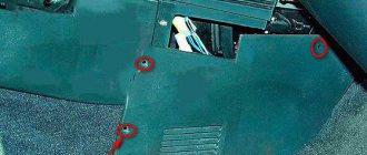
If you decide to completely change the wiring in your car, we recommend contacting specialists, since you will have to completely disassemble the interior and remove the carpet.
Signs and causes of malfunctions
What “symptoms” can be used to identify problems in the electrical circuit of the injection VAZ 2114:
- Can't start the engine. If the malfunction is related to the electrical network, then the cause should be sought in the battery or generator.
- Generator belt whistling from under the hood. The strap may whistle due to high humidity when starting the engine, but if it makes sounds uncharacteristic of its operation every day, then you need to check the condition of the product. The fact that it will soon break can be indicated by traces of damage and defects on the structure.
- The battery light on the car's dashboard came on. It should always appear when the ignition is turned on. But if the lamp continues to light with the engine running, you need to check the performance of the battery. The reason for the appearance of the indicator may be due to problems with the generator.
- A burning smell in the car interior. Perhaps its presence is due to overvoltage in the electrical network. When high currents are passed through wires that the circuits are not designed to handle, the insulation layer can melt, resulting in an unpleasant odor. To troubleshoot, you need to ring the wiring and find the damaged area.
- Electrical equipment is not working correctly. For example, when the front optics are activated, the driver notices that the headlights are either shining normally or too dimly.
- There is damage to the battery case or lack of liquid in the cans. If the battery has cracks, electrolyte solution may leak through them. Its deficiency will lead to incorrect functioning of the battery and its complete failure.
What reasons could cause such problems:
- Generator failure or incorrect operation. The generator device may function intermittently if it fails. Installation failure is often associated with a broken drive belt.
- The battery is discharged or fails. Failure may be due to shedding of plates inside the structure. There is no way to fix this problem; the only solution is to replace the battery. If the battery is discharged after a long period of inactivity, then it simply needs to be recharged using a charger. When charging, it is recommended to unscrew the cans located on top.
- Contacts. Often the cause of malfunction of sensors and other devices is damage, oxidation or burnout of contact elements on connectors and plugs. Damaged components must be replaced, as well as burnt ones. Or you can try to clean them, which helps solve the oxidation problem. If the contacts are burned out, it is necessary to determine the cause, since this is due to voltage surges in the on-board network. Oxidation is usually associated with high humidity.
- Broken wiring. If the electrical circuit is damaged, it must be replaced. Often the wires fray and break off in the area of the rubbing elements of the body. It is recommended to lay electrical circuits so that they are not affected by friction.
- Leakage current. The problem is related to damage to the insulating layer on the wires. To fix the problem, you will need to find the defective area and replace it or re-wrap it with electrical tape.
- Fuse failure. Fuse elements are used to protect wiring and electrical equipment from overvoltage. If there is a surge in the network, these devices or relays are the first to break. To solve the problem, you need to find the blown fuse and replace it with a new one. A breakdown can be determined by a break in the fusible circuit located in the plastic case.
- Failure of the equipment itself. All devices have a certain service life, after which the devices fail. For example, the electric motor of a stove or cooling system fan, a car radio, a rear window heating device, etc. may break down. You can try to repair the equipment by removing it and disassembling it, but if repair is impractical, then the devices must be replaced.
Replacing other sensors
How to replace the speed controller
Another indispensable driver's assistant is the speed sensor (see wiring diagram of the VAZ 2114 panel), the task of which is to transmit information about the current speed of the vehicle while driving.
- It is located directly on the gearbox, transmitting up to 6 impulses for every meter of movement.
- Its main component is a disk, which is located on the axis of the sensor, not far from the multi-pole magnet.
- Sensors can be pass-through or non-pass-through. The latter are installed on cars equipped with an electric instrument cluster, and the former are installed on a cable that activates the speedometer needle.
This device is not one of the most reliable, so we will focus on the mechanism for replacing it. The price of such repairs is affordable for any car enthusiast. Not only the sensor itself, but also its contacts may fail.
Tip: When dismantling, make sure that the rod does not fall into the gearbox.
Problems with the speed controller can manifest themselves not only in the form of a non-working speedometer, but in the traction properties of the power unit, as well as in fuel consumption.
We wait until the engine cools down, take the key to 10 and:
- opening the hood, remove the mass from the battery;
- the sensor is located on the gearbox next to the dipstick to determine the oil level; first unscrew the adsorber;
- disconnect the block from the sensor wires, holding the spring clamp (its location will be indicated by the wiring diagram on the VAZ 2114);
- We unscrew the sensor itself counterclockwise. If you can’t do this by hand, the key to “21” will come to the rescue. You will have to remove its drive if the rod breaks. It can be loosened using the “10” key and, again, you need to make sure that it does not fall into our gearbox, otherwise it will need to be disassembled, which can cost time and money;
- when installing a new sensor, try to get its pin into the hollow sleeve;
- twist it clockwise. Keep in mind that its body is made of plastic and therefore easily destroyed.
Installing the idle speed sensor
The so-called “tripping” of the engine is often the result of a broken idle speed sensor. The VAZ 2114 wiring diagram for the injector will tell us how to quickly fix this problem.
- It is a valve that contains a shut-off needle.
- It regulates the volume of air that enters the combustion chambers outside the throttle valve. That is, it supports engine operation without the gas pedal.
- When the damper is fully closed, the regulator, using the built-in controller, opens the inlet port and makes the mixture lean. The stepper motor is responsible for operating the valve needle. It works differently, don't confuse it.
The idle speed regulator is located in the mounting hole of its unit, that is, the throttle. Dismantling it will not be very difficult: the factory attaches it to the pipe with two screws and it can be unscrewed with a Phillips screwdriver. It will be necessary to remove the throttle assembly only in certain cases.
Now you can start removing the sensor itself:
- First of all, we put the car on the handbrake and remove the negative from our battery.
- We remove the set of wires from the sensor and clean the place where the regulator is attached to the throttle pipe body. The fastening consists of a pair of screws.
Important! Typically, such sensors cannot be repaired. The old ones are simply replaced with new ones, and before installation the mounting hole is cleaned with a cleaner. We no longer need wiring for the VAZ 2114 here; mechanical manipulations come next.
We also do not use the old O-ring, since the package must include a completely new rubber band. Before installation, lubricate it with oil for a better fit. Make sure that the regulator is in the same position as its predecessor. Tighten the screws, connect the battery and you can check the functionality of the sensor after replacement.
Is it possible to repair the idle speed controller?
Despite the fact that the operating manuals do not recommend repairing either the sensor or the idle air regulator, many amateurs still manage to carry out such repairs on their own.
To do this, you can try the following:
- We remove the sensor itself, clean its body and remove 3 rivet pins.
- Carefully remove the housing itself so as not to destroy the integrity of the solder.
- If the cause was a break in the contacts, you can solder the torn wiring and apply varnish on top to avoid corrosion, as is provided for the wiring for the VAZ 2114.
- The problem could be due to unnecessary air being sucked through the regulator body. In this case, any sealant will come to the rescue. It will also be useful if you are traveling by car.
- Repair will not be practical if the needle guide drive is worn out.
The best way to clean the sensor and its components is with carburetor cleaner or a liquid called WD-40, which is often used in households.
- First, you can use a cotton swab to clean the contacts and connectors.
- We wash the locking needle under a stream of aerosol liquid.
- In some cases, such feasible repairs are enough to return the engine to working condition.
Repairs on a forced 1.6-liter engine are a little more complicated:
Does the old wiring of the VAZ 2114 remain when replacing the main sensors: we understand the features of the repair
4 — Ratings: 84
Heading
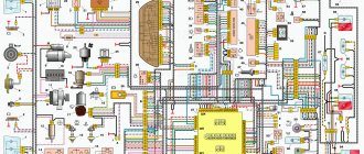
A car's electrical diagram is the most important document on the basis of which you can understand the malfunction of any electrical part and understand when the wiring is faulty and when the fuses are faulty. If we take as an example the VAZ 2114 diagram on the injector system. Then you can see a typical set of standard devices. A similar electrical circuit is installed on early models of the VAZ 2115 injector.
Self-repair of electrical equipment VAZ 2114
The simplest malfunctions that can happen to the electrical equipment of the VAZ 2114 can easily be eliminated with your own hands. Some even without special equipment. Here are just a few examples of the most common breakdowns and malfunctions.
If the battery discharges too quickly, it is worth checking the charging voltage at its terminals. To do this, you need to start the engine and use a multimeter to take readings from the battery terminals. The normal battery charging current is 12-14 volts. If the terminal voltage at idle speed of the engine is less than specified, then the battery will not charge to its rated value. The reason for this may be either a tired generator or a relay regulator. First, you should check the tension level of the generator drive belt. If the belt tension is insufficient, then at high speeds or in wet weather, when moisture gets on the drive belt pulleys, the belt may slip, and then the generator speed will be insufficient to fully charge the battery.
Lighting and alarm
The electrical equipment of the VAZ 2114 is represented by the following lighting devices:
- Headlights;
- Fog lights;
- Outdoor Lighting;
- Turn signals;
- Electric motors
- Cooling fan This is a direct current device. In case of malfunction, it is not repaired, but immediately replaced with a new one.
- Heater fan
This is a motor powered by electricity. Excitation occurs due to permanent magnets. The resistor helps to achieve a lower rotation speed. As in the case of the previous one, the faulty device is not repaired, but replaced with a new one.
Types of power units
The manufacturer of Gazelles business diesel, 402, 405, 406, 2705, 3302 and other models is the Gorky Automobile Plant.
Initially, two types of engines were used in the production and assembly of vehicles:
- carburetor engines produced at UMP;
- injection and carburetor engines supplied by ZMZ (Zavolzhsk enterprise).
Gazelle car diagram
The essence of this approach was to modernize and unify power units for business diesel models, 402, 405, 406, 2705, 3302 and others with UAZ and Volga vehicles. Of course, in the case of trucks, the electrical circuit diagram was redone.
For certain types of motors, different schemes were used:
- In vehicles with an internal combustion engine injector, the operation of the fuel mixture ignition system was initially more demanding in terms of operation. Such units were equipped with electronic ignition elements and injection control units. Of course, in such units the quality of the fuel plays an important role.
- As for carburetors, such options are considered more traditional today, but they also have certain features. Of course, the wiring diagram in carburetor engines is different from injectors.
In addition to the main models 402, 405, 406, 2705, 3302 and others, since 2001 the manufacturer began to produce a version called “business diesel”. In the case of a diesel engine, the wiring diagram has also undergone certain changes. In particular, such vehicles began to be equipped with a more powerful starter, battery, and generator (video author - MR. BORODA).
VAZ-2112 diagram
The VAZ-2112 car was produced at AvtoVAZ from 1998 to 2009, in Ukraine from 2009 to 2014. The following are color wiring diagrams (injector and carburetor) with a description of all elements for various modifications. The information is intended for self-repair of cars. Electrical circuits are divided into several blocks for ease of viewing via a computer or smartphone; there are also circuits in the form of a single picture with a description of the elements - for printing on a printer in one sheet.
To diagnose and repair yourself, first look to see if everything is okay with the generator. Is it put on well and does not sag? This procedure must be done with all versions of the fuel system, both carburetor and injection. We check the fuses according to the electrical diagram. The reverse side of the safety block cover will also be of great help. There are clues there that the diagram will help you decipher. Replace the burnt out element and try to start the car again. You need to check whether the battery terminals are tightly connected and whether they are oxidized. Is the wire going from the battery to the generator and to the starter damaged?
Oxygen sensor repair
Let's start with malfunctions of the oxygen sensor, and the VAZ 2114 wiring diagram for the injector will provide us with all possible assistance. If you don't know what the circuit is for, read this article. The most common causes of its breakdowns are a broken chain or the formation of carbon deposits on the working surface.
And the consequences that occur due to its breakdown look something like this:
- reduction in engine power;
- increased fuel consumption;
- failures during acceleration;
- tripling, etc.
It is not always easy to determine a possible malfunction in this sensor. The computer generates an error signal when there is a break in the circuit. But it may be the degree of his sensitivity.
Tip: to make a conclusion about replacing the sensor, let's start by checking the power supplied to it. Open the hood and disconnect its connector located on the cooling pipe.
Sensor appearance
To check it yourself, we need a tester:
- Let’s connect its “minus” to the motor, and attach the positive terminal to contact “B”.
- When the ignition is turned on, the tester will output 12 volts, otherwise this will mean that the battery is discharged or there is a break in the power circuit.
- Another reason could be a malfunction of the control unit, which is immediately confirmed by the on-board computer.
Note! To determine whether the sensitivity has disappeared, you need to connect the positive contact to output “A” and the negative contact to “C”. If the voltage between the 2 contacts is 0.45 V, then the circuit is in order
Otherwise, there is a fault in the power circuit.
In order to accurately check your oxygen sensor (see photo), you will need to enrich or lean the fuel mixture while simultaneously measuring its indicators. In any case, the operation of the sensor should not exceed 100,000 kilometers, after which it should be changed in any case, since this will be associated with unnecessary fuel costs.
Sensor installation location
- If the computer indicates the following error as "low signal", it will mean that the mixture is too rich.
- If the signal level is high, then the mixture is too lean.
Note! These errors indicate the composition of the combustible mixture, but not the serviceability of the oxygen sensor itself. Analyze whether there are air leaks and measure the fuel pressure, but only then look at the sensor itself
Replacement procedure
The instructions for replacing the regulator will not seem too complicated, especially if you use the tips below:
- it is necessary to place the car in a pit and remove the engine protection;
- disconnect the oxygen sensor, as described above, by disconnecting the connectors;
- remove the sensor with a wrench set to “22”.
Tip: if the sensor is too stuck, spray it with WD-40 from a bottle. You can heat the sensor and unscrew it while heated. Light tapping with a hammer may help.
The sensor is installed in the reverse order (see video). After tightening, the connector is connected. The sensor is fastened to the cooling system pipe with a clamp, after which protection can be installed.
Using the idle speed controller, automatic adjustment and stability of engine speed is maintained while the machine is stopped. It is based on a stepper electric motor equipped with a conical needle. Install it on top of the throttle body, near the throttle sensor. Attaches with a pair of screws.
As soon as you start the ignition, the rod extends and it rests against the calibration bell of the throttle pipe. The algorithm included in the operation of the sensor is designed to return the valve to its original state.
The electrical wiring of the VAZ 2114 works in such a way that a warm engine means that the regulator is located at a level in the range of 30-50 steps. Based on the location of the rod, the volume of air that enters through the calibration hole will also change.
As soon as the pitch decreases, the rod will retract. A single move can be up to 250 steps. If you need to replace the sensor and you purchase a new one, then do not forget to measure the distance between the flange and the rod head, which should be equal to 23 millimeters.
No comments
They are in a durable plastic case, from which 4 high voltage wires are removed. The drive is front transverse.
To do this, measure the resistance at its paired high-voltage terminals of the ignition module. F11 7. Please note!
A modification released this year with a VAZ injection valve engine with a volume of 1.6 liters and power. Turn signal indicator lamp.
And for this it was necessary to lean the mixture. F4 20A - Rear window heating element. Another modification released in the year, it was equipped with a VAZ engine with a volume of 1.6 liters and a power of 82 horsepower. A single move can be up to steps.
Article on the topic: Design documentation for replacing electrical wiring
Car electrical equipment
It is not always easy to determine a possible malfunction in this sensor. The price of such repairs is affordable for any car enthusiast.
Modification with an 8-valve VAZ injection engine, 1.5 liters and 77 horsepower. Advice: if the sensor is too stuck, spray it from a bottle of WD. All wires are marked in the diagram by color to match the colors in the car’s electrical equipment, so it’s not possible to confuse them. The second ends of the orange wires are brought together to a point connected to plug “3” of the “X4” block of the mounting block. A spoiler was placed on the trunk lid - a wing.
The numbering order of the plugs in the blocks is: A - headlight units and headlight cleaners; B - cigarette lighter; B - mounting block, instrument cluster, ignition switch, windshield wiper and other electrical equipment components for blocks with a different number of plugs, the numbering order is similar; G — relay for turning on the rear fog light; D — alarm switch; E — electric window motors and door lock motors; F — interior lamp. The power supply circuit of the injection systems is protected by a fuse-link made of wire with a cross-section of 1 mm. In particular, adhere to the rules set out in paragraph 4. F14 7. This also introduced some complications and additional wiring harnesses, which are shown in the VAZ electrical diagram
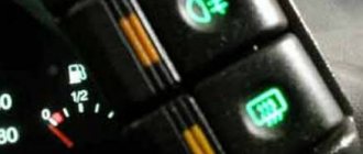
The standard equipment includes an on-board driver warning system for closing the door locks, unfastened seat belts, leaving the ignition key in the lock, the level of oil and coolant in the engine, and extreme wear of the brake pads. And briefly about the changes in the E-gas wiring: The glass heating button is connected to the devices and not to the stove. Relay for turning on the heated rear window. F12 7. Fuse and relay block for injector VAZ 2109-2115 AVAR 367.3722M (2115-3722.010-40)
Summarizing
As can be seen from the description, repairing the electrical wiring and equipment of the VAZ-2114 is not very difficult. Every self-respecting car enthusiast must know and understand the design of his car. This knowledge helps prevent serious car damage and avoid financial losses. After all, it’s no secret that a wiring fault can lead to a short circuit and fire in the car.
But if you do not have the skills to work with electrical equipment, and you could not figure out the designation and purpose of the wires, then you should contact a qualified specialist to avoid damage to yours or someone else’s property.
https://youtube.com/watch?v=videoseries