When removing the gearbox, it is necessary to unscrew the bolts securing the cab floor cover, remove it and unscrew the driveshaft mounting flange
Unscrew the bolts securing the PSU to the bracket, disconnect the pusher from the clutch fork lever and, without disconnecting the pipelines, secure the PSU to the car so as not to damage the pipelines.
Remove the housing with the gear shift lever.
Disconnect the intermediate support bracket from the frame cross member and lower the propeller shaft, disconnect the speedometer shaft.
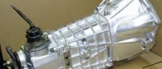
Rice. 5-2. Removing the gearbox from the car using a jack-trolley
Rice. 5-3. Gearbox transport suspension
Rice. 5-4. Tool for assembling and disassembling the gearbox
Unscrew the nuts of the studs securing the gearbox to the clutch housing using a spanner.
Disconnect the gearbox from the clutch housing and remove it using a jack-trolley with a special puller 32P-1270 (Fig. 5-2).
After removing the gearbox from the car, you need to install the crankcase with the gearbox control lever in place.
Before disassembling, it is necessary to drain the oil, remove the plug from the drain hole, then clean and rinse the outside of the gearbox.
Using the suspension (Fig. 5-3), hook the box, lift it with a lift and install it on the device (Fig. 5-4) for disassembling and assembling gearboxes.
Installing the gearbox on the bus is carried out in the reverse order of removing it.
Engine for ZIL. Topic started by Jack
Tell me, will the YaMZ-236 engine fit on the Zil-130 instead of the gasoline 8 and what gearbox and rear axle should I install???
.I just have an idea to build a truck tractor on a long ZIL-130 wheelbase. Andrey (Aias) 100% what will fit if the cab is 131, the original 130 is in question, it’s better to install a MAZ box, and if you find a casing, it’s better to use a KAMAZ box with a divider.
Alexander (Socrates) The ZIL itself was developed. There was even a prototype made on the basis of the ZIL-130. The gearbox is better than KAMAZ with a divider, and the rear axle is either KAMAZ or RABA
Denis (Macario) But won’t your frame burst in a couple of thousand.
Alexander (Socrates) You can consider an option with some kind of Japanese diesel engine. It is lighter than 236, but can be equal in power
Nikolay (Fransis) ———————
Roman (Razanah) used to install diesel engines from the MTZ-80 on collective farms and it works well.
Alexander (Socrates) Engines are still supplied from MTZ (D-240; D-245).
236 also stands up normally if the cabin is a new model.
Sergey (Obayana) Dmitry, my friend did it and it didn’t work out. The 130 is not included, you need the kadin 131 and the lining, but the internal combustion engine needs to be raised above the frame by 6-7 cm and on the springs by 10 cm under the hood there is no room to redo the pan at all, the gearbox is from MAZ, hfostovik high connect to the original axle, the problem is that the cardan has a kink angle of attack of more than 30 degrees, they installed the rear axle with 131 weak, the rear axle from Kamaz was considered, but this porekt ended, they threw everything away and put 240 on the original gearbox and axle, but for the saddle the internal combustion engine is weak, 6 tons, it’s hard for him and also about the Mazda ICE in front of the heavy ass, the driver doesn’t eat a little bit of snow when he climbs, advice - DON’T WORRY
Ruslan (Rayanna)
Ivan (Haruka) Ruslan, the 236 engine will fit, but you need to raise the cabin, or leave the Zilov radiator. But with Zilovsky it is not known how the cooling will be under heavy loads
Alexey (Vanja) How to plant it in the frame, the deeper the better
Sergey (Obayana) Selling 2.0 engine 10 thousand km. mileage, 135 mares, gasoline, with manual transmission, transfer case, all-wheel drive, there is a cardan, gearbox, wires, cams, rocker, pedals, wiring and much more.
Sergey (Obayana) SMD is installed with a DT 75 and a Niva combine harvester. It sings with a turbine but the speed is weak
Ignat (Vikram) great guys, I wanted to know your opinion that if the engine is boiled in a ZIL 130, what could this affect? Tell me, who knows if it’s not difficult
Ignat (Vikram) or is it already junk
Groundhog (Justica) Selling a w124 602 2.5 diesel engine with all attachments. The attachment includes the entire swap kit to install and start, right down to all the pipes, etc., + radiator and exhaust. Price RUB 30,000. The engine is on the car and can be started. city of St. Petersburg
Kirill (Chuki) But the bridge won’t go from punishment, the Mazovsky one will go, it will be as big as a hundred pounds and then there will definitely be a beast
Kirill (Chuki) When you move out of a place, the load goes to the rear, and the Karovskiy won’t withstand such a load; the gear will break under heavy load, so safely put on the Mazovskiy
How does the gearbox of a ZIL 130 car work?
Volkswagen Passat Das graue Auto Logbook Replacing the gear shift cable
ZIL 130 and 131 cars are equipped with a three-way five-speed manual gearbox. The gearbox of this vehicle allows the driver to move forward at five speeds and backward at one. You can find a drawing of the device below. As can be seen in the diagram, the ZIL 130 and 131 gearbox is equipped with two inertial synchronizers, which include the second and third, as well as the fourth and fifth.
The drive shaft, together with the gear and ring gear to activate the fifth (direct) speed, is installed in the crankcase on bearings.
Sectional diagram of the unit with all symbols
Identification of all transmission components
In addition, spur gears are mounted on the cardan, designed to activate reverse (reverse) gear and first gear. Also, activation of these modes is provided by a spur gear and synchronizer components mounted on the splines of the secondary pulley.
In addition, additional gears are mounted on the secondary shaft:
- to engage second gear;
- to activate the third mode;
- to turn on the fourth.
And these gear rings, when operating, are in constant engagement with the wheels mounted on the intermediate disk. The reverse movement unit is mounted on special roller bearings, which are located on an axis in the crankcase. Here they are installed quite securely. The reverse drive cardan also works in conjunction with the idler pulley through additional wheels.
As for the inside of the crankcase, the working fluid is poured here, so this part is always closed from debris and dust. The switching mechanism itself is installed here. It should be noted that the gearbox switching mechanism on ZIL 130 and 131 is designed in the same way as on GAZ 53.
Switching circuit
The switching diagram for the ZIL 130 and 131 gearboxes is presented below. In general, the scheme is original, but if you believe the words of ZILovodov, then you can get used to it very quickly.
How the transmission lever shifts
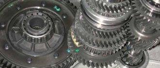
The second stage of manual transmission disassembly
At the second stage, the components of the ZIL-130 manual transmission are disassembled (Fig. 3).
Rice. 3. Gearbox parts:
Rice. 4. Stand for disassembling the transmission drive shaft:
1 – plate; 2 – bolt; 3 – bushing; 4 – gear coupling; 5 – screw
Rice. 5. Device for disassembling and assembling the gear shift mechanism:
According to this technological scheme, the 4th and 5th gear synchronizers are disassembled.
PTO power take-off.
Sequential gearbox for VAZ 2108. Gearbox
Its name hints at the fact that it takes part of the engine torque and transfers it to special mechanisms. This could be a hydraulic pump or a utility equipment attachment. The PTO works in close conjunction with the gearbox, and is activated from the vehicle cabin. A huge amount of load and work falls on this small device.
Power take-off
Therefore, they always strive to make it strong and durable. There are 2 types of PTO, clutch dependent and clutch independent. The first one works when the engine is idling. Dependent PTO is lightweight, easy to install and requires almost no maintenance. They are mounted on a manual transmission and activated by the driver from the cab. An independent PTO can work with both manual and automatic transmissions.
It is installed on concrete mixers, road cleaning equipment, and agricultural machines. The place where the PTO is registered can be a gearbox, transfer case, engine, or the space between the engine and gearbox. KOM is a highly durable unit, but even it can break.
Often, breakdowns are immediately visible; the PTO either stops turning on normally or begins to make loud noise. Problems are solved in different ways, starting with simply tightening the nuts and ending with complete disassembly of the PTO. In any case, without the appropriate knowledge and skills, independent repair of the PTO is not recommended by the manufacturer.
WATCH THE VIDEO
Primary shaft
Primary shaft ZIL-130
The input shaft is made of steel 25 KhGM, the depth of the nitrocarburized layer is 0.6...0.8 mm, the hardness of the surface layer is HRCe 61...66, the hardness of the core is HRCe 37...46.
Basic data on shaft seats, permissible wear of splines, journals and shaft seats for bearings, as well as data on gears.
Thickness of straight spline teeth - 5, 805…5, 855
The diameter of the roller bearing seat is 43.980…44.007
The diameter of the shaft journal for the ball bearing is 60.003…60.023
Shaft end journal diameter - 24.975...24.995
Secondary shaft
Secondary shaft ZIL-130
The secondary shaft is made of steel 25 KhGM, nitrocarburization depth 0.8...1.1 mm, surface layer hardness HRCe 61...66, core hardness HRCe 37...46.
The runout of the secondary shaft journals relative to the axis is allowed no more than 0.05 mm. The use of necks on crumbled cemented layers of a fatigue nature is not permitted.
Parameters of the secondary shaft journal splines
The diameter of the journal of the front end of the shaft for the roller bearing is 29.939..29.960
The diameter of the journal for the ball bearing is 50.003…50.020
The diameter of the journal for the bushing of the constant mesh gear of the fourth gear is 47.003...47.020
The diameter of the journal for the second gear constant mesh helical gear is 60.920…60.940
Thickness of the tooth of the splined part of the shaft for the synchronizer:
second and third gears - 8.88...8.94
fourth and fifth gears - 10.90...10.95
The tooth thickness of the splined part of the shaft for the first gear gear is 10.88…10.94
Tooth thickness of the splined part of the shaft for the flange - 5.99...5.94
Intermediate shaft
Intermediate shaft ZIL-130
The intermediate shaft is made of steel 25KhGM, nitrocarburization depth is 0.8...1.1 mm, surface layer hardness HRCe 58...61, core hardness HRCe 35...45.
The runout of the intermediate shaft journals relative to the axis is allowed no more than 0.04 mm. Faulty shaft journals can be repaired by chrome plating and then machined to their nominal dimensions.
The weight of the ZIL-130 box is -98 kg
Dimensions of oil seals: 1 Primary shaft oil seal 42x62x10 2 Secondary shaft oil seal 58x8x16
Box oil ZIL-130 Tad-17 5.1 liters
WATCH THE VIDEO
https://youtube.com/watch?v=VWyLgqqriM4
Video “Principle of operation of the unit”
The operating principle of the unit and its structure are described in detail in the video.
The plug housing has a filler plug. If there is a power take-off, oil is poured through the plug in the power take-off. In both cases, oil is filled to the level of the control filler hole in the gearbox. In the left wall of the crankcase at the bottom there is a drain hole that is closed by a plug with a magnet. All crankcase covers are sealed with a special paste that prevents water from entering the crankcase when fording. Crankcase ventilation is carried out through a tube located on the rear wall of the cabin.
Each box shaft is mounted on two bearings. The rear bearings are secured with nuts and thrust rings. The bearing caps of the primary and secondary shafts contain seals. The secondary shaft is additionally sealed with an oil deflector.
Box ZIL-130 diagram
What is a contract gearbox
Moving the driven shaft gear forward engages first gear. 2nd gear is engaged by moving the synchronizer clutch back. If you move the synchronizer clutch forward, 3rd gear will engage. By moving synchronizer clutch 2 back, 4th gear is engaged. If you move the same synchronous clutch forward, 5th gear will engage. The intermediate shaft does not participate in the transmission of torque. Reverse gear is engaged by moving the 1st gear gear until it engages with the reverse gear unit.
A gearbox in which a change in torque is produced by changing the gear ratio. The most widespread are the stepped ones:
Gear shift diagram
gearboxes, where the gear ratio is changed by increasing or decreasing the gear ratio. Mechanisms that change the gear ratio continuously within certain limits are called continuously variable transmissions.
» The following types of continuously variable transmissions are used in cars: hydraulic (hydrodynamic and hydrostatic, otherwise called hydrostatic), mechanical (friction and pulse) and electric.
The most widely used continuously variable transmissions are hydrodynamic torque converters, which are usually installed in combination with stepped or planetary gearboxes. Such transmissions are called hydromechanical.
Step boxes are relatively simple in design and cheaper than continuously variable transmissions, but they have a limited number of gear ratios from three to five.
On off-road and heavy-duty vehicles, the number of gears increases due to the use of an additional gearbox. The higher the gear ratio of the gears in mesh, the greater the torque.
ZIL-130 gearbox diagram
Step-by-step transmissions have forced manual control, while planetary and continuously variable transmissions are mostly semi-automatic and automatic. The five-speed gearbox is shown in Fig. 131. Primary (drive) shaft 1 is connected to the engine crankshaft through the clutch. The secondary (driven) shaft is, as it were, a continuation of the primary shaft and is located on the same axis with it.
One end of the secondary shaft is mounted on a roller bearing 10 mounted at the end of the primary shaft, so the secondary shaft can rotate independently of the primary; the second end of the shaft is installed in a ball bearing 8.
Gears are mounted on the intermediate shaft 9. All of them, except for the first gear gear, are made separately and secured to it with keys. To reduce noise during operation and increase durability, the gears that are in constant mesh are helical.
A design feature of the ZIL-130 car gearbox is the presence of constant mesh gears on the secondary shaft. These gears, thanks to special treatment (phosphating) of the mating surfaces of the shaft and the gears of their lubrication grooves, are installed on the shaft without special bushings and bearings.
Checkpoint diagram
In a MAZ-500 type gearbox, the needle bearings of the secondary shaft gears, which are in constant mesh, are lubricated with oil ... under pressure. To do this, a gear oil pump is installed against the front end of the intermediate shaft on the outside of the gearbox housing, driven into rotation from the front end of the intermediate shaft.
shaft The gears are engaged by moving the gear along the splines of the shaft. But in this case, the impact of the teeth is inevitable, since the peripheral speeds of the gears are different. For easy and shock-free gear shifting, it is necessary that the peripheral speeds of the gears being engaged are the same.
The peripheral speed of a gear depends on the number of revolutions of the shaft on which it is mounted and on its diameter: the larger the diameter of the gear and the number of revolutions of the shaft, the greater its peripheral speed. To equalize the peripheral speeds of the gears before engaging them, a special synchronizer mechanism is used, which ensures their silent and shock-free engagement.
Repair of gearbox parts
Gearbox housing
The material from which the ZIL-130 gearbox housing is made is gray cast iron with a hardness of up to HB 229.
Main defects of the gearbox housing
Acceptable without repair
Cracks passing through the holes under the axis of the reverse gear block
Cracks passing through the bridges of the holes for the driven and intermediate, driving and intermediate bearings
Cracks in the crankcase
In quantities of no more than two with a total length of up to 100 mm
Reject if there are more than two cracks with a total length of more than 100 mm
Cracks through crankcase threaded holes
Chipped crankcase mounting tabs, catching holes
Brew when the legs are chipped, covering the holes halfway
Chipping of the bosses of the threaded holes securing the roof hatches or the top cover
Breakage or wear of threads in tapped holes
M10 class 2, M12×1.75 cells. 2, K ¾”, K 1”
If the thread breaks down to two threads, drive the thread away. If more than two threads are worn or broken, install fittings
Wear of the holes for the bearings of the drive and driven shafts
External cooling or sleeving for sizes greater than 110.05 mm
Wear of the hole for the front bearing of the intermediate shaft
External cooling or sleeving for sizes greater than 72.04 mm
Wear of the hole for the rear bearing of the intermediate shaft
External cooling or sleeving for sizes greater than 90.05 mm
Wear of the rear hole for the axis of the reverse gear block
If the size is more than 32.06 mm, expand to the repair size or sleeve
Wear of the front hole for the axis of the reverse gear block
If the size is more than 30.05 mm, expand to the repair size
Wear of the thrust ends of the reverse gear
For sizes greater than 160.7 mm, fuse the ends
Wear of gearbox mounting holes
For sizes larger than 16 mm, brew
Nicks on treated surfaces
When disassembling and assembling the gearbox housing, the bolts may break or become damaged. To repair the crankcase, fix it on the table of a drilling machine, core the bolt in the center and drill a hole. The broken bolt is unscrewed after hammering a square into the drilled hole. Restoring the thread in the hole is done using a tap. This tool is also used in cases where the damage to the thread in the hole reaches the size of two turns.
In case of damage of more than two turns, adapters called fittings are used to screw into the threaded holes of the gearbox housing. Dimensions for drilling a damaged threaded hole in the gearbox housing for:
After drilling holes with damaged threads, a new thread is cut into them with dimensions of M16x1.5 and M18x1.5, respectively. Adapters are screwed into the new thread. The part of the adapter protruding beyond the plane of the base metal is cut off, this place is cleaned, three points located at the same distance around the circumference are selected, and a core is drilled. After this, a thread of nominal size is made with a tap.
If cracks appear in the crankcase, the length of which does not exceed 50 mm, they are eliminated by welding the housing. To do this, fix the gearbox housing on the drilling machine table. The places where the formed cracks end are determined, and holes are drilled at these points using a drill with a diameter of 6 mm. The crack is treated with a 3x3 mm chamfer, the angle should be 90°. Treatment is carried out on both sides of the crack along its entire length. When welding the crack, the seam is made continuous and intermittent. It is necessary to make an overlap of 0.5 mm - this is necessary in order to clean the surface in the future. For welding work, OZCH-1 electrodes (copper-iron) with a diameter of 4 mm are used. In the coating of UONI-13/55 electrodes, the share of iron powder is up to 1/5 of the volume of copper in it. It is allowed to use electrodes made of low-carbon steel wire. The coating of such electrodes may contain 74% chalk, 6% rosin and 20% liquid glass. Another acceptable coating composition is eight parts of chalk and two parts of liquid glass. A high-quality weld can only be made if the place where the welding is performed is well prepared. The welding seam must be performed in a certain sequence. There are thermal regime requirements that must be observed.
The surface where the crack will be welded is thoroughly cleaned, removing scale, dirt and old paint. Caustic soda is used for degreasing. Prepare a one percent solution with preliminary heating to 80°. To this temperature, you need to heat the water that is used to wash off the solution used for degreasing.
The current strength during welding work should be 160A. The seam is performed in sections, the length of which can be up to 25 mm. In order to reduce internal stress, the welding site is heated. Heating should be uniform and constant. The crack begins to be welded from its ends. The ends of the crack are welded in two passes. The peculiarity of welding is the welding of the second bead onto the first one. Arc separation is not allowed. The upper roller should not have contact with the surface of the part. After welding of the edges of the crack is completed, welding of the remaining part of the crack is continued. It is necessary to achieve equalization of the temperatures of the surface of the gearbox housing and the place where welding is performed. After such temperature equalization, you can fuse a connecting bead that will close the crack. To do this, the deposited beads are left to cool. The scheme for surfacing a connecting bead is the same - a section is deposited, this section is left to cool and equalize the temperature, then surfacing is continued.
SYNCHRONIZER
Synchronizers ensure silent operation when turned on. The difference in the rotation speed of the synchronizer clutch and the engagement of the gear is smoothly equalized due to the friction force that arises between them. The gearbox shift mechanism has a locking device that holds the shift rods in the required position.
Synchronizer ZIL-130
The synchronizer for LAZ-695, LAZ-697 buses and the ZIL-130 car (Fig. 132) works as follows.
When clutch 11 is moved to the left using the shift fork, the conical bronze ring will move with it and press against the conical surface of gear 1. The conical rings 7 and the clutch ]] are not connected rigidly to each other, but through three locking pins 5 with balls and a spring. Gear 1 and rings 7 rotate at different peripheral speeds. Until these speeds become equal due to the friction force, coupling 11 will shift (Fig. 132, b).
Synchronizer ZIL-130
Both bronze rings 7 are rigidly connected to each other using pins 12. The coupling 11 will move until the conical surface 10 of the coupling rests against the conical surface 9 of the pin (Fig. 132, a and d). When the speeds of the synchronizer rings 7 and the gear cone 1 are equalized, the pin 12 will be located in the center of the hole of the coupling 11, the blocking conical surfaces will separate (Fig. 132, c and d), and the coupling will continue its displacement. Its outer teeth 13 will engage with the inner teeth of the gear shaft 1, which will thus be connected via a synchronizer to the driven shaft 14.
Possible gearbox breakdowns
It is possible to determine whether the gearbox is broken or not by the characteristic sounds. Signs of trouble:
- the occurrence of loud noise;
- spontaneous activation of gears;
- oil leak.
If there is strong noise from the transfer case, it is advisable to check the condition of the gears and bearings. These elements must be replaced. When the teeth wear out, the driver may encounter problems such as spontaneous gear shifting.
You need to pay attention to the condition of the sealing elements. With prolonged use of the vehicle, they quickly lose their working properties.
This is the reason why fluid will leak. The membrane in the pneumatic chamber and fastenings must be checked.
Homemade equipment and devices Topic author Sergey
Hello, tell me how to make axle blocking on ZIL 131 that can be switched on and off. Thank you in advance
Seryoga (Dakheel) brew a differential and install hubs! or look for a ready-made factory one
Sergey (Fychan) this is not a solution
Vladimir (Roly) Where do you want to drive 131 on the blocking? If he sits on the bridges, then blocking will not help, but to get him out of there.....
Sergey (Fychan) yes, but with blocking he would have walked much more cheerfully and confidently and would have gotten stuck less
Vladimir (Roly) If you hit him on the blocking, then what will you use to get him out? Turn out all his insides. This is not GTS
Anatoly (Boulos) Even without blocking, the middle gearbox is breaking!
Oleg (Katleen) ...axles or gearboxes from ZIL 4334, with differential locking - pneumatic drive!!!!!!!!!!
Peter (Ditrik) The best locking is a winch that has been tested, as long as there is something to grab onto. I have a Zil 131 with an engine from Bychka, it goes very well in the mud; it is low-speed compared to a gasoline engine; I installed it myself
Anatoly (Boulos) You can get by with a winch as a last resort
Victor (Friedegunde) Hello! I'm now trying to install diesel from a bull on 131. I would like to know how the original pallet becomes or not?
Peter (Ditrik) Victor, install it, don’t bother, everything fits, the only thing that will have to be remade is the gas drive, the Bychka engine, as it was, the Glushak still needs to be redone, and if there is a Bychka gearbox, install it, and if not, then on Zilovskaya, shorten the input shaft by about 50mm if anything else is needed contact me, I’ll help you drive through the forest, there’s enough dope and I made the lower pipe, inserted one into the other with different diameters and everything will fit
Victor (Friedegunde) I have a ZIL 131 gearbox. Is it different from the bull gearbox? I took the clutch housing from 131
Vladimir (Roly) gearbox - bull and gearbox ZIL-131 are different things!!! I have a GAZ-66 engine D-245 and a gearbox with a bull speed of max 90 km, h,,,, put the box with 131 speed disappeared max 65-70 km, h and they look the same!!!!
Oleg (Katleen) THE BULL HAS 5 INCREASED A ZILA 130 131 DIRECT)
Victor (Friedegunde) Is the length of the input shaft different?
Vladimir (Roly) Bychkovsky lane shorter
Victor (Friedegunde) Thank you!
Vladimir (Roly) Of course!!!
Sergey (Fychan)
Sergey (Fychan) This is a Polish car STAR 660, an analogue of the ZIL 157; it has all the axles with a differential lock, which is activated by an air chamber of the brake type. And the axles are completely copied from the ZIL 157. Go to Poland and the issue of blocking has been resolved.
Reverse gear – ZIL 41052 – YouTube
More test drives every day - subscribe to the channel - Join AUTO PLUS...
Transfer case car ZIL 131: technical...
To be sure that the ZIL 131 car has a transfer case... The front axle has an electro-pneumatic switch. ... The box housing itself is made of cast iron, it is detachable, the rear part .... half of the driven shafts have the same angular velocity, and the other... Clutch on ZIL 130.
Main features of the power unit and transmission of the ZIL-131
ZIL-131 is a domestic three-axle off-road truck. It was produced by the Likhachev plant from 1966 to 2002. The bulk of the vehicles produced were for army needs. The car contained many useful and progressive technical solutions for that time.
Operating order of ZIL-131 cylinders
The truck used a carburetor V-shaped eight-cylinder engine with ignition based on an electronic switch.
The engine camshaft and ignition system provide the following order of operation of the ZIL-131 cylinders: 1-5-4-2-6-3-7-8. Engine power output is at least 150 hp at 3200 rpm.
ZIL-131 gearbox shift diagram
The car uses a five-speed manual gearbox (Gearbox).
At all gearbox speeds except first gear and reverse gear, they have synchronizers. The ZIL-131 gears are switched using a lever located on the top cover of the gearbox.
Transmission ratios:
The first gear of the box is used only when starting to move in off-road conditions and is located on the same “shoulder” with reverse gear. This was done to “rock” a car stuck in mud or loose snow by quickly alternating first gear and reverse gear.
The ZIL-131 gearbox switching diagram is presented below.
The dry weight of the ZIL-131 gearbox is about 100 kg.
Clutch
The ZIL-131 clutch is single-disk, dry, sealed, and works reliably in fording conditions. The drive for disengaging and engaging the clutch is mechanical, lever driven from the driver’s pedal in the cabin.
The gearbox in the ZIL-131 transmission transmits the power flow through the driveshaft to the transfer case (TC) or in professional slang “transfer case”.
How does the gearbox of a car of this brand work?
When the first speed is activated on the gearbox of a car model 130 and 131, the gear wheel begins to move along the grooves and engages with the cardan of the first gearbox mode on the intermediate shaft. In this case, the torque begins to transfer from the primary pulley through gears and other auxiliary elements to the secondary disk. The gear ratio is 7.44.
When the driver engages second speed, the clutch mounted on the synchronizer begins to act on the gear teeth of this transmission. As a result of the fact that this component is already functioning from the components of the intermediate gear, the torque begins to transfer from the primary element to the secondary element. In this case, the moment passes through all the wheels with teeth, as well as the synchronizer cardan. In this case, the gear ratio will be 4.1.
When the driver activates third speed, the synchronizer disc stops affecting the parts and elements of the second gear. The clutch will move along the splines and engage with the third-mode component of the gearbox of models 130 or 131. And this element, in turn, is already engaged with the third-speed wheel of the intermediate cardan. Thus, the torque begins to transfer from the primary pulley through auxiliary elements and the clutch to the secondary pulley. The gear ratio is 2.29.
When the fourth mode is activated, the corresponding synchronizer begins to function. The clutch of this component will move and engage with the gears of the corresponding gearbox mode, which, in turn, is already engaged with the PV wheel. In principle, the process of moving torque is identical to that described above - the torque is supplied to the secondary pulley. Here the gear ratio will be 1.47.
Then, when the driver decides to engage the fifth mode, the synchronizer clutch will engage with the corresponding fourth-speed disc. Further, moving through the movement of the teeth on the PV, the coupling connects both disks into one and it begins to move. In this case, it is carried out on the cardan of model 130 or 131. The gear ratio will be equal to 1.
In general, the process of activating reverse gear is identical to those described above. Only in this case will torque be transmitted from the primary to the secondary through all six gears, and the gear ratio will be 7.09. As you can see, the operating principle of the unit as a whole is not particularly complicated and is quite similar to a traditional mechanical transmission, the difference lies only in certain points.
Gearbox care
When disassembling and repairing or changing the working fluid in the transmission system, you must not allow dirt, dust, or wear products to enter the unit. This can cause the gears that rotate on the input shaft to jam. The magnet located on the drain plug must be cleaned every time the fluid is changed. It is also advisable to flush the breather channels installed in the screw on the cover mount. If these passages become clogged, it will cause increased pressure in the transmission and leakage of fluid.
Transmission repair needed
Signs of a ZIL 130 box failure:
the appearance of a characteristic hum while driving. In this case, you need to inspect the condition of the bearings and gears;
https://youtube.com/watch?v=VWyLgqqriM4
- Extraneous sounds are heard from the manual transmission. Typically due to wear on the retaining rings;
- Difficulty shifting gears is noted. This manifestation may indicate a reduced amount of transmission oil.
- transmission failure. In this case, you need to check the condition of the clutch and gear;
- Vibration began to be felt at a specific speed (it is advisable to check the fastening of the gearbox, cardan, and inspect the bearing).
Working fluid is poured into the inside of the crankcase
When disassembling the gearbox, it is important to prevent dirt from getting into it. Otherwise, the gears associated with the driven shaft may become jammed.
The oil level should be checked and topped up during maintenance 2. Kerosene should not be used to flush the gearbox; a special flushing fluid should be used. Only after this fresh oil is poured into the crankcase.
The first stage of disassembling the manual transmission
At the first stage, the ZIL-130 manual transmission is disassembled into components. This operation is performed on a rotary stand (Fig. 1). The design of the stand allows you to simultaneously fix five checkpoints. To fix the box 1, clamps 2 and 3 are used. Using a special handle 4, it is rotated to the optimal position for carrying out this technological operation.
Rice. 1. Rotary stand for disassembling the gearbox
Rice. 2. Gearbox shift mechanism parts: