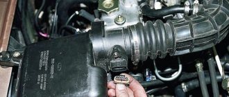
Hello, dear readers. We continue to study motorcycle-type carburetors. In the previous publication, we got acquainted with the main issues of the formation and ignition of a combustible mixture. Today we will study the main dosing system, consider its operating principle and adjustment methods.
Carburetor adjustment
Each of the carburetors is adjustable to several values. After performing this operation, change:
- filling the float chamber with gasoline;
- the value of the maximum idle speed;
- saturation of the fuel-air mixture entering the engine.
Adjusting the quality of the mixture is quite easy. Every car enthusiast can do this:
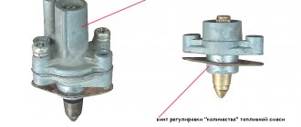
- On a warm engine, using the mixture quality adjustment screw, set the number of revolutions to no more than 900 on the tachometer;
- We reduce the quality of the mixture to the maximum possible by tightening the adjustment screw. We bring the engine to very low speed;
- Gradually unscrewing the screw, we bring the speed to normal so that the engine runs smoothly. You can’t overdo it here; it’s better to perform the operation again. Increased idle speed will increase fuel consumption, so additional adjustments are made.
There are situations when the speed has to be increased due to failures in the engine. For example, if the speed does not change when rotating the screw. There are several reasons for this failure
You need to pay attention to:
- solenoid valve jet - it may be clogged;
- channel located under the mixture quality adjustment screw. If gasoline is of poor quality, it becomes clogged;
- solenoid valve - it may be the one that is faulty.
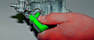
Checking the serviceability of the valve is quite simple. With the engine turned off, disconnect the wire from the electromagnet, unscrew the solenoid valve and disconnect the fuel nozzle. Now turn the key in the ignition switch and bring the wire removed from the valve.
A click and retraction of the valve stem into the body indicates the serviceability of the electromagnet. Otherwise, we change this device unit. Craftsmen advise an easier way. With the engine running, pull off the wire. If the engine stalls, you can continue working - the valve is working properly.
If debris gets into the nozzle, it should be cleaned. Cleaning is very simple. The jet can be purged using a pump or compressor. Often the specks are so small that they are not visible, but it is better to play it safe and, if the part is removed, then it is blown out to eliminate this problem. After completing all the operations, we put the nozzle in place and check the operation of the system.
It is not always possible to clean the idle air passage under the mixture adjustment screw on the road. Often it becomes so clogged that it cannot be vented, and disassembling the carburetor is necessary to eliminate the problem. Only after this does it become possible to clear this channel. In such a situation, there is a temporary solution.
Using a wrench, loosen the fastening of the solenoid valve on the carburetor until the engine is operating normally and drive home. In this case, gasoline passes by the idle fuel jet and this leads to increased fuel consumption. The main “symptom” of this malfunction is interruptions at minimum speeds and the engine turning off when the gas pedal is depressed, so mandatory cleaning of the channels and subsequent adjustment will help get rid of the breakdown.
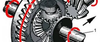
Operating principle of the main dosing system
The needle moves inside the calibrated part of the atomizer and at low throttle lifts the cross section through which fuel is sprayed is small. As a result, fuel consumption is also low, which is required to maintain the correct mixture composition at low elevations. At higher throttle lifts, the conical part of the needle with a smaller diameter appears in the fuel spray zone, thereby increasing the flow area of the nozzle. This allows you to increase the fuel supply, as is necessary for normal engine operation. This design and the corresponding operating principle of the main metering system makes it possible to maintain the desired mixture composition, so the engine is able to operate correctly at any throttle position.
Interaction of the needle with the sprayer
Now that the principle of operation has become clear, the principle of adjusting the main dosing system becomes clear. Adjustment is carried out using a needle and a calibrated nozzle hole.
What is the jet responsible for?
You should start by answering the question of why jets are needed in carburetor engines.
Here we are talking about a component of the carburetor system with a special calibration hole. This allows you to dose the supply of fuel or air. Therefore, depending on their purpose, jets can be divided into fuel and air.
As the cross-section on the main jet, which is the fuel element, increases, the mixture becomes richer. If you increase the cross section on the auxiliary (air) component, this will make the mixture lean.
All this allows us to say that the parts in question affect the fuel consumption of the car’s engine.
Purchase and replacement of jets
When purchasing a gas stove, do not forget to check the availability of suitable jet kits. If you miss this important point and direct the gas through unsuitable nozzles, you can get unstable operation. The burner will smoke, periodically go out, or will not be able to light up at all when ignited.
If for some reason the stove does not come with jets that match the type of gas, you can easily purchase them separately. Information about the diameter of the jets must be indicated in the instructions for the gas appliance.
Table of average jet parameters for most gas stove models:
| Burner type | Gas type (pressure) | |||
| NG G20 (20mBar) | LPG G30 (50 mBar) | NG G25 (20mBar) | LPG G30 (30 mBar) | |
| Small burner | 0.75 mm | 0.43 mm | 0.70 mm | 0.50 mm |
| Middle burner | 0.92 mm | 0.55 mm | 0.92 mm | 0.65 mm |
| Large burner | 1.15 mm | 0.60 mm | 1.15 mm | 0.75 mm |
| Oven burner | 1.20 mm | 0.65 mm | 1.15 mm | 0.75 mm |
| Grill burner | 0.95 mm | 0.60 mm | 0.95 mm | 0.65 mm |
Replacing (installing) the nozzle will not be difficult - you just need to unscrew the old one with a wrench and screw the new one in its place. Only in some cases may additional adjustment of the primary air supply and adjustment of the minimum stable flame level be required.
Superficial and quick cleaning
Obviously, clogged jets reduce their performance. Therefore, any owner of a car equipped with carburetor injection should have an aerosol spray on hand for cleaning. It is also called “carbicleaner”.
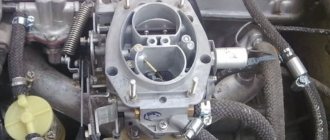
Sometimes, it is enough to remove the VF (filter) cover and spray the carb with spray so that engine operation returns to normal. However, this only applies to minor cases of blockage. And such a superficial method rarely helps to correct the situation as a whole, although it does produce results.
In addition to the aerosol can, be sure to have a tool for dismantling the VF. After all, having taken it out, you can clean it much better. For example, by additionally removing the solenoid valve (EMV). By unscrewing the element, you can gain access to the holes in various parts of the carb. Liquid is supplied through them from a can. In this manner, it will be possible to more deeply process the XX system and the first chamber of the carb.
Carbcleaner should also be sprayed into the second chamber. This must be done through the channels of the air jets. In general, correct injection of an aerosol composition implies an application in which the liquid hits the walls of the chambers and diffusers. The damper must be processed at the same time. For these purposes, a thin tube is included with the aerosol can, which makes it possible to clean hard-to-reach areas of the unit.
It is recommended to additionally apply liquid to the levers (for example, in the place where the damper drive lever is installed). This will remove traces of carbon deposits and dirt from the control parts, which will normalize the operation of the carburetor engine.
You should know that the cleaner does not take effect until 5 minutes have passed after application. This time is enough for the composition to soften the deposits and wash away the dirt. Only after this, after a pause, can you try to start the engine. It is recommended to start the engine not in the standard way, but using a choke. This will make it possible for the internal combustion engine to function without a solenoid valve (after all, it was removed). But just launching will not give a complete picture of normal operation. You still need to actively apply the throttle to correctly determine how the crankshaft rotates in all modes.
Some experienced motorists advise doing this as well. Increase the engine speed, then hold the accelerator pedal in this position and ask an assistant to spray additional aerosol into the chambers and valves.
It is recommended to repeat the cleaning procedure with an aerosol without removing the carburetor several times, especially if the deposits are old. Only at the final stage can you install the EMC and plug back, and at the end push the suction handle into place.
Attention. The EMC should only be tightened with the engine running. Assembly must be carried out carefully, first clamping the valve by hand. Then tighten it with a wrench, but no more than one-fourth of a turn. You need to be able to hear the moment when the engine just wants to stall. This will be a signal to stop tightening.
Types of jets and their ratio
Motorists are quite interested and sometimes need to find out where and what jet is installed on the carburetor of their vehicle from the factory.
Having studied the principle of operation, it is worth taking a look at the types of jets.
Parts differ depending on the functions performed. This is also affected by the location in the carburetor system. As a result, we can distinguish the following varieties:
- fuel;
- air;
- compensation;
- with idle speed.
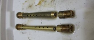
The element is assessed based on its operational properties. It is required to determine the volume of liquid that passes through the hole in a certain period of time. Such elements are marked. This is a 3-digit number. It is applied mainly to the end part.
Using the marked number you can find out about the performance of the jet. It is calculated in cubic centimeters at a pressure of 1000 millimeters of mercury. This is the volume of fuel passing through the hole.
The holes in the jet are strictly calibrated. If you use the wrong cleaning tools, the part can be completely damaged. And then only replacement will solve the problem.
Non-ferrous metals are used to make jets. This causes the parts to be susceptible to deformation. Therefore, you should be extremely careful when cleaning.
For each chamber, it is necessary to manufacture a corresponding jet, that is, fuel or air. The choice is made based on the cross-section of the carburetor diffuser. Usually, special sets of jets are produced for different cars and models, which differ in the diameter of the hole provided. This largely answers the question of what kind of jet should be in the carburetor in order for the engine to provide optimal performance.
This feature should be taken into account here. To increase dynamics and improve acceleration of the car, a large main (fuel) jet is often installed. This in parallel affects the increase in fuel consumption.
To determine the optimal ratio of two jets for your carburetor, it is recommended to look at the owner's manual and take into account the manufacturer's recommendations. The ratio can be from 80 to 100 to 125 to 165. Depending on this, the mixture can be lean, overly enriched, or optimal.
About the selection of jets according to a multi-colored plate found on the Internet
So, dear readers, I have reached this article. Stock up on popcorn and cola, right now I’m going to smash to smithereens another tale that has been circulating on the Internet for quite some time.
So. The following sign has been circulating on the Internet for a long time.
Some guy, excuse me, asshole, drew this sign in Photoshop, wrote some numbers from a flashlight there, and now all the young novice car enthusiasts of 20 years old consider this sign almost a standard, and stubbornly select jets based on it . Ignoring all attempts to reach them. And when you start telling them that this sign is COMPLETELY USELESS, they start poking it under their noses with the words “look, I found it on the Internet, what are you telling me here.” And it doesn’t matter that I make up to twenty to thirty carbs a month, that I have more work experience than they have in their browser search history for the keywords “big tits close-up, watch online without SMS and registration.” This tablet is considered by them to be the ultimate truth. By the way, there are several options. The same literate person drew, no less.
Who can tell me, QUANTITY is Collie's test word, right?
And then such car enthusiasts come, with the jets selected according to these plates, with the double spout of the accelerator pump wrapped in the first chamber, they come, which means they are standing at my place, crying - they say, help me, the car doesn’t drive at all, the consumption is high, I’m already tired of refueling - at a volume of 1200 in the city 13 (thirteen. Carl.) liters
Let's start with the fact that the stoichiometric ratio in AFR is not 14.9:1, but 14.7:1 for gasoline, 15.6:1 for propane. And the ratio of 14.9:1 is absolutely nothing. Perhaps this is the ratio that will provide the fuel obtained by the well-known Vasily Alibabaevich Ali Baba by mixing some donkey urine into it.
But the people who select the jets according to this sign happily gobble up such noodles, liberally removing them from their ears. “People eat – and that’s fine” – that would be more correct.
Go ahead. How the fuel-air jet combination works in a Solex carburetor. As practice has shown, not everyone has an understanding of how a carburetor works. Or rather, not only everyone can understand the principle of operation of the carb, few people can do it.
The figure below shows the structure of the emulsion chamber of a Solex carburetor.
The emulsion chamber has two main jets - a fuel jet, installed at the bottom of the emulsion well, and an air jet, installed on top. The air jet has an emulsion tube with holes. The diameter of the holes and their location are different, which determines the degree of leanness of the mixture at different speeds.
How it all works. When the engine is not running, or in XX mode, the level in the emulsion well is approximately the same as in the float chamber - the law of communicating vessels. As the speed increases, the amount of air sucked in through the main air jet increases, and its share in the gasoline-air mixture also increases. It begins to enter the emulsion channel through the very holes in the emulsion tube. What happens is that the higher the speed, and the larger the diameter of the air jet, the level in the emulsion channel can be considered LESS, if you take into account the amount of fuel entering through the main fuel jet. That is, in fact, the air jet VIRTUALLY lowers the fuel level in the emulsion channel by adding some air to the fuel, the amount of which depends on the diameter of the air jet, the diameter and location of the holes in the emulsion tube.
It’s very cool to see this when driving on the instruments. When I purchased the ShDK LC-1, I began to study the operation of the carburetor in different modes, including when driving. The picture is as follows. Idling - the mixture composition is set to 14.7:1 (in fact, I make it a little richer, somewhere around 14.4-14.5:1, this gives the engine a softer operation and the engine does not overheat so much). Triggering of the LV - 12 with kopecks to 1. Triggering of the transition (partial load mode, the XX jet operates simultaneously at XX and at the transition - 13.8: 1). But at 2500 rpm in 5th gear, 90 km/h on the highway, the mixture ratio on the 21081 carburetor with 95/165 jets in the first chamber is 15.8:1, and with 95/155 jets in the first chamber is 15.2:1, that is, a carburetor Solex makes the mixture lean at high speeds, which is its beauty.
Main types of jets and their selection
The industry produces 2 types of carburetor jets, which are included in each repair kit:
- fuel;
- air.
They are made for each camera of the device. The choice of jet depends on the cross-section of the large and small carburetor diffuser. Repair kits are produced differently - for each model and brand of car. The parts differ in hole diameter. How to adjust the correct operation of the engine - information necessary for every vehicle owner.
Quite often, the Solex carburetor is installed on cars of other brands, with the most powerful engines. In this case, the machine will work intermittently, because the VAZ jets will not be able to do their job efficiently - due to the diameter being insufficient to supply the enriched mixture.
Often, car enthusiasts install a large fuel part for better acceleration and dynamic driving. In this case, one should not forget about the increase in fuel consumption. Also, increasing the diameter of the nozzle by several orders of magnitude will not always give a good result. The table can tell you how to choose jets.
If the engine capacity is 1.6 liters, you should not install a main jet from a powerful engine on it. If you are no longer satisfied with the acceleration of your car, you may need to look for another reason, for example:
- low compression level in one of the cylinders;
- the adjustment of the ignition system has gone wrong;
- one or more spark plugs are faulty;
- Replacement of high-voltage wires is required.
These are just some of the reasons and malfunctions, by eliminating which you will get a fast car again. Car enthusiasts have different opinions about altering jets, but most believe that it is not worth doing. Sometimes, those who like to save money install jets whose sizes are smaller than the recommended ones. In this case, you get an economical, but very weak car that will take a very long time to accelerate. Ozone carburetor jets should not be installed in a Ford carburetor. They should be on the classic Zhiguli.
Adjusting the mixture composition
Adjustment with needle
In Dellorto carburetors, the needle is fixed in the throttle valve using a locking ring installed in one of the grooves (on the cylindrical part of the needle).
Conventionally, the grooves are numbered from the blunt end of the needle, that is, from the top. The higher the groove in which the locking ring is installed relative to the sprayer, the lower the needle is lowered. This means that in order for the conical part of the needle to exit the atomizer, the throttle must be raised higher. Conversely, if you need to engage the tapered part of the needle at lower throttle lifts, you need to raise the needle by moving the stopper to a lower groove (second, third...). For example, in practice, the consequence of a rich mixture may be slowness in gaining speed and a dull, deep exhaust sound. In this case, it is necessary to lower the needle by moving the locking ring to the grooves above.
However, very often it is impossible to tune the carburetor well by changing only the position of the needle. In addition to the position, it may be necessary to vary the geometric parameters of the needle (meaning the taper and length of the conical part). They significantly affect the carburetion process, and engine response directly depends on this. Thus, there is a need to replace it with another one with more suitable geometric parameters.
For each family of Dellorto carburetors there is a wide selection of metering needles with different geometries. As necessary, during the tuning process, you can select a more suitable needle and begin testing. For example, you may not get a rich enough mixture at a certain throttle lift with the needle raised as high as possible. In this case, you need to try a needle with the same taper, but in which the taper will begin earlier, i.e. the cylindrical part will be shorter. In certain cases, needles with different tapers can be used to better suit a particular type of engine. When conducting this type of experiment, it is always best to vary only one parameter at a time.
Adjustment using a spray gun
The atomizer has a calibrated hole at the end that communicates with the diffuser.
In Russian-language literature, the phrase “nozzle diameter” is often used, which means the diameter of this hole. As a rule, there is a certain set of nozzles of various diameters for a specific carburetor. As the diameter of the nozzle increases, the mixture becomes richer, and vice versa - it becomes leaner as it decreases. Of course, you can achieve the same effect by changing the diameter of the dosing needle. However, a needle of the appropriate diameter may be difficult to obtain. In this case, it is much easier to select a sprayer, if such a need arises at all, since Dellorto carburetors are initially optimized for the specific type of engine for which they are intended.
Thus, carburetor tuning is most often done by selecting jets, setting the needle height and selecting its shape, while the atomizer and throttle valve angle remain unchanged even with the appropriate replacement kits.
Types of jets and their functions
The part is distinguished by the functions it performs, as well as depending on its location in the carburetor. Can be divided into several types: air jet, compensation jet, fuel jet. There is also an idle jet. The part is evaluated based on its operating properties. The amount of liquid passed through a calibrated hole in a certain amount of time is calculated. The part is marked with a three-digit number if it is a carburetor jet
, which is usually applied to the end. This number allows you to determine the functionality of the jet in cubic centimeters if the water column pressure is 1000 mm.
Carburetor jets. Types and sizes of jets
The hole that is located in the nozzle must be strictly calibrated. It is not recommended to clean the part with sharp objects so as not to disrupt its functionality.
The jet is made of non-ferrous metal, so it is easy to deform.
The main function of the nozzle is strict dosing of fuel or air (depending on what kind of nozzle it is) for further spraying into the combustion chamber of the cylinder. In fact, this spare part directly affects the dynamic characteristics of the car. Specially selected and tuned jets can make the engine dynamic and powerful, or vice versa - more economical, but not so responsive.
How to solve the clog problem?
Sequence of actions for cleaning the jets:
- completely remove the air filter;
When cleaning the jets with a thin wire, be careful not to damage the hole; it is recommended to blow through rather than clean
.
using a screwdriver, loosen the clamps that secure the hoses intended for supplying fuel; then you need to unscrew the plug of the third filter in the carburetor, remove the filtration element, having previously cleaned it, and then blow it out using a conventional pump; remove the carburetor cover; blow out: the idle jet, also the air jet, all valves and channels of the special sprayer from the accelerator pump, the transition system jets; We clean the fifth mixture screw when idling, then we blow through all the fuel channels, as well as the carburetor systems. If necessary, you can completely replace the jets from the repair kit. After performing this operation, install the carburetor cover and tighten the screws.
Thus, as we see, the nozzle is a simple part of the car’s fuel system, but it also needs periodic checking, cleaning or replacement.
Connection and setup
Changing the jets yourself is not difficult, but if the equipment is under warranty, then such manipulations can void it. If possible, it is better to consult a specialist. A professional will correctly change the jets and will be responsible for the safety of the further operation of the gas stove.
Connection to bottled gas
Have you decided to buy a new gas stove, but the old one is still functional? The best option would be to take it to the dacha and connect it to the cylinder. To do this, you just need to replace the standard jets with nozzles for a stove for liquefied gas, and also connect the cylinder itself to the stove.
The process of connecting bottled gas to the stove is technically simple, but you need to carefully approach all manipulations:
- Screw the reducer onto the cylinder, while installing the gasket.
- Screw the fitting onto the inlet pipe of the stove. And here you will need a gasket.
- Connect the gas hose to the stove using a fitting.
- Secure the hose with clamps.
- If the gas cylinder is installed outside the room, on the street, then a piece of pipe must be installed in the hole in the wall so that the hose does not fray.
Requirements for the hose:
- the length must be at least 1.5 m;
- the hose must be secured and motionless;
- it should not bend or break;
- You must use only a special hose for gas equipment;
- Replace at the end of its service life;
- systematically check the hose for damage.
Once the connection is complete, check the stove for leaks. Open the gas and coat all joints with soapy water. If a leak is detected, tighten the nuts, harnesses, and replace the gaskets. When replacing a cylinder, such a check is also necessary.
Rich air-fuel mixture
The composition of the fuel mixture depends on the concentration of air and gasoline that enters the internal combustion engine cylinders. An intensive intake of air and, accordingly, saturation of liquid fuel with it occurs when the vehicle speed increases. As a result, the concentration and proportions of air and fuel in the air-fuel mixture change, resulting in the formation of a lean or rich mixture.
The fuel mixture is prepared in the carburetor. If the concentration of fuel in a mixture is higher than the concentration of air, then it is called rich or high-calorie. The combustion rate of such a mixture is very low, which is why a certain volume of it burns out in the muffler of the car.
A fuel mixture is considered normal if it consists of 14 kg of air and 1 kg of liquid fuel. If part of the air is exceeded, the fuel mixture is considered lean, and part of gasoline is considered rich.
A carburetor is an integral part of a car’s fuel system, each part of which is designed to perform specific functions. Proper operation of the entire structure ensures the normal functioning of the vehicle engine and traffic safety.
Main dosing system sprayer
The simplest atomizer is a tube connecting the main fuel jet to a diffuser. Engineers conventionally divide sprayer designs into “two-stroke” and “four-stroke”. Some nozzles (called the four-stroke type) have rows of holes around the perimeter, drilled all the way through into the main fuel well.
Sprayers differing in the design of emulsion tubes
Nozzle design for two-stroke engines
The nozzle is screwed into a nozzle (Generally speaking, a hydraulic nozzle is a short pipe for releasing liquid into the atmosphere or flowing liquid from one reservoir to another, also filled with liquid), fixed in the carburetor body.
Pairing the sprayer with the nozzle
As can be seen in the figure below, at the junction of the sprayer and the nozzle, an annular slot is formed, which turns into an annular cavity. The cavity is connected to the atmosphere through an additional air channel. This allows air to enter the diffuser through the annular slot. If the atomizer has holes for emulsifying fuel, air is also supplied to it through an auxiliary channel.
Annular gap between sprayer and nozzle
The inlet of this channel is usually located in front of the diffuser in its inlet part (under the letter b
in the figure below).
The hole next to it is the idle air duct. Sometimes, to reduce the influence of pressure pulsations in the intake receiver, the auxiliary channel communicates directly with the atmosphere. For example, as shown in the picture under letter a
, through the tube on the right side of the carburetor.
Methods for communicating the auxiliary air channel with the atmosphere
In total, the main dosing system works as follows. Under the influence of vacuum, the fuel rises through the nozzle. The flow of fuel is regulated by a jet and a metering needle. Part of the air passes through an additional channel and enters the annular cavity. As a result, intense mixing of fuel and air occurs in the area above the annular slot and the nozzle.
Operation of the main dosing system with a push-pull type atomizer: Fuel from the float chamber rises along the atomizer 6, passing through the nozzle 7, which, together with the needle 3, regulates the fuel consumption. The fuel is initially mixed with air passed through channel 2 in the annular gap between nozzle 5 and the atomizer. The emulsion enters the diffuser 4 and is mixed with air entering through the inlet device 1.
Along with the diameter of the atomizer, the adjusting parameter is the diameter of the air channel (the larger it is, the poorer the mixture), as well as the height of the protrusion of the atomizer and the nozzle into the diffuser. Options for sprayers and nozzles are presented in the figures below.
Sprayers varying in height
Various nozzle options
Let's take a closer look at the atomizer.
Under constant other conditions, the less the atomizer protrudes into the diffuser, the lower the height the fuel needs to rise from the float chamber, which contributes to an earlier start of the process of fuel atomization in the diffuser. The "low" spray is a characteristic feature of sports carburetors. On the contrary, with a high atomizer, the fuel mixture will be leaner in transient (unsteady) conditions.
The same physical principles apply to the operation of an air nozzle. Its protrusion into the diffuser creates resistance to the air flow, so a zone of strong vacuum is created behind the protrusion, which contributes to the flow of fuel. In other words, the higher the nozzle, the greater the vacuum behind it and the richer the mixture becomes. You can lean the mixture using a carburetor with a low nozzle height.
How to choose jets for a carburetor
It is recommended to clean the jets every 30 thousand km, and replace them only in 3 cases:
- clogged internal channels of the nozzle that cannot be cleaned;
- physical damage;
- tuning (for example, to increase engine power, reduce fuel consumption).
The main thing you need to pay attention to when selecting jets is the diameter of the diffuser. For this there is the following formula:. Fuel nozzle (FJ) = Diffuser size × 4
Fuel nozzle (FJ) = Diffuser size × 4
When increasing the diffuser by 1 mm, the diameter of the fluid fluid must be increased by 10%.
The VJ is selected depending on the diameter of the TJ. There is also a formula for this:
Air jet (AJ) = Fuel jet size + 50
Also, without resorting to various calculations, you can buy a special repair kit for your carburetor model, which contains the necessary set of jets. But many experienced experts point out that the quality of the jets in repair kits is lower than in those sold separately.
If tuning is performed, then it is worth remembering that this is an individual procedure for each individual carburetor. Often, the selection of jets is made experimentally, by searching and comparing the results.
The choice of jets depends on the purpose of tuning. To increase power and dynamics, you need to proportionally increase the diameter of the fuel and air jets. To reduce consumption, only TJs with a smaller diameter are installed. To change the diameter of the jets, you can use special drills (1 mm, 1.5 mm, 1.75 mm, 2 mm).
| Dimensions of standard jets on the most popular VAZ carburetors | ||||
| Carburetor name, (article) | Main fuel jet, 1 cam. / 2 cam. | Main air jet, 1 cam. / 2 cam. | Idle fuel jet, 1 cam. / 2 cam. | Idle air jet, 1 cam. / 2 cam. |
| DAAZ “Solex”, (21083-1107010) | 95 / 97,5 | 155 / 125 | 40 / — | 170 / — |
| DAAZ “Solex”, (21073-1107010) | 107,5 / 117,5 | 150 / 135 | 40 / — | 140 / — |
| DAAZ “Solex”, (21053-1107010-20) | 107.5 / 110 | 140 / 165 | 40+-3 / — | 140 / — |
| DAAZ “Ozone”, (2107-1107010) | 112 / 150 | 150 / 150 | 50 / 60 | 170 / 70 |
| DAAZ “Weber”, (2101–1107010) | 135 / 135 | 170 / 190 | 45 / 60 | 180 / 70 |
Using the Solex carburetor (21083-1107010) as an example, we will consider which jets to install to reduce consumption and which to increase power.
To reduce consumption in the first chamber, you need to install a fuel nozzle with a reduced diameter. Instead of 95, 92.5 is set. An idle speed fluid with a smaller diameter is also installed - instead of 40, 38 is installed.
To increase power, main fuel jets with an increased diameter are installed in both chambers of the carburetor. In chamber No. 1, instead of 95, 102.5 is set, in chamber No. 2, instead of 97.5, 110 is set.
Related terms
- Throttle valve
- Carburetor
- Diffuser
Relative values of fuel jets for Solex carburetors
| Ratio | Diffuser diameters | |||||||||
| Economical | 14 | 95,0 | 102,0 | 107,0 | 115,0 | |||||
| Economical power | 13,5 | 98,5 | 105,8 | 111,0 | 119,3 | |||||
| Power moderate | 13 | 102,3 | 109,8 | 115,2 | 123,8 | |||||
| Power normal | 12,5 | 106,4 | 114,2 | 119,8 | 128,8 | |||||
| Powerful dynamic | 12 | 110,8 | 119 | 124,8 | 134,2 | |||||
| Sport | 11,5 | 115,7 | 124,2 | 130,3 | 140 | |||||
| Factory values | 14 | 95,0 | 102,0 | 107,0 | 115,0 | |||||
| Air quantity in diffuser | 1330 | 1428 | 1498 | 1610,0 | ||||||
Replacing the jet
The selection of carburetor jets is carried out according to the markings. The number of each part in the set must correspond to the diameter, according to the table. When choosing a set of carburetor parts, decide what power and take-off speed will suit you. If you are setting nominal dimensions, then everything is simple - you must first select a kit. This is the most important job when purchasing. It should be remembered that 80% of the parts on the market are from China
Pay attention to this when choosing them. Then you can make repairs
To carry it out we will need to remove the carburetor from the engine. This will make further work more convenient
The carburetor removal diagram is described in other articles on the site; the only thing you need to pay attention to is the gasket between the carburetor and the engine housing
After removing the carburetor with a screwdriver, unscrew the screws securing the cover. We remove it and use a flat screwdriver to unscrew the fuel and air jets. On air ones, it is necessary to disconnect the emulsion tubes. Then new parts are installed or old serviceable jets are cleaned. For greater confidence, it is necessary to calibrate the jets on a special stand. “Incorrect” parts should be removed, but this operation cannot be performed independently.
Before installation, all carburetor parts must be washed in cleaning liquid, dirt and carbon deposits removed, and all channels cleaned. We are starting to install new jets. In this case, the correct location of each part of the mechanism must be observed. The jets on the carburetor must be placed according to the markings.
After assembling the device, install it on a new gasket and tighten the fastening nuts. Primary adjustment and tuning is carried out using the mixture saturation and idle speed adjustment screw. These operations will allow you to start the engine. We connect all the hoses and wires, install a new air filter. We make sure that all parts are in place and securely fastened. We test run the engine. Now we need to adjust the operation of the motor and warm it up.
After looking at the engine temperature data, we adjust its operation.
Having completed all the operations of installing jets and adjusting the carburetor reliably and in compliance with all instructions, think about how much fuel you will save.
Typical faults
There are several main reasons why the behavior of a car with a carburetor engine changes for the worse. This is due to the following phenomena:
- The element is clogged. As a result, the throughput has changed. Requires cleaning and in some cases replacement.
- A component with a smaller size was installed. This entails an increase in efficiency, but also a simultaneous decrease in power. The car accelerates with difficulty and is difficult to overtake.
- A larger part is used than recommended by the manufacturer. The engine output increases, the dynamics improve, but the engine's appetite seriously increases.
To solve problems, you can use one of the methods. Namely:
- replacement;
- adjustment;
- cleaning
Let's start with the adjustment procedure.
Self-adjustment
If you have a high-quality and clean jet, you don’t always need to change it. Sometimes the problem is solved by adjusting the quality of the mixture.
This is done using the following algorithm:
- the engine warms up to its normal operating temperature;
- using the adjusting screw, the speed is set to no more than 900 units per minute, guided by the tachometer;
- the quality of the mixture is reduced to a minimum by tightening the corresponding screw;
- revolutions are reduced to low values;
- the screw is gradually unscrewed;
- Average speeds are set for smooth operation of the internal combustion engine.
This completes the adjustment. If something doesn’t work out the first time, repeat the procedure using the same instructions.
Replacement
A new replacement jet is selected based on the marking of the part. The part number in the kit must correspond to the diameter according to the manufacturer’s table.
When choosing a kit, you need to focus on what dynamics and fuel consumption will suit you.
The easiest way to navigate is by the nominal factory values. Here you will only need to open the instruction manual.
Replacement is a rather painstaking procedure, but not very complicated. It is important to follow this sequence:
- first, the carburetor is removed from the engine, since it is much more convenient to work this way;
- the gasket located between the engine body and the carburetor itself is removed;
- depending on the condition, the gasket may need to be replaced;
- the cover fixing screw is unscrewed;
- the cover is removed using a flat screwdriver;
- both jets (fuel and air) are dismantled;
- the emulsion tube is disconnected from the air element;
- before reinstallation, all parts are washed with a special liquid;
- new components are installed according to markings;
- changing gaskets;
- the fastening nut is tightened.
After replacement, it is necessary to perform initial adjustment and adjustment using the mixture saturation screw and the idle speed adjustment screw.
Now connect all the hoses and try to start the engine. Additionally, it is recommended to replace the air filter.
What are jets and what are they eaten with?
The jet is an important part of the burner. This element is a bolt-shaped injector and is necessary to ensure that the fuel comes out at a given pressure. To do this, the nozzle has a hole of a given diameter, which determines the parameters of the gas stream.
The gas jet should be related to the power of the stove itself. Power is determined by many parameters - how completely the gas coming out burns, whether the burner smokes, etc.
The jets are threaded and the top has six edges. The diameter of the hole in the nozzle for a stove with bottled gas is smaller than in the case of natural gas (with the other characteristics of the burners being the same).
If you install jets designed for natural gas on a stove with a cylinder, the gas pressure will be greater and the air consumption will be less. Because of this, the flame will be long and orange, and the stove will begin to smoke. Only replacing the jets with ones suitable for a specific type of fuel will solve the problem.
What are nozzles (jet) for in a gas stove?
Since the combustion process of different types of gas has its own characteristics, the connection of the gas stove to the propane cylinder and gas pipeline must be carried out with correctly selected nozzles.
If the stove is configured for liquefied gas from a cylinder, then the holes in the nozzles should have a smaller diameter than similar ones for natural gas. This is explained by the pressure difference:
- The gas in the cylinders is under high pressure.
- The gas pressure in the main pipe is lower than in the cylinders.
Considering the difference in diameters, it should also be noted that regardless of the type of gas used, the small and large burner of the stove will respectively have a smaller and larger diameter of the nozzle holes.
If the jets are installed incorrectly
Determining that the wrong jets are installed on the stove is quite simple.
This will be noticeable by the following signs:
- the burner ignites with a bang, goes out, burns with a hum and is unstable;
- the flame is low and hisses, extinguished;
- The color of the fire turns yellow and soot is formed.
All this indicates incomplete combustion of gas, which means there is a high risk of an emergency. Therefore, you need to replace the injectors with those provided by the manufacturer.
You can do this yourself, taking all precautions, or invite a specialist. But no matter how easy this work may seem, in the absence of basic knowledge about the structure of the stove, you should not take it on
Replacing jets
Let's discuss how to change the nozzles on a gas stove yourself. The designs of the slabs are different; let’s look at the most typical ones. In new models, access to the nozzles is easier (you just need to remove the burner).
In other cases, it is necessary to carry out a number of operations:
- Remove the grate from the stove and dismantle the burners.
- Remove (raise) the top panel by unscrewing the fastening screws. Some plates use special latches instead of screws.
- Unscrew the screws securing the burner to the stove.
- Release the gas supply pipe. To do this, you need to remove the clamp in the form of a curved plate. It is usually located on the faucet side. Place the handset to the side.
- Unfasten the second end of the tube by removing the retaining plate using a screwdriver or pliers.
- Carefully unscrew the old nozzle. Lubricate the threads with graphite lubricant. After replacing the old seal, install a new jet.
Assembly is carried out in reverse order.
How to replace jets in an oven
Algorithm for replacing jets in this part of the plate:
- Open the technical drawer and swing it open to the extreme position of the oven door.
- The nozzle is usually located behind the left wall of the oven in a housing into which a curved arc-shaped burner is inserted. Pull the floor out through the special slot - it should come out freely. Set it aside.
- Remove the screws holding the burner in place and remove it from the stove. On the left you will notice a hole through which gas enters the burner. That's where the nozzle is located.
- The jet may have become stuck to the burner - do not try to remove it. If you damage the thread, you will have to replace not only the nozzle, but also the burner body.
- Unscrew the screws that secure the left side wall of the stove and set it aside. There will be a nut at the end of the pipeline. By unscrewing it, you will remove the housing.
- Having removed the housing, you can begin replacing the jet. You may need a special liquid if it is stuck.
Assembly is carried out in reverse order.
After replacing the jets, connect the stove to the central gas pipeline or cylinder using a flexible connection. In the first case, the end of the hose is connected to the gas pipe via a fitting. The winding is wound onto the thread clockwise, and a sealing ring is placed in the hose nut.
The connections are tightened tightly with a gas wrench (an improved version of the adjustable wrench). The second end is connected to the outlet thread of household appliances using various seals.
Replacing jets for bottled gas
When you need to switch the stove to gas from a cylinder, it is necessary to install new jets specifically designed for this. The requirement is dictated by the difference in gas pressure from the line and the cylinder, which directly affects the size of the flame and the formation of soot. In other words, using a cylinder on a stove with nozzles under a gas pipeline is extremely dangerous.
As noted above, jets are already supplied by default with most modern stoves. If they are not included in the kit, you will have to buy more. The prices are quite affordable.
Required Tools
Replacing jets should be entrusted to gas service specialists who have the necessary knowledge and qualifications and will be able to correctly adjust the gas supply when switching to another fuel. It is not recommended to remodel a gas stove yourself.
If the user decides to change the nozzles with his own hands, he will need the following tools:
- crosshead screwdriver;
- set of open-end and ring wrenches.
How to change nozzles on a gas stove
First, the stove is disconnected from the gas, if it was connected. After this, they proceed according to the following algorithm:
- Remove the top cover of the gas stove by unscrewing the screws to get to the burner.
- Then they find the latch, squeeze its ends and carefully remove it. After this, the tips with nozzles are removed from the traverse with burners.
- The tip is released from the socket and removed from the gas pipeline tube. The o-ring is removed from it and placed on the tube.
- Use a socket wrench to unscrew the jets counterclockwise. New ones are installed in their place.
- Carry out reverse installation. The accuracy of reassembly determines how smoothly the burner will burn.
It is easier to change modern models of gas stoves to use a different fuel. To gain access to the burner, only the grates with burners are removed. Then remove the tips and install new nozzles.
Replacing the jets in the oven is carried out as follows:
- open the oven door and the lower compartment of the device;
- pull out the floor of the oven compartment;
- unscrew the burner fastenings;
- carefully, so as not to break the thread, unscrew the nozzle (it is located on the left in a special housing);
- install a new nozzle and reassemble.
If the jet has become stuck during operation, unscrew the three fastening screws and remove the left side wall. Using a 17 wrench, unscrew the nut and move the pipeline to the side. Then unscrew the two screws that secure the nozzle body to the wall. The stuck thread is treated with WD-40 or kerosene and the nozzle is unscrewed. A new one is installed in its place and the oven is installed in the reverse order.
After replacing the nozzles, the stove is connected to a cylinder or central gas supply using a flexible connection. If the equipment is connected to a gas main, one end of the hose is connected to the gas pipe through a plumbing fitting or fitting. The thread of the drive is pre-winded clockwise. An O-ring is inserted into the hose nut. The parts are connected and tightened using a gas wrench. The other end of the flexible liner is connected to the thread of the plate outlet, using flax or fum tape for fastening.
If the device needs to be connected to a cylinder, one end of the flexible hose is connected to the stove nozzle through a fitting and secured with a worm clamp. The other end is attached to the gearbox and also tightened with a clamp. The reducer is connected to the cylinder using paronite gaskets; it must be positioned horizontally. The fasteners are tightened using an open-end wrench.
Then check the tightness of the connection. All connections are coated with a soapy solution and gas is released. If the soap does not foam, then there are no leaks. After this, the gas is lit in the burners one by one. A blue flame without yellow or red tints indicates that the job was done correctly.
Symptoms of incorrect selection of gas injectors
Incorrect operation of the gas stove burners can be judged by the following signs:
- A balanced burner ignites without popping, does not go out, burns evenly and without buzzing.
- With an optimal ratio in the mixture of gas and air, the fire acquires a blue color with a greenish tint.
- With too much air, the flame becomes low and burns with a hiss. In this situation, it is also possible for the flame to come off the burner and go out.
- A milky-yellow fire with soot indicates insufficient oxygen supply and incomplete combustion of gas.
The information discussed about jets for gas stoves is advisory in nature.
It is very important to understand that the use of gas for domestic purposes does not forgive neglect. At the slightest suspicion of unstable operation, do not engage in amateur activities and immediately consult with specialists