Hello everyone, I’m sitting here drinking beer, reading the feed and once again I see “I assembled it according to the diagram, it doesn’t work, help.”
I will try to explain how it works, why it is needed and how to connect it.
1. Here is the most common 4-pin relay
2. It has a diagram of the legs on the lid.
Pins 85 and 86 are the coil. Contact 30 - common contact Contact 87 - normally open contact At the bottom, the legs themselves have the same markings.
3. How to connect it correctly
From the decoding of the contacts it is clear that while the control signal (+) is not applied to the relay, then contact 30 and 87 are open.
4. Operating principle
At rest, i.e. when there is no power to the coil, contact 30 is open. When power is simultaneously supplied to contacts 85 and 86 (one contact is “plus” and the other is “minus”, no matter where it is, if there is no diode marking on the relay), the coil is “excited”, that is, it is triggered. Then pin 30 is connected to pin 87.
5.Why is it needed?
Relay is an electrical device (switch) designed to close and open various sections of electrical circuits for given changes in electrical or non-electrical input quantities. Types of relays may differ in the control signal and in design, we will not dwell on this. Moreover, all this is on the same Wikipedia. We only note that the most common: The relay is designed for switching large load currents. In other words, it is a switch, or even simpler - the principle of operation of a relay - with a small current (for example, a button signal) to turn on circuits with a large current. And a relay is used when the actuator (starter, generator, fan, heated mirrors, horn, etc.) consumes more current (up to 30-40 amperes).
Watch the video
Connecting a signal through a relay immediately solves many problems, the main one of which is electrolysis of wires due to unfavorable operating conditions of the vehicle (dirt, moisture).
Information business website
The general meaning of connecting via a relay is the load on the switch that controls the installed equipment. At rest, i.e.
Separately, I would like to dwell on an important point, it concerns the use of DRLs in conjunction with high beam headlights. Without supplying voltage to the winding contacts, it is permanently closed to contact 87a.
The contact parameters and the maximum switching current are also indicated under the electrical diagram. But I don’t want to strain the wiring through the relay.
Usually a relay has 5 contacts, there are 4-pin and 7-pin, etc. Legislation Before practicing installing DRLs, I would like to dwell a little on the legal standards for installing DRLs, as well as the rules of their operation. Coil actuation voltage.
5 pin relay diagram
How to connect an audio signal
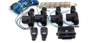
Having collected all the necessary elements, only now can you move on to the most important action - connection.
- The first step is how to connect a signal through a relay: remove the “-” terminal from the battery.
- Next, you need to remove the sound signal and install a relay in its place.
- Wire connection options
- A so-called “leech” is installed on the “+” wire that connected the sound signal. A wire approximately 15 cm long with male-female terminals is connected to it;
- If it is not possible to install a “leech”, you can strip the positive wire, then solder a piece of wire with a “mother” terminal to it. The soldering area must be sealed with insulating tape or pre-applied heat shrink.
- Next, the “+” wire must be connected to the relay. To do this, a wire with a newly formed process is connected to the 86th and 30th contacts.
- Let's move on, figuring out how to connect a signal to a VAZ or any other car. Now you need to connect the remaining negative wire to the relay. To do this, you need to use pin 85.
- An audio signal is connected to the remaining 87th contact of the relay.
- Last step: put the “-” on the battery.
VAZ 2107 - injector diagram (fuel injection control system)
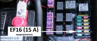
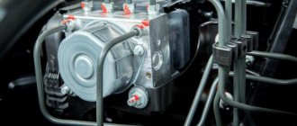
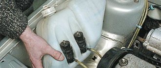
Most of the relays, as well as the voltage regulator, are located in the engine compartment.
Location of the VAZ 2106 relay in the engine compartment
If it fails, it is recommended to replace the relay assembly, since if the winding is burned out, or the relay contacts are severely burnt, it is difficult to properly restore its functionality.
Air signal connection
If you need to connect not an electric, but an airborne sound signal, the connection procedure will be almost the same as described above. The difference is that the wire from the relay does not go to the sound signal itself, but to the compressor (the engine that supplies air to the signal). And the pneumatic signal pipes are connected to the compressor through tubes.
When you press the horn, air from the compressor is supplied to the horns. With the help of a membrane installed in them, a sound signal is obtained.
You can read about how to connect the headlights yourself in our article How to connect the headlights.
In my opinion, everything is already clear, and they have already written about this many times, but it may be useful to someone. For example, I recently gave a car I had made to a man, and over time his signal stopped working. You can’t travel all over Moscow for trifles, so he asked me to draw a diagram for him, I did it, but don’t disappear. I decided to post it publicly.
Description, I will try to use simple understandable language:
Two opposite contacts on the relay, numbered No. 86 and 85, are the so-called control contacts. If voltage is applied to them, the relay will close, and then direct voltage will flow through contacts No. 30-No. 87. Well, let’s say a contact that you need to break and briefly close, let’s say a signal. Why through a relay? Well, let’s take the interior button for example, the contacts on the buttons are weak and are not designed for direct load, and if you apply the plus from the battery through the button, say, to the starter, then after the first use the button will melt. Therefore, through the interior button we connect the control wires to the relay, and the direct plus to the consumer, in our case the signal. Thus, through a relay from the battery to the input (contact No. 87) and output (contact No. 30) to the consumer (Signal).
Standard automotive relays. Schemes and some applications
Annex 1. A brief overview of domestic standard relays in housings as shown in the photograph below.Below you will find information from one manufacturer; there are other manufacturers and foreign analogues. For this part of the article, the main thing is to make it clear to the average car enthusiast that relays can be interchangeable, have different circuits, different numbers of contacts, depending on their purpose.
Domestic relays of this series mark the normally closed contact as 88. In imported relays this contact is everywhere called 87a
Differences and variety of relay numbers mean different mountings, housing design, degree of protection, coil control voltage, switched currents and other parameters. Sometimes when choosing an analogue it is necessary to take into account some parameters.
Typical relay circuits. Tsokolevka.
According to scheme 1, the following 5-contact (switching) relays are produced:
With 12V control – 90.3747, 75.3777, 75.3777-01, 75.3777-02, 75.3777-40, 75.3777-41, 75.3777-42
With 24V control – 901.3747, 901.3747-11, 905.3747, 751.3777, 751.3777-01, 751.3777-02, 751.3777-40, 751.3777-41, 751.3777-42
According to scheme 1a with an anti-interference resistor:
With 12V control – 902.3747, 906.3747, 752.101, 752.3777, 752.3777-01, 752.3777-02, 752.3777-40, 752.3777-41, 752.3777-42
With 24Volt control – 903.3747, 903.3747-01, 907.3747, 753.3777, 753.3777-01, 753.3777-02, 753.3777-40, 753.3777-41, 753.3777-42
| Scheme 2 | Scheme 2a |
According to scheme 2, the following 4-contact (closing/closing) relays are produced: With 12V control – 90.3747-10, , 75.3777-10, 75.3777-11, 75.3777-12, 75.3777-50, 75.3777-51, 75.3777-52, 75 4.3777 , 754.3777-01, 754.3777-02, 754.3777-10, 754.3777-11, 754.3777-12, 754.3777-20, 754.3777-21, 754.3777-22, 754.3777-30, 754. 3777-31, 754.3777-32
With 24Volt control – 904.3747-10, 90.3747-11, 901.3747-11, 905.3747-10, 751.3777-10, 751.3777-11, 751.3777-12, 751.3777-50, 751.3777-51 , 751.3777-52, 755.3777, 755.3777-01, 755.3777-02, 755.3777-10, 755.3777-11, 755.3777-12, 755.3777-20, 755.3777-21, 755.3777-22, 755.3777-30, 755.3777-31, 755.37 77-32
According to scheme 2a with an interference resistor: With 12V control – 902.3747-10, 906.3747-10 With 24V control – 902.3747-11, 903.3747-11, 907.3747-10
| Scheme 3 | Scheme 3a |
According to scheme 3, the following 4-contact (breaking/switching) relays are produced: With 12V control – 90-3747-20, 904-3747-20, 90-3747-21, 75.3777-20, 75.3777-202, 75.3777-21, 75.3777-22, 75.3777-60, 75.3777-602, 75.3777-61, 75.3777-62
With 24Volt control - 901-3747-21, 905-3747-20, 751.3777-20, 751.3777-202, 751.3777-21, 751.3777-22, 751.3777-60, 751.3777-602, 751.3777 -61, 751.3777-62
According to scheme 3a with an anti-interference resistor: With 12V control – 902-3747-20, 906-3747-20, 902-3747-21, 752.3777-20, 752.3777-21, 752.3777-22, 751.3777-60, 751.3777- 61, 751.3777 -62,
With 24Volt control – 903-3747-21, 907-3747-20, 753.3777-20, 753.3777-21, 753.3777-22, 753.3777-60, 753.3777-61, 753.3777-62,
ATTENTION!!! Relays of the 19.3777 series have a housing similar to the one above. The circuit of these relays has protective and decoupling diodes. Such relays have a polarized winding. These relays are not mentioned here in the article because they have limited use.
Relays of modern cars.
Differences and variety of relay numbers mean different mountings, housing design, degree of protection, coil control voltage, switched currents and other parameters. Sometimes when choosing an analogue it is necessary to take into account some parameters.
| Scheme 4 | Scheme 4a |
According to scheme 4, the following 5-contact (switching) relays are produced: With 12Volt control - 98.3747, 982.3747 With 24Volt control - 981.3747, 983.3747
According to scheme 4a with an anti-interference resistor: With 12Volt control - 98.3747-01, 98.3747-011, 982.3747-01 With 24Volt control - 981.3747-01, 983.3747-01
| Scheme 5 | Scheme 5a |
According to scheme 5, the following 4-contact (closing/closing) relays are produced: With 12Volt control - 98.3747-10, 982.3747-10 With 24Volt control - 981.3747-10, 983.3747-10
According to scheme 5a with an anti-interference resistor: With 12Volt control - 98.3747-11, 98.3747-111, 982.3747-11 With 24Volt control - 981.3747-11, 983.3747-11
| Scheme 6 | Scheme 6a |
According to scheme 6, the following 4-contact (breaking/disabling) relays are produced: With 12Volt control - 98.3747-20, 982.3747-20 With 24Volt control - 981.3747-20, 983.3747-20
According to scheme 6a with an anti-interference resistor: With 12Volt control - 98.3747-21, 982.3747-21 With 24Volt control - 981.3747-21, 983.3747-21
Appendix 2.
Photos of the relays that I had to work with will be posted here. These are ordinary relays from a set of alarms and other additional equipment.
Checking work
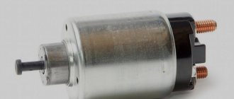
Sometimes, despite more than obvious signs of breakage or wear of the retractor, in reality everything turns out to be wrong. The car may behave similarly with some other malfunctions.
Therefore, in order to figure out whether the relay works or not, and also who is the real culprit for the violation of the functionality of the system, we will conduct several checks.
- Check the starter. Turn the ignition key. The starter should begin to turn, and the relay should make a characteristic click. If the starter is not doing its job, replace it. Relyukha has nothing to do with it in this case.
- Check the solenoid relay. To do this, there are two copper bolts on the back cover. Two contacts are attached to them. If the starter starts turning, then your relay has definitely failed and needs to be replaced. In this case, you should not remove the starter, which will allow you to get more accurate test results.
- If you have removed the starter, the check is performed slightly differently : Connect the contact wire of the retractor relay to the positive terminal of the battery;
- The second contact connects the starter ground and the battery charger;
- When the contacts are placed on the relay terminals, the relay should turn on with a characteristic click;
- If the operation is too slow, uncharacteristic, check the condition of the contacts. They often burn out or oxidize.
Signs of a malfunctioning retractor relay
A faulty traction relay can be identified by the following symptoms:
- when the ignition is turned on, there is no characteristic click accompanying the movement of the device’s armature to the rearmost position (the starter does not turn, the engine does not start);
- a click is heard, but the trigger does not fire;
- The relay is triggered, the starter starts the engine, but does not turn off.
If you turn on the ignition and find that the engine does not start, and one of the listed signs of a faulty starting device is present, try to find the problem yourself. In some cases, the damage may be on the surface, and it will only take a few minutes to fix it.
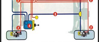
Starter wiring diagram
To understand the electrical part of the starter, let's first get acquainted with its circuit, try to figure out how it works, what elements it consists of, what task the individual elements of the circuit perform.
useful: Replacing the VAZ 2114 starter (step-by-step instructions)
The driver inserts the key into the ignition switch (6), and turning the key starts the process. Electric current from the battery (2) is supplied to the generator (3) and to the electromagnetic relay installed on the starter (1). A running generator begins to generate electricity and supplies it to the tires of the mounting block (4), from where current is supplied to the starting auxiliary relay and ignition switch. The relay completes the circuit and supplies current to the solenoid relay coil, which in turn causes the starter to turn the bendix. And start the engine.