- home
- Media center
- Articles
- Fuse on Gazelle
Menu
- News
- Articles
- Video materials
- Photo materials
- Publication in the media
- 3D tour
08.10.2019
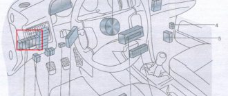
Depending on the year in which the GAZ-2705 and GAZ-3302 cars were produced, the Gazelle electrical circuit is protected by common fusible links, which are designed for different current ratings. And additional fuse blocks are located on a bracket, which in turn is installed on a shelf under the hood.
Fuses Gazelle 3302 2705
Gazelle fuses have their own color depending on the current strength. And if in the old-style car the green color corresponded to 16 Amperes, and the black color corresponded to 8 Amperes, then in the new-style cars the fuses have a wider range of colors:
- Red color corresponds to 10 Amps.
- Orange - 5 Amps.
- White - 25 Ampere;
- Blue - 15 Amperes;
- Yellow - 20 Amps.
This color division will help when replacing a blown fuse: you won’t need to look through each one, but just take the fuse of the desired color.
Lighting and light signaling
Headlights
Setting up headlights for gazelle 3302
The headlights include:
- side light lamps;
- direction indicator lamps;
- low beam lamps;
- high beam lamps;
- adjustment devices (for initial installation of headlights);
- electronic-mechanical corrector (to adjust the angle of the low and high beam depending on the vehicle load). The side lights and headlights are switched on using the central headlight switch. Switching the headlights (high-low) and turning on the turn indicators is carried out using the steering column switch.
The initial inclination of the light border of the low beam headlights is set using knobs 3 and 5 (Fig. 9.28) at the car manufacturer and is indicated on the upper bracket of the headlight.
Figure 9.28:
Headlight:
- diffuser;
- turn signal lamp socket;
- horizontal adjustment knob;
- low beam lamp cover;
- socket for adjustment in the vertical plane;
- wire connector;
- high beam lamp cover;
- headlight housing;
- H1 - high beam lamp;
- H7 - low beam lamp;
- PY21W – direction indicator lamp;
- W5W - side light lamp
To adjust the headlights depending on the vehicle load, electronic-mechanical correctors are installed in the headlights, allowing the driver to change the angle of the low and high beam beam. The tilt of the light beam is changed using the handwheel of a special electronic unit on the instrument panel.
The angle of the headlight beam is adjusted by changing the position of the headlight reflectors using electric motors with gearboxes and a tracking system installed in the headlight housings. When the control unit's handwheel is turned, power is supplied to the electric motors, which through gearboxes turn the headlight reflectors to a certain angle.
The angle of rotation of the reflectors is determined and controlled by sensors of the tracking system depending on the position of the control unit.
Manual adjustment of the headlights must be done using the screen (Fig. 9.29) in the following order:
- check the tire pressure and, if necessary, adjust it to normal;
- install an unloaded car with a driver at a distance of 10 m from the screen;
- turn the control knob of the electronic corrector to position “0”;
- turn on low beam;
- adjust the light beams using knob 3 (see Fig. 9.28) and a Phillips screwdriver through socket 5 for each headlight in turn.
For adjusted headlights, the horizontal section of the cut-off line should align with the X-X line (Fig. 9.29), inclined sections
The cut-off line should correspond to Fig. 9.29A (with “AL” marking on the diffuser) and fig. 8.1.35B (marked on the diffuser “OSVAR”), and the points of intersection of the horizontal and the beginning of the inclined sections of the cut-off line - with lines G–G and D–D. During operation, it is necessary to monitor the serviceability of the lamps. Lamps with darkened bulbs must be replaced.
Figure 9.29:
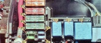
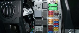
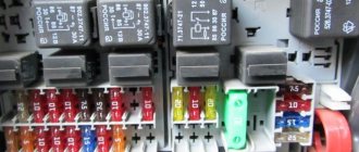
Fuse box of the new model Gas 3302 (Gazelle 3302) and Gas 2705 (Gazelle 2705).
GAZ cars, starting from 2003, have their own fuse block, the number of which has increased from 10 to 13. So, the top block from left to right includes fuses:
- engine control systems with a current of 25 A;
- alarm - 15 A;
- radio equipment, “Mass” switch - 15 A;
- electric motors for glass cleaner and washer - 10 A;
- ABC systems, low beam lighting relay - 10 A;
- brake lights - 10 A;
- sound signals and cigarette lighter - 20 A;
- clock, instrument cluster, sound relay - 20 A;
- electric pump of the heating system, electric motor of the additional heater - 15 A;
- speed sensor, instrument cluster, window wiper relay, reverse light lamp - 10 A;
- oxygen concentration sensor - 5 A;
- engine control systems - 15 A;
- direction indicators - 10 A.
The lower block includes, from left to right, the following fuses:
- reserve with a rated current of 25 A;
- main beam headlight on the right, control lamp for turning on the main beam - 15 A;
- high beam headlights on the left - 15 A;
- low beam headlights on the right - 10 A;
- low beam headlights on the left - 10 A;
- rear fog lamps and turning them on - 10 A;
- reserve - 20 A;
- reserve - 20 A;
- lampshades: cabin, cargo compartment, car step lighting, passenger bus compartment, engine compartment lamp - 15 A;
- cigarette lighter, switches, instrument cluster lighting - 10 A;
- reserve - 5 A;
- side light on the right, headlight range control, lighting of the box with things - 15 A;
- parking light on the left, signal lamp for turning on the fire, license plate lamps - 10 A.
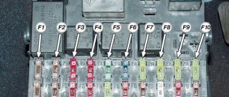
To get to the fuses, press the cover latch to the left and open it. We remove the fuse by pressing the terminal at the top or bottom.
Various circuits depending on the engine
The ZMZ 402 carburetor engines were the very first to be installed on the Gazelle. For the operation of the internal combustion engine ignition system, it was necessary to supply power to the ignition coil, distributor and switch. The next engine to enter the series was the ZMZ 406, also in a carburetor version.
But it no longer had a coil, distributor and switch; instead, an electronic ignition control unit was installed.
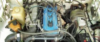
Later, Gazelles began to be equipped with a ZMZ 405 injection engine, which instead of a carburetor had a distributed injection system.
This is what the ZMZ 405 engine looks like
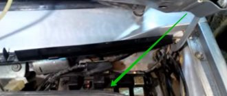
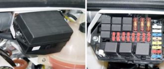
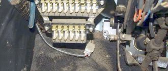
Fuse box in the engine compartment Gas 3302 (Gazelle 3302) and Gas 2705 (Gazelle 2705).
The fuse box, located in the engine compartment, in cars of different years has 2 fuse links and 4 types with an ABS system:
- GAZ 2705 and 3302 of the old model have fuses of 30 A (protection of the lighting circuit) and 60 A (protection of all other circuits except lighting and starter);
- GAZ 2705 and 3302 of the new model - 60 A (circuit protection, excluding starter, lighting and generator) and 90 A (lighting and generator circuit protection);
- Models with an anti-lock braking system have fuse links of 40 A (lighting circuit), 90 A (alternator circuit), and two 60 A (the first powers the ABS, the second powers everything except the starter, generator, ABS, lighting).
The starter does not have fuses, since the circuit is designed for short-term current.
This construction - dividing the block into upper and lower rows - is designed to provide protection against short circuits or voltage surges in a GAZ car. The manufacturer supplies each car with an additional set of fuses with tweezers included. This is necessary so that if one of the fuse links fails, it can be easily removed using it. But before this procedure, you must disconnect the battery.
How to determine the malfunction?
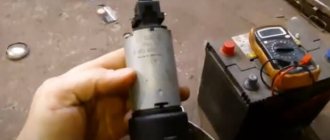
If malfunctions occur in the operation of the equipment, first of all you need to check the integrity of the safety devices. If a short circuit or voltage surge occurs in a wiring circuit, the safety elements are the first to fail, protecting the major devices and electrical equipment connected to a particular circuit. Since a visual check is not always effective, troubleshooting should be done using a tester - a multimeter.
The diagnostic procedure consists of removing the fuses from their seats and further checking the sockets. If you have identified a failed fuse, this does not mean that the test can be completed, since a short circuit can occur simultaneously in several circuits (video author - Denis Legostaev).
If a short circuit occurs in the wiring of a car with a carburetor or injection engine, then you need to diagnose the condition of the circuits. Of course, if all the fuses were intact. Before diagnosing, you should disconnect the mass; directly for checking you will need a tester or test light. When using a lamp, one of its contacts should be connected to the base and the other to the center contact.
The check itself goes like this:
- First, the ignition key should be set to position I;
- then the probes of the tester or lamp must be connected to the contacts in the fuse sockets in turn;
- if the lamp does not light up, this indicates that there are no short circuits in the section of the circuit being tested, but if it lights up, then a short circuit has been detected.
Another important point is diagnosing the integrity of electrical circuits. In this case, the search principle is quite simple - for diagnostics you will need the same tester (a voltmeter or ohmmeter will do) or a lamp with wires. You will need to connect one of the probe contacts to the vehicle body, and use the second contact to measure the power at the connecting points between yourself and the equipment.
It is best to start in the middle of the circuit and check easily accessible areas first. In addition, to diagnose a break, it should be understood that most often circuit damage occurs in places where the wiring is bent. Moreover, as practice shows, wire harnesses are very rarely damaged.
Another breakdown in the electrical circuit is poor contact at the connections; searching for such a fault is best done using a tester - a voltmeter.
There are two diagnostic methods:
- One probe of the tester should be connected to the car body, and the second to the connection terminal; voltage measurement is carried out in both directions. Please note that the voltage drop should be no more than 0.5 volts.
- The next method is to connect one wire to the contact on one end of the plug, and the second to the contact on the other side of this plug. If the tester shows more than 0.5 volts, this indicates that the contacts on the plug should be cleaned (the author of the video is the MZS TV channel).
The difference between the headlight switch relay on the Volga
Fuses gazelle business
The circuit uses universal electromagnetic relays separately for low and high beams, except for the Gas 3110 car, in the circuit of which a specially designed relay is used that switches the headlights. An electromagnetic relay consists of one or two fixed contacts, a movable contact attached to the armature of an electromagnetic coil and an electromagnet. When voltage is applied to the terminals of the coil, an electromagnetic field is created in it, magnetizing the core to which the armature is attracted, closing the contacts.
The Gas 3110 headlight switch relay, like a universal relay, has an electromagnet, but not only a moving contact is attached to its armature, but also a switching device lever. When switching the headlights, power is briefly supplied to the relay, the armature of the electromagnetic relay is attracted, closing the additional high beam contacts and activating the switching mechanism. After releasing the headlight switch lever, the circuit on the relay electromagnet coil breaks; the armature moves away, opening the additional contacts, and the switching device closes the contacts of the low or high beam headlights.
The difference between the headlight switch relay on the Volga
The circuit uses universal electromagnetic relays separately for low and high beams, except for the Gas 3110 car, in the circuit of which a specially designed relay is used that switches the headlights. An electromagnetic relay consists of one or two fixed contacts, a movable contact attached to the armature of an electromagnetic coil and an electromagnet. When voltage is applied to the terminals of the coil, an electromagnetic field is created in it, magnetizing the core to which the armature is attracted, closing the contacts.
The Gas 3110 headlight switch relay, like a universal relay, has an electromagnet, but not only a moving contact is attached to its armature, but also a switching device lever. When switching the headlights, power is briefly supplied to the relay, the armature of the electromagnetic relay is attracted, closing the additional high beam contacts and activating the switching mechanism. After releasing the headlight switch lever, the circuit on the relay electromagnet coil breaks; the armature moves away, opening the additional contacts, and the switching device closes the contacts of the low or high beam headlights.