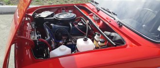
The history of AvtoVAZ began with the production of the VAZ-2101 car, or popularly known as “Kopeyka”. This was the first of the family of cars to receive the designation “Classic”.
The Kopeyka used a contact ignition system, which is currently significantly outdated. But it had one positive point - installing the VAZ-2101 ignition was quite simple and did not require special equipment. And although the “Classic” has not been produced for a long time, there are still many cars with VAZ 2101-2106 markings traveling on the roads. Therefore, next we will consider how to adjust the ignition on a VAZ-2101. On other models of this family, this operation is performed similarly.
Article on the topic - Design of the ignition system of VAZ 2101 cars
Correction of the angle in the closed state of the contacts.
So, if our car has a transistor or classic ignition system, we can start setting it up.
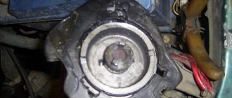
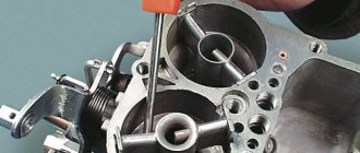
- First of all, remove the distributor cover and clean the distributor contacts with a file to ensure a tighter fit between them (important for a classic ignition system).
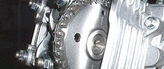
- After which we need to set the maximum distance between the contacts, a special crankshaft wrench will help us with this; we turn the crankshaft with it until there is the greatest distance between them. If there is no key, you need to enable
4th gear and push the car to the desired position.
- Unscrew the screw that secures the contact group to the plate.
- Using a 0.4mm probe, we adjust the contact group so that it fits flush with the contacts. Then tighten the screw and fix the position of the contacts.
- Now we check the position of the contacts using two probes 0.35mm and 0.45mm. If we did everything correctly, the smaller diameter probe should pass freely while the larger probe should not pass at all.
This operation helped us set the required gap of the distributor contacts. Critical condition when contacts are closed. New distributors have a precise angle. Many people advise checking the angle after adjustment; it should be in the range of 52o-58o degrees. If we succeeded, we proceed to the next stage.
Installation of ignition on a VAZ 2101 by spark
To correctly install the installed breaker, you must first check the functionality of the spark plugs. If they have a strong coating and carbon deposits on them, it is pointless to install and adjust the torque. You can learn more about the reasons for the formation of soot and how to remove plaque in this article. As you know, adjustment is one of the main nuances in car maintenance.
Stages
To adjust the BSZ contactless or contact ignition, you will need a strobe light - thanks to it you can get the most accurate result. If you do not have a strobe, then adjustment is carried out by spark. So, how to install SZ?
Installation is carried out as follows:
- First of all, before turning on the ignition on the VAZ 2101, the vehicle must be warmed up to operating temperature. Start the engine and wait about 10 minutes, after which the power unit can be turned off.
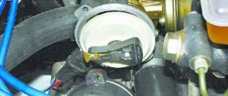
- The next stage of installation will be to loosen the distributor. After the knot is loosened, the central cable should be removed from it.
- To adjust the ignition of a VAZ, the first cylinder of the engine must be placed at top dead center.
- Next, you need to turn on the car’s ignition, while holding the cable from the coil in your left hand. With your right hand, in turn, you should slightly twist the distributor clockwise. The rotation should be about 10-15 degrees, but no more. At the same time, hold the cable above the metal.
- Then, the distributor must be turned very slowly counterclockwise. This procedure is carried out until you notice a spark jumping between the cable and the metal. When the spark jumps, we can assume that the device is configured. At this point, the installation can be considered complete. If the spark still does not appear, the distributor may need to be repaired, but only diagnostics can make an accurate diagnosis. Sometimes the problem lies in the operation of the ignition coil. All further actions, including connecting the VAZ distributor and connecting wires, are carried out in the reverse order.
Electronic ignition design
To install a contactless system on a “classic” VAZ 2107 with a carburetor, it is advisable to study how it works. This will help you correctly assemble the circuit and successfully put it into operation. BSZ for old carburetor Zhiguli models consists of the following elements:
- distributor, also known as the distributor of the ignition system;
- high-voltage coil of a new design (different from the old one, which works with mechanical contacts);
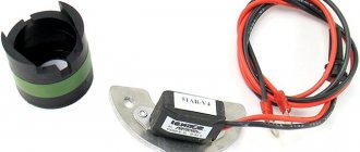
- switch responsible for system management;
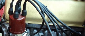
- high-voltage and ordinary wires with connectors and terminals connecting the listed elements;
- spark plug.
Reference. Since the new ignition system does not have a contact group, and its operation is controlled by an electronic unit, the names “contactless” and “electronic” are equally suitable for it.
Elements of the electronic ignition system of the VAZ 2107
The new high-voltage coil has 2 windings. The primary one is made of a large cross-section conductor and is connected to the vehicle's electrical network through the ignition switch relay. The secondary winding is wound with a large number of turns of thin wire and connected by a high-voltage wire to a distributor consisting of the following parts:
- a housing with a centrally mounted shaft;
- a movable contact (the so-called slider) is fixed at the end of the shaft;
- A cover is placed on top of the body, where high-voltage large-section wires leading to the spark plugs are connected;
- there is a protrusion (cam) on the shaft, opposite which there is a Hall sensor;
- a vacuum diaphragm is attached to the side, providing ignition advance.
The switch is connected by small cross-section conductors to the distributor and coil; its task is to control the timely supply of sparks to the spark plugs.
Reference. In newer modifications of the VAZ 2107, where there is an injector instead of a carburetor, there is no separate switch. There is no need for it, since the on-board computer controller is in charge of spark generation and fuel supply.
Connection diagram of contactless system elements
Adjustment methods
In general, system adjustment is carried out in three stages. The first includes adjusting the angle of the closed state of the contacts. Keep in mind that it depends directly on the size of the gap in the contacts of the distributor. The second stage includes setting the angle at which the ignition advance occurs, and the third stage allows you to check and correct the results obtained
It is necessary to pay special attention to the fact that all results must be clarified directly during the ride.
Adjustment will be needed if you use a classic or transistor ignition system in your car. In order to get started, you will first need to remove the cover covering the ignition distributor of the VAZ 2106. If your VAZ 2106 has a classic system installed, then before you begin the adjustment process, clean all the supplied contacts and check the care with which they fit to each other.
If you notice any deviations, carefully put the system in order by bending the necessary places in the contacts. Next, turn the crankshaft so that the maximum permissible distance is formed between the contacts of the VAZ 2106 distributor. Then unscrew the screw that secures the group; it is located on the bearing plate. And insert the probe, the thickness of which is 0.5 mm. Move the contacts so that it can move with little force.
To rotate the crankshaft, use a special wrench. If you don't have one, start moving the car slowly with fourth gear engaged. Of course, this will require some effort, because using a starter to carry out such work becomes almost impossible. This is due to the fact that it will be quite problematic to find the optimal rotation angle.
Proceed to directly measure the angle. Remove the high voltage wire from the distributor cover and connect it to the car. Next, using the ignition coil and the 12V bulb attached to it, attach to the wire that runs directly from the distributor to the coil.
If the installation was completed correctly, when you turn on the ignition, the light will start to light, and as soon as you open the contacts, it will go out. Then start rotating the engine crankshaft so that it moves clockwise. This work must be carried out until the light goes out. Remember the position in which the slider is located and mark it somewhere for yourself.
Distributor malfunctions, their symptoms and causes
Taking into account the fact that the designs of contact and non-contact type distributors are almost the same, their malfunctions are also identical. The most common breakdowns of the breaker-distributor include:
- failure of the cover contacts;
- burning or wear of the runner;
- changing the distance between the breaker contacts (only for contact distributors);
- failure of the Hall sensor (only for contactless devices);
- capacitor failure;
- Damage or wear of the movable plate bearing.
Let's look at the malfunctions in more detail in the context of their symptoms and causes.
Failure of cover contacts
Considering that the cover contacts are made of relatively soft materials, wear is inevitable. In addition, they often burn out, because a current of several tens of thousands of volts passes through them.
The more wear on the contacts, the greater the likelihood of them burning.
Signs of wear or burning of the cover contacts are:
- “triple” of the power plant;
- complicated engine starting;
- reduction in power characteristics;
- unstable idle.
Burnt or worn contact of the slider
The situation is similar with the slider. And although its dispensing contact is made of metal, it too wears out over time. Wear leads to an increase in the gap between the contacts of the slider and the cover, which, in turn, provokes the formation of an electric spark. As a result, we observe the same symptoms of engine malfunction.
The runner is also subject to wear and tear over time.
Changing the gap between contacts
The intercontact gap in the VAZ 2101 distributor breaker should be 0.35–0.45 mm. If it goes out of this range, malfunctions occur in the ignition system, which affects the operation of the power unit: the engine does not develop the required power, the car jerks, and fuel consumption increases. Problems with gap in the breaker occur quite often. Owners of cars with a contact ignition system have to adjust the contacts at least once a month. The main reason for such problems is the constant mechanical stress to which the breaker is exposed.
When changing the set gap, the sparking process is disrupted
Hall sensor failure
If problems arise with the electromagnetic sensor, the engine also begins to experience interruptions: it starts with difficulty, periodically stalls, the car jerks during acceleration, and the speed fluctuates. If the sensor breaks down altogether, you are unlikely to be able to start the engine. It rarely fails. The main sign of its “death” is the lack of voltage on the central high voltage wire coming out of the ignition coil.
If the sensor fails, the engine will not start
Capacitor failure
As for the capacitor, it also rarely fails. But when this happens, the breaker contacts begin to burn. You already know how it ends.
If the capacitor is broken, the breaker contacts burn out
Bearing failure
The bearing serves to ensure uniform rotation of the movable plate around the shaft. If it malfunctions (biting, jamming, backlash), the ignition timing regulators will not work. This can cause detonation, increased fuel consumption, and overheating of the power plant. It is possible to determine whether the moving plate bearing is working properly only after disassembling the distributor.
If a bearing malfunctions, interruptions in regulation of the SOP occur
INSTALLING THE IGNITION TIMING ON A VAZ 2101-VAZ 2107
Ignition timing - it plays a very important role in a car, it is thanks to it that the mixture ignites, we will explain to you in more detail if you do not understand what we are talking about, you already know that a car has pistons in its engine, and so thanks to them it works, but in order for them to go up and the engine to work, a mixture of air and gasoline is needed, this mixture then enters the car engine during its operation, and so after it gets into operation, the ignition is turned on, that is, it ignites this mixture when the pistons are at the very top and This is how the engine works, but what will happen if the ignition is installed a little earlier while the pistons are still at the lower mark, do you know? It can be assumed that the mixture will also ignite, but the engine will already work much harder, the piston cannot turn back, and when it strives upward, it will be stopped, as it were, by this earlier ignition and thus the engine will work worse, so after that when the mixture will ignite, you need to monitor and, if necessary, adjust the ignition angle so that it is as even as possible.
To set the ignition timing, you just need to take: Wrenches, as well as a special light bulb (it’s called a control) that runs on 12 volts or instead (If you have one) use a voltmeter, also don’t forget to stock up on a strobe light, thanks to it you will check whether you have adjusted the ignition timing correctly or not!
When should ignition timing be set?
If you notice that your car has started to work incorrectly, namely, the car has lost power, the speed has started to fluctuate (Especially at idle, this is noticeable), the engine has started to stall, and also to overheat strongly, although this never happened before, or to detonate (If you If you don’t know what detonation is, then study “This article”, everything is described in it), then most likely your ignition has gone wrong, it can go wrong because of your fault (This is when you climbed into the engine and did something with the distributor, removed for example), due to a faulty bearing in the distributor, the ignition timing may be off (For information on how to repair the distributor, read the article: “Repairing the distributor on a VAZ”), but install it first and if this is not enough for a long time, then you can think about repairing the distributor or replacing it with a new one (For information on how to replace the distributor, read the article: “Replacing the ignition distributor on classic cars”).
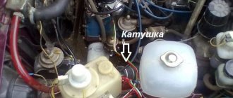
Let's learn about the distributor on the VAZ 2106
How correctly the ignition system is configured in your car has a strong impact on the overall performance of the car. Therefore, it is necessary to know exactly what actions will have to be taken if the VAZ 2106 distributor suddenly fails.
Distributor 30.3706 VAZ 2106.1 - ignition distributor shaft; 2 — wire for supplying current to the ignition distributor; 3 — latch for fastening the distributor cover; 4 — vacuum regulator housing; 5 - diaphragm; 6 — vacuum regulator cover; 7 — vacuum regulator rod; 8 — pipe for the vacuum hose from the carburetor; 9 — lubricating wick (filt) of the cam; 10 — support plate of the ignition timing regulator; 11 — ignition distributor rotor; 12 — side electrode with a terminal for the wire to the spark plug; 13 — ignition distributor cover; 14 — central terminal for the wire from the ignition coil; 15 — central carbon electrode with a spring; 16 — central contact of the rotor; 17 - resistor for suppressing radio interference; 18 — external contact of the rotor; 19 — driving plate of the centrifugal regulator; 20 — weight of the centrifugal ignition timing regulator; 21 — lever axis; 22 — breaker cam; 23 — breaker lever; 24 — stand with breaker contacts; 25 — breaker contacts; 26 — movable breaker plate; 27 - capacitor; 28 — ignition distributor housing; 29 — roller oil deflector clutch; 30 — bearing lock plate; 31 — bearing of the movable plate of the breaker; 32 — oiler body; 33 — screws for fastening the rack with breaker contacts; 34 — terminal clamp screw; a — groove for distinguishing ignition distributors 30.3706; b - groove for moving the stand with contacts
Contactless distributor
The VAZ 2101 non-contact type ignition distributor is practically no different from the contact type, except that a Hall sensor is used instead of a mechanical breaker. This mechanism is modern and more reliable, since there is no need to constantly adjust the distance between the contacts. Structurally, the sensor is located on the distributor shaft and is made in the form of a permanent magnet with a screen and slots in it. When the shaft rotates, the screen holes pass through the magnet groove, which leads to changes in its field. Using the sensor, the distributor shaft revolutions are read, after which the information is sent to a switch that converts the signal into current.
A non-contact distributor is considered a more modern and reliable device
Diagnostics
A non-contact ignition distributor is checked in the same way as a contact one, with the exception of the contacts themselves
Instead, attention is paid to the Hall sensor. If problems arise with it, the engine begins to work unstably, which manifests itself in the form of floating idle speed, problematic starting, and also twitching during acceleration.
If the sensor fails completely, the engine will not be able to start. At the same time, problems with this element arise infrequently. A clear sign of a Hall sensor failure is the absence of a spark at the central contact of the ignition coil, so not a single spark plug will work.
The Hall sensor does not fail very often, and if this happens, the fault can be identified by the absence of a spark
You can check the part by replacing it with a known good one or by connecting a voltmeter to the output of the element. If it turns out to be working, the multimeter will show 0.4–11 V.
You can check the Hall sensor with a multimeter by connecting the device to the output of the device
Many years ago, I installed a contactless distributor on my car, after which I practically forgot what a distributor was and problems with ignition, since there was no longer a need to periodically clean the contacts from burning and adjust the gap. It is necessary to adjust the ignition only if any repair work is carried out on the engine, which happens quite rarely. As for the Hall sensor, during the entire operation of the contactless device (about 10 years) it has never changed.
Ignition performance monitoring
The results of the ignition adjustment must be tested while the car is moving. Before this, pre-warm the engine and after accelerating 45-50 km/h, engage 4th gear and vigorously press the gas pedal. If the ignition is adjusted correctly, at this moment characteristic popping noises as a result of detonation should appear briefly (1-2 seconds) and immediately disappear, followed by a vigorous increase in speed. If this does not happen, turn the distributor body 1 position counterclockwise. When detonation continues for more than 2 seconds, the housing must be turned clockwise by 1 division.
Setting the timing using a light bulb
The need to adjust the ignition switch circuit, in particular, the timing of the advance, arises among owners of “kopecks” quite often. Adjusting the ignition distributor is necessary in case of increased fuel consumption, decreased power of the power unit, as well as in case of detonation and ring knocking. So that the set parameter no longer bothers you, the unit must be repaired, that is, configured correctly. Please note that before making a connection and adjusting the ignition distributor, you need to make sure that the spark plugs are working, and if necessary, dismantle them and clean them, as we reported above.
Before you begin, you need to find the marks on the chain pulley and crankshaft, these marks should be cleaned. The room where you are working should have good lighting, otherwise use a flashlight. If you have doubts about whether you can do everything correctly, it is better to contact a service station.
Stages
- First of all, you are required to rotate the crankshaft so that the mark on it is aligned with the mark located on the chain drive housing. If our “penny” has a power unit with a cylinder diameter of 79 mm, the crankshaft mark should be aligned with the middle mark of the chain drive. If the cylinder diameter is 76 mm, then the mark on the crankshaft should be combined with the outermost mark on the cover. This mark allows you to install the crankshaft in the MT.
- When all the marks on the shafts are aligned, you need to disconnect the cable that goes from the coil to the breaker-distributor device. The wire is disconnected from the terminal itself on the distributor, then you will need to connect the cable from the test lamp to it, which we will use for adjustment.
- The second lamp cable will need to be connected to the positive terminal of the battery.
- Using a 13mm wrench, loosen the screw that secures the breaker-distributor device.
- Then turn the body of this assembly slightly counterclockwise. Once you've done this, start slowly turning it in the other direction. As you can see, in general the adjustment principle is quite similar to that described above.
- The mechanism body rotates until the light goes out. Having achieved this, the assembly fixing nut should be tightened. All you have to do is install the cable from the distributor in place.
In principle, connecting the lamp and setting up the unit is not a problem. The ignition system of the VAZ 2101 is designed in such a way that in any case it will need periodic adjustments, this need especially often arises for drivers at the onset of a new season. If you are faced with a problem with the lock itself, then the VAZ 2101 ignition switch connection diagram will help you replace the device and connect it.
When installing a new VAZ ignition switch, it is necessary to correctly pinout the wires. After adjustment, check the quality of the work performed - if the engine knocks a little when accelerating to 50 km/h and switching to fourth gear, this indicates that the procedure was performed correctly.
Each car owner chooses which adjustment method he likes best!
Repair of contact distributor
It is better to repair the distributor-distributor or diagnose it after first removing the device from the engine. Firstly, it will be much more convenient, and secondly, you will have the opportunity to assess the general condition of the distributor.
Dismantling the VAZ 2101 breaker-distributor
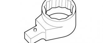
To remove the distributor from the engine, you will need two wrenches: 7 and 13 mm. The order of dismantling work is as follows:
- Disconnect the negative terminal from the battery.
- We find a distributor. It is located on the left side of the power plant cylinder block.
- Using your hand, carefully remove the high-voltage wires from the contacts of the cover.
- Disconnect the rubber tube from the vacuum regulator reservoir.
- Using a 7 mm wrench, unscrew the nut that secures the low-voltage wire terminal.
- Using a 13 mm wrench, loosen the nut holding the breaker-distributor.
- We remove the distributor from its mounting hole along with the sealing ring that acts as an oil seal.
- We wipe the lower part of the shaft with a clean rag, removing traces of oil from it.
Disassembly of the distributor, troubleshooting and replacement of failed components
At this stage we will need the following tools and materials:
- hammer;
- thin punch or awl;
- 7mm wrench;
- slotted screwdriver;
- fine sandpaper;
- multimeter;
- medical syringe for 20 cc (optional);
- anti-rust liquid (WD-40 or equivalent);
- pencil and sheet of paper (to make a list of parts that will need to be replaced).
The procedure for disassembling and repairing the distributor is as follows:
Disconnect the device cover from the body. To do this, you need to bend the two metal latches by hand or using a screwdriver. We inspect the cover outside and inside. There should be no cracks or chips on it.
We pay special attention to the condition of the electrodes. If minor traces of burning are found, remove them with sandpaper.
If the contacts are severely burnt, or the cover has mechanical damage, we add it to the list of replacement parts.
We evaluate the condition of the runner. If it shows signs of wear, we add it to the list as well. Otherwise, clean the slider with sandpaper. Turn on the multimeter and switch it to ohmmeter mode (up to 20 kOhm). We measure the resistance value of the slider resistor. If it goes beyond 4–6 kOhm, we add the resistor to the list of future purchases.
Using a screwdriver, unscrew the two screws securing the slider. Let's take it off.
We inspect the weights of the centrifugal regulator mechanism. We check the condition of the springs by moving the weights in different directions. Under no circumstances should the springs be stretched or dangling. If they are hanging out, we make a corresponding entry in our list.
Using a hammer and a thin drift (you can use an awl), we knock out the pin that secures the shaft coupling. We remove the coupling.
We inspect the splines of the distributor shaft. If signs of wear or mechanical damage are detected, the shaft definitely needs to be replaced, so we “take a pencil” to that too. Using a 7 mm wrench, loosen the nut securing the condenser wire. Disconnect the wire. Unscrew the screw that secures the capacitor. Let's take it off.
We carry out diagnostics of the vacuum regulator UOZ. To do this, disconnect the second end of the hose that comes from the “vacuum manifold” from the carburetor fitting. We again put one of the ends of the hose on the fitting of the vacuum regulator reservoir. We place the other end on the tip of the syringe and, by pulling out its piston, we create a vacuum in the hose and reservoir. If you don’t have a syringe at hand, you can create a vacuum with your mouth, after first clearing the end of the hose of dirt. When creating a vacuum, the movable plate of the distributor must rotate. If this does not happen, most likely the membrane in the reservoir has failed. In this case, we add the tank to our list.
Remove the thrust lock washer from the axle. Disconnect the rod.
Unscrew the tank mounting screws (2 pcs.) with a flat screwdriver.
Disconnect the tank.
Unscrew the nuts (2 pcs.) securing the breaker contacts. To do this, we use a 7 mm wrench and a screwdriver, which we use to hold the screws on the back side. We dismantle the contacts. We inspect them and assess their condition. If they are badly burnt, we add the contacts to the list.
Using a slotted screwdriver, unscrew the screws that secure the plate. Let's take it off.
We remove the movable plate assembly with the bearing from the housing.
We check the bearing for play and jamming by shaking and turning the inner ring. If these defects are identified, we prepare it for replacement. We purchase parts according to our list. We assemble the distributor in the reverse order, replacing the failed elements with new ones. There is no need to install the cover and slider yet, since we will still have to set the gap between the contacts.