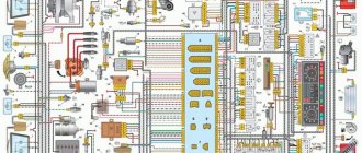
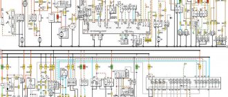
Electrical diagram of VAZ-2121
1 – side direction indicators; 2 – front lights; 3 – VAZ-2121 headlights; 4 – electric motors for headlight cleaners; 5 – sound signals; 6 – relay for turning on the headlight cleaners and washer; 7 – relay for turning on low beam headlights; 8 – relay for turning on the high beam headlights; 9 – windshield washer electric motor; 10 – sensor of insufficient brake fluid level; 11 – plug socket of a portable lamp; 12 – oil pressure warning lamp sensor; 13 – oil pressure indicator sensor; 14 – coolant temperature indicator sensor; 15 – ignition distributor; 16 – spark plugs; 17 – windshield wiper motor; 18 – ignition coil; 19 – generator; 20 – carburetor shut-off valve; 21 – VAZ-2121 starter; 22 – headlight washer motor; 23 – voltage regulator; 24 – battery charge warning lamp relay; 25 – battery; 26 – windshield wiper relay; 27 – additional fuse block; 28 – main fuse block; 29 – parking brake warning lamp switch; 30 – switch for differential lock warning lamp; 31 – reverse light switch; 32 – switch for the carburetor air damper warning lamp; 33 – brake light switch; 34 – heater electric motor; 35 – relay-interrupter for direction indicators and hazard warning lights; 36 – additional resistor of the heater electric motor; 37 – instrument lighting switch; 38 – headlight switch; 39 – direction indicator switch; 40 – sound signal switch; 41 – wiper switch; 42 – windshield washer switch; 43 – ignition switch; 44 – external lighting switch; 45 – heater switch; 46 – switch for headlight cleaners and washer; 47 – cigarette lighter; 41 – alarm switch; 49 – lamp switches located in the door pillars; 50 – oil pressure gauge with insufficient pressure warning lamp; 51 – fuel level indicator with fuel reserve warning lamp; 52 – tachometer; 53 – parking brake warning lamp; 54 – battery charge indicator lamp; 55 – control lamp for the carburetor air damper; 56 – speedometer; 57 – indicator lamp for external lighting; 58 – turn signal indicator lamp; 59 – control lamp for high beam headlights; 60 – relay-interrupter for the parking brake warning lamp; 61 – brake fluid level warning lamp; 62 – differential lock warning lamp; 63 – coolant temperature indicator; 64 – lampshades; 65 – sensor for level indicator and fuel reserve; 66 – rear lights; 67 – license plate lights.
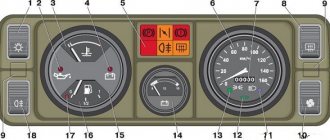
Dashboard
All control devices are interconnected. This combination consists in particular of:
- speedometer;
- tachometer;
- coolant temperature indicator;
- 12 indicator lamps;
- battery charge sensor;
- fuel level indicator.
All of them are located on the panel.
The schematic diagram shows the combinations available on the instrument panel:
- tachometer (1);
- stabilizer (2);
- panel illumination (3);
- coolant heating indicator (4);
- gasoline level (5);
- toxicity reduction systems (6);
- heated luggage door glass (7);
- fog lights (8);
- high beam (9);
- outdoor lighting (10);
- turn signals (11);
- TG level (13);
- oil pressure (14);
- differential locks (15);
- fuel reserve (16);
- seat belts (17);
- parking brake (18).
D1, D2 are diodes (type IN4002).
Cars manufactured before 1996 also have a voltmeter (12 in the diagram).
Finally, there are two resistors:
- R1 – at 470 Ohm (0.25 W);
- R2 –51 Ohm, (5 W).
Diagram of the VAZ-21213 car
Electrical diagram of VAZ-21213 (Carburetor). Years of manufacture: 1993-2009. The diagram shows a relay for rear fog lights, used since 2000; before that they were turned on directly from a latching switch.
1 – front lights; 2 – side direction indicators; 3 – windshield washer electric motor; 4 – headlight washer electric motor*; 5 – switch; 6 – battery; 7 – starter; 8 – generator; 9 – VAZ-21213 headlights; 10 – gearmotors for headlight cleaners*; 11 – sound signal; 12 – spark plugs; 13 – carburetor limit switch; 14 – carburetor solenoid valve; 15 – ignition coil; 16 – windshield wiper gearmotor; 17 – carburetor solenoid valve control unit; 18 – ignition distributor sensor; 19 – coolant temperature indicator sensor; 20 – oil pressure warning lamp sensor; 21 – plug socket for a portable lamp**; 22 – brake fluid level warning lamp sensor; 23 – windshield wiper relay; 24 – relay for turning on the rear fog light***; 25 – relay for turning on the heated rear window; 26 – relay for turning on headlight cleaners and washer*; 27 – relay for turning on low beam headlights; 28 – relay for turning on the high beam headlights; 29 – ignition relay VAZ-21213; 30 – starter activation relay; 31 – relay-breaker for alarm and direction indicators; 32 – heater electric motor; 33 – additional resistor of the heater electric motor; 34 – backlight lamps for heater control levers; 35 – external lighting switch; 36 – main fuse block; 37 – additional fuse block; 38 – reverse light switch; 39 – brake light switch; 40 – instrument lighting regulator; 41 – ignition switch; 42 – three-lever switch; 43 – alarm switch; 44 – tailgate glass cleaner and washer switch*; 45 – heater motor switch; 46 – switch for heating the rear door glass; 47 – rear fog light switch; 48 – lamp switches located in the door pillars; 49 – interior lamps; 50 – Niva cigarette lighter; 51 – switch for the warning lamp for closing the carburetor air damper; 52 – control lamp for covering the carburetor air damper; 53 – switch for the differential lock warning lamp; 54 – parking brake warning lamp switch; 55 – sensor for level indicator and fuel reserve; 56 – instrument cluster; 57 – tailgate glass washer motor; 58 – rear lights; 59 – block for connecting additional brake lights; 60 – blocks for connecting side marker indicators; 61 – pads for connecting to the heated glass element of the tailgate; 62 – license plate lights; 63 – rear door glass wiper motor.
The order of conditional numbering of plugs in blocks:
a – windshield wipers, headlights and tailgate glass, windshield wiper relay breaker; b – ignition distributor sensor; c – relay-interrupter for alarm and direction indicators; d – switch VAZ-21213; d – three-lever switch; e – alarm switch; g – relay for turning on the rear fog light; h – rear lights (pin numbering in order from top to bottom); and – instrument clusters.
In the instrument panel wiring harness, the second ends of the white wires are brought together to one point, which is connected to the instrument lighting control. The second ends of the black wires are also brought together to a point connected to ground. The second ends of the yellow wires with a blue stripe are brought together to a point connected to terminal “A” of the main fuse block. And the second ends of the orange wires are also brought together to a point connected to terminal “B” of the main fuse block.
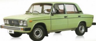
Features of the modification
First of all, the changes affected the engine management system and control instruments. In particular:
- The wiring diagram for Niva 21213 received an additional wiring harness in the engine compartment for connecting a microcontroller and sensors;
- On the Niva model of recent years of production, a more advanced power unit with the VAZ-21214 index is installed. Instead of a carburetor, it has a fuel frame with injectors from GM. The price of a car with injection has increased because of this;
- The instrument panel has changed - the design is borrowed from the VAZ 2108 model.
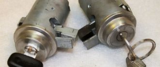
Ignition system
The VAZ 21213 engine uses a non-contact ignition system consisting of:
- ignition distributor sensor (marking 3810.3706). It is responsible for creating control pulses supplied to the electronic switch;
- switch (model marking – 3620.3734) in climatic version U2.1 (corresponds to GOST 15150);
- ignition coils (marking 27.3705).
For reference: this device provides increased spark energy, which helps start the engine in cold weather, and also improves the performance of the power unit when operating the vehicle on low-quality fuel.
Dashboard
A modified instrument panel appeared on the car. In particular, instead of a voltmeter, the manufacturer installed a low battery discharge lamp (no. 12 in the diagram).
Tip: if you often operate your car in off-road conditions, you can buy and connect a voltmeter to the instrument panel yourself. It is more informative than a warning light and will allow you to identify electrical system faults long before the battery discharges.
Motor control circuit
Connection diagram of the VAZ-21214 engine management system with central fuel injection under US-83 toxicity standards with controller 21214-1411010 (EFI-4 type) on VAZ-21214 vehicles:
1 - control lamp “CHECK ENGINE”; 2 – instrument cluster (fragments); 3 – electric fans of the engine cooling system*; 4 – electric heater of the intake pipe; 5 – air temperature sensor; 6 – absolute pressure sensor; 7 – coolant temperature sensor; 8 – block connected to the throttle position sensor; 9 – central fuel injection unit; 10 – block connected to the idle speed regulator; 11 – block connected to the nozzle; 12 – diagnostic block; 13 – controller; 14 – knock sensor; 15 – speed sensor; 16 – oxygen concentration sensor; 17 – adsorber; 18 – battery; 19 – main relay; 20 – fuse block for the engine control system; 21 – relay for turning on the electric fuel pump; 22 – relay for turning on the electric fan*; 23 – relay for turning on the electric heater of the inlet pipe; 24 – electric heater protection fuse; 25 – starter activation relay; 26 – ignition relay; 27 – main car fuse box (fragment); 28 – spark plugs VAZ-21214; 29 – tachometer; 30 – electric fuel pump with fuel level sensor; 31 – ignition module; 32 – crankshaft position sensor; 33 – courtesy light switch, located on the driver’s door pillar; 34 – control unit of the automobile anti-theft system**; 35 – status indicator of the car anti-theft system**; A – wire going to plug “50” of the ignition switch; B – wire going to plug “15” of the ignition switch; B – wire going to terminal “30” of the generator; G – rear wiring harness wires connected to the fuel level indicator; D – rear wiring harness wire connected to switch 33.
Useful: Sensor with car washer fluid level indicator
Connection diagram of the VAZ-21214 engine management system with distributed fuel injection under Euro-2 emission standards with controller 2123-1411020-10 (MP 7.0 type) on VAZ-21214 vehicles:
1 – warning lamp of the engine management system; 2 – instrument cluster (fragments); 3 – electric fans of the engine cooling system; 4 – courtesy light switch, located on the driver’s door pillar; 5 – status indicator of the car anti-theft system; 6 – control unit of the automobile anti-theft system; 7-coolant temperature sensor; 8 – air flow sensor; 9 – throttle unit; 10 – block connected to the throttle position sensor; 11 – block connected to the idle speed regulator; 12 – controller; 13 – oxygen concentration sensor; 14 – knock sensor; 15 – crankshaft position sensor; 16 – speed sensor; 17 – adsorber; 18 – battery; 19 – main relay; 20 – diagnostic block; 21 – fuse block for the engine control system; 22 – relay for turning on the electric fuel pump; 23 – relay for turning on electric fans; 24 – main car fuse box (fragment); 25 – block connected to the additional wiring harness*; 26 – ignition module; 27 - tachometer VAZ-21214; 28 – electric fuel pump with fuel level sensor; 29 – nozzles; 30 – spark plugs; A – rear wiring harness wire connected to switch 4; B – wires connected to plug “1” of fuse block 24 (one wire goes to plug “15” of the ignition switch, and the other to plug “85” of the ignition relay); B – rear wiring harness wires connected to the fuel level indicator.
The order of conditional numbering of plugs in the blocks: a – controller; b – control unit of the automobile anti-theft system; in - air flow sensor; g – speed sensor; d – indicator of the state of the automobile anti-theft system; e – electric fuel pump and oxygen concentration sensor; g – throttle pipe; h – ignition module.
Maintenance Tips
The factory instructions require troubleshooting the ignition system in the following sequence:
Ignition system: wiring for Niva 21213
- From the ignition switch (terminal 15), connect the wire to the coil (terminal +B) to a test lamp;
- Connect its negative terminal to ground;
- Turn on the ignition - turn the key in the lock to position “II”;
- If the control lamp lights up, then the circuit is working. If not, look for damage to the wire;
- With the ignition on, pull out the central wire from the coil from the distributor;
- Bring its metal tip to the cylinder block so that a gap of 3-4 mm forms between them;
- Turn on the starter for a few seconds;
- If the spark jumps, the coil is working.
Tip: you can quickly check the switch in one way - take it from a working car. If the car starts with the new switch, then you need to buy a new one.
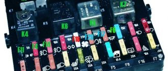
Relays and fuses Niva
The main fuse box is located in the passenger compartment under the instrument panel, to the left of the steering wheel. To access the blocks, pull the latch located on top of the blocks and remove the cover.
- engine control system fuse box;
- windshield wiper relay;
- fuse blocks VAZ-2121;
- engine control system relay block.
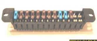
Main fuse box
| Designation and current, A | Protected Circuits |
| F1 (16) | Heater Blower Motor Switch, Tailgate Defroster Switch, Tailgate Wiper Motor, Tailgate Wiper/Washer Switch (Windshield Washer Pump) |
| F2 (8) | Steering column switch, windshield wiper motor, hazard warning switch, breaker relay (in turn signal mode), reverse light switch, instrument cluster (coolant temperature gauge, fuel level gauge, tachometer, indicator lamps: turn indicators, differential locks, parking brake, emergency condition of the service brake system, insufficient oil pressure, fuel reserve, battery charge) |
| F3 (8) | Left headlight (high beam), high beam indicator lamp |
| F4 (8) | Right headlight (high beam) |
| F5 (8) | Left headlight (low beam) |
| F6 (8) | Right headlight (low beam) |
| F7 (8) | Side light lamps in the left front and left rear lights, license plate lights, side light indicator lamp |
| F8 (8) | Side light lamps in the right front and right rear lamps, backlight lamps for the instrument cluster, cigarette lighter, switches, heating and ventilation control unit |
| F9 (16) | Hazard switch, breaker relay (in hazard mode), heated tailgate glass relay contacts |
| F10 (16) | Sound signal, interior lamps, brake lamps in the rear lights |
| F11 (8) | Reserve |
| F12 (8) | Reserve |
| F13 (8) | Fog light relay contacts in rear lights |
| F14 (16) | Cigarette lighter fuse |
| F15 (16) | Reserve |
| F16 (8) | Reserve |
Engine control system fuse box
| Designation and current, A | Protected Circuits |
| F1 (30) | Right electric fan relay contacts |
| F2(30) | Left electric fan relay contacts |
| F3 (15) | Relay windings of the right and left electric fans, controller, injectors, ignition coil |
| F4 (15) | Heating elements for control and diagnostic oxygen concentration sensors, phase sensor, mass air flow sensor, canister purge valve |
On the left under the instrument panel, on the body, there is a block of four fuses for the engine management system and a diagnostic connector. To access the block, unscrew two self-tapping screws and remove the casing.
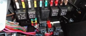
Engine control relay
Below the main fuse box are the engine management system relays.
- ignition relay;
- Niva main relay;
- right electric fan relay;
- left electric fan relay;
- fuel pump relay;
- fuel pump fuse (F5, 15 A).
Relay box under the dashboard
Under the instrument panel, just above the gas pedal, there is a block with four relays.
- Niva rear fog light relay;
- relay for turning on the heated glass of the tailgate;
- low beam headlight relay;
- high beam headlight relay.
Above this block, behind the instrument cluster, there is a turn signal and hazard warning relay.
Blocks for LADA 4X4 2022
The relay and fuse diagram may differ depending on the configuration and production date of the vehicle. Current diagrams of the mounting block are presented in the operating manual as of the date of manufacture of the vehicle.
The fuses are grouped in two fuse blocks located on the left under the instrument panel. The fuse ratings and the circuits they protect are shown in the table.
The fuses for the VAZ 2131 injection system are located in a separate block on the left side under the instrument panel.
The electric motors of VAZ-2121 gearmotors (windshield wipers, tailgate glass, headlights - if installed) are protected by automatic reusable bimetallic fuses. The power supply circuit of the injection system is protected by a fuse-link made of wire with a conductor of reduced cross-section (1 mm2). The battery charging, ignition, engine starting, and “generator – ignition switch – fuse box” circuits are not protected. Powerful consumers (starter, headlights, electric motors Niva 2131 cooling system fans, electric fuel pump, etc.) are connected via a relay.
Mounting blocks for Lada 4×4 2020
https://www.youtube.com/watch?v=SqqIBAU8osQ
The turn signal relay (part number 8450082700, 9-pin), as well as the windshield wiper relay, are located under the trim in the driver’s feet, to the left of the fuse mounting block.
Read news about the new Niva
- Diagram and location of the fuse box Niva VAZ-21213 and 21214
- Diagram and location of the fuse box Niva VAZ-21213 and 21214
- Front lower suspension arms VAZ-2121 - Drawings, 3D Models, Projects, Cars and automotive industry (Car service)
- Timing marks on a Chevrolet Niva car
- Chassis, front suspension, device, Design, operation, description, device, car repair Niva VAZ 2121, engine, assembly, disassembly, transmission, gearbox
- Suspension lift in the field yourself | Niva Repair
- Niva 2121 suspension lift do-it-yourself drawings
- Tuning Niva 2121 with your own hands: body, interior, suspension