Gasoline engines can be equipped with a carburetor or fuel injection system. In the case of a carburetor, it is well known that during operation this system requires periodic adjustment of the idle speed. As for the injector, such a power system operates under the control of the ECU, meaning that there is no need for additional configuration.
However, in practice the situation is somewhat different, since quite often it becomes necessary to adjust the idle speed on the injector. Problems manifest themselves in the form of unstable operation of the internal combustion engine at idle, the speed fluctuates, the engine may stall after starting, overuse fuel if the idle speed is too high, etc.
Next, we will talk about how to adjust engine idle speed on an injection and carburetor engine, and also consider the features and nuances of setting idle speed on engines with the specified fuel supply systems.
Idle system design
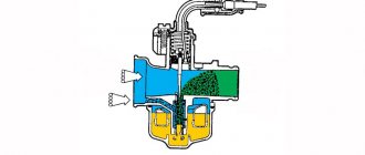
The designs of modern carburetors contain not only the main metering system. It alone would not allow obtaining the necessary mixture composition to maintain normal engine operation in no-load mode, in other words, when the engine should be idling. The system of the same name is responsible for normal operation in idle mode. Let's consider one of the options for its design.
Design of the idle system: 1 - transition hole;
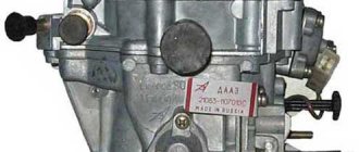
2 - air channel; 3 - idle mixture screw; 4 — hole for low idle speed; 5 - fuel channel; 6 - fuel nozzle combined with an emulsion tube. The idle system includes two fuel supply holes. They have special names: transition hole 1 and low idle speed hole 4 (location options on a real carburetor are shown in the figure below). The transition hole is located under the throttle valve, in close proximity to its trailing edge. The low idle speed hole is located behind the throttle valve, a short distance away at the point where the vacuum is greatest when the throttle valve is closed. This situation is due to the desire to ensure the easiest flow of fuel from the low idle speed hole.
Options for the location of fuel supply holes: 1 - transition hole; 2 - hole for low idle speed
In the fuel supply channel 5 of the idle system there is a nozzle 6, which limits the flow of fuel when idling. In the same channel there is an emulsion tube (often combined with a jet), in which the fuel is mixed with air entering through air channel 2.
Fine-tuning elements include screw 3, which regulates the cross-section of the air channel. In this design, the screw influences the composition of the mixture. Below we will consider a design in which a similar screw regulates the amount of mixture.
Setting up the float mechanism
The level of the fuel mixture in the float chamber is directly related to its quality. At an increased level, the mixture will turn out to be lean, which will negatively affect gasoline consumption and increase toxicity. Without adjusting the floats, the question of how to adjust the carburetor cannot be solved. The process of adjusting the floats includes the following operations:
- Adjusting the floats in relation to the lid and walls of the fuel chamber. If deformation of the float fixing bracket is noticed, it should be aligned manually;
- We adjust the bracket with the needle valve closed;
- We adjust with the float retracted and the valve open; the distance between the float and the valve should in this case be set to about 15 millimeters.
Emulsifying fuel in the idle system
In the idle system, fuel is mixed with a small amount of air, which enters through a special air channel. The fuel emulsification process occurs as follows. When the throttle valve is closed and the fuel mixture is supplied only through the low idle speed hole, the fuel is mixed with air entering not only through the air channel, but also with air from under the throttle valve passing through the transition hole. As the throttle rises, the zone of maximum vacuum moves towards the nozzle of the main dosing system. In this regard, the amount of air entering the idle system through the transition hole is reduced. At some point in the throttle lift, air completely stops flowing from the transition hole, and under the influence of rarefaction, fuel begins to gush through it. At this moment, all air begins to flow only through a special air channel, the throughput of which is regulated by a conical screw.
Causes of failure. Node check
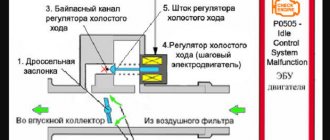
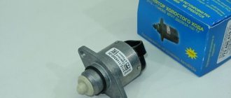
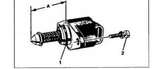
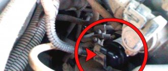
The reasons for the malfunction of the XX regulator are breaks in the electrical winding. engine and needle jamming due to dirt or corrosion. But the sensor is not always the “culprit” for missing idle speed. Therefore, before removing and checking the sensor, check its power supply circuit.
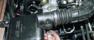
For all checks you will need a multimeter. The power circuit is checked with a device set to “voltmeter” mode. Diagnostics is simple - we disconnect the block with wires from the regulator, connect the “negative” probe of the multimeter to ground, and the positive one to the terminals marked with the letters “A” and “D”. With the ignition on, we take measurements. If the circuit is working properly, the readings should correspond to the rated voltage of the circuit. If there is no voltage, you should check the computer and relays responsible for powering the sensor.
To make it easier to check the sensor itself, remove it from the car. To do this, you only need a screwdriver. To remove a part you need:
- Disconnect the on-board network (remove the terminal from the battery).
- Find the regulator (installed on the throttle assembly).
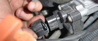
- Disconnect the wiring (after operating the lock).
- Unscrew the two fastening screws;
- Remove the regulator.
The element is checked with the same multimeter, but switched to “ohmmeter” mode. We first connect the probes to terminals “A” and “B”, and then to “C” and “D”. With this measurement, the readings are 50-55 Ohms. Then we connect the probes to terminals “A” and “C”, and then to “B” and “D”. During this test, the ohmmeter shows infinity.
If the readings are correct, there is no break inside the sensor, and its incorrect operation is due to the needle getting jammed.
There is an alternative verification method that does not require the use of measuring instruments. This check is simple:
- Remove the sensor from the car.
- We connect the block with wires back to it.
- We power the on-board network (connect the battery).
- Holding the regulator in your hand, place your finger on it.
- We ask someone to turn on the ignition.
If the element is working properly, when the ignition is turned on, the needle will move, which will be clearly felt by your finger. Needle jamming can be eliminated by washing. For these purposes, use WD-40 or carburetor cleaning aerosol. We use these products to treat the needle and spring. Next, we dry the sensor and check its functionality. If a break in the winding in the regulator is detected or washing does not bring results, we replace the part.
Something else useful for you:
Idle mixture adjustment screw
The final (fine) adjustment of the idle air system is made using a special screw with a conical tip, which regulates the throughput of the air channel of the idle air system. Some carburetor models are equipped with a screw that regulates the amount of fuel, already pre-mixed with air, supplied by the idle system.
Idle mixture adjustment screws. Two screws on the left regulate the amount of mixture, two on the right control the composition of the mixture.
Since in one case the screw regulates the composition of the mixture, and in the other - the amount of the fuel mixture, opposite adjustment methods are used. If the screw regulates the throughput of the air channel, then to enrich the mixture it is necessary to reduce the amount of air by tightening the screw. In order to make the mixture leaner, the screw must be unscrewed. If the screw regulates the amount of fuel supplied, then, on the contrary, to enrich it, it is unscrewed, and to become lean, accordingly, it is tightened.
It is very simple to understand by what principle adjustment is carried out on a particular carburetor. The air adjustment screw is located closer to the carburetor inlet, which is connected to the filter, while the fuel adjustment screw is located closer to the engine mounting flange.
Location of the idle mixture adjustment screws: a — mixture adjustment screw, b — mixture amount adjustment screw
Floating speed with a faulty oxygen sensor
An oxygen sensor, or lambda probe, measures the oxygen content in the exhaust gases and, based on the data obtained, determines the quality parameters of the working mixture, giving a signal to deplete or enrich it. The device works normally only after it warms up to operating temperature - at least 300 degrees. Therefore, most of them are supplemented with an indirect heating system to speed up the process. Failure of heating or contamination of the working surfaces of the sensors with combustion products causes inaccuracies in determining the oxygen content, as a result of which engine operation will be unstable.
Idle jet
If a jet of too large a capacity is installed, the engine begins to operate unstably, slowly picks up speed, and the exhaust sound becomes dull and weak.
If the jet has insufficient flow, the engine revs well, but when the throttle is closed sharply, the revs do not drop as quickly. The reduction in speed to idle occurs with a delay of up to several seconds. Too little throughput leads to unstable operation and frequent engine stops, both in low idle mode and when trying to raise the throttle. Operating the engine with an insufficient idle jet installed can result in the piston sticking to the cylinder wall when the throttle valve is closed. The risk is especially great if the engine has previously been running at full throttle for a long period of time. Under such conditions, after closing the throttle, the engine maintains high speed by inertia. If the idle system is running lean at this point, the heat load increases dramatically due to excessive lean combustion, increasing the risk of overheating and subsequent stalling.
Maintenance and Troubleshooting
Routine work on systems that ensure engine operation should begin with a complete inspection. For convenience, the air filter housing is removed from the carburetor and all air tubes are inspected. There should be no cracks on them, and the material should remain elastic. If necessary, the carburetor is dismantled and completely disassembled with defect detection and replacement of faulty parts.
The next stage involves diagnosing, eliminating identified faults and adjusting the ignition system. It is recommended to clean the contacts in the distributor with fine sandpaper, replace the spark plugs and set the timing correctly. This can be done using a tester or a primitive test lamp. It makes sense to proceed directly to regulating the VAZ 2107 engine only if the carburetor and other systems are in order.
Operation of the idle system in transient mode
When the driver begins to open the throttle slightly, the vacuum in the area of the low idle speed hole decreases.
This leads to a decrease in the supply of fuel through it, so another system must be activated to ensure a smooth transition in operation from the idle system to the main metering system. When the throttle valve rises to approximately 1/4 of the entire stroke, the vacuum in the area of the low idle hole drops so much that the flow of fuel from it stops. The area of maximum vacuum moves closer to the nozzle of the main dosing system, but does not yet reach it. The transition hole is located exactly in this place. Fuel begins to flow out of it in an amount sufficient to ensure a smooth transition in engine operation from idle to partial load mode, when the main metering system is already operating.
Note that the idle jet is important not only for low idle operation, but also for transient operation, since it also regulates the amount of fuel flowing from the transition hole. Along with the jet, operation in transient modes is influenced by the angle of the throttle valve, a special protrusion on the rear of the throttle valve, the shape of the nozzle around the nozzle of the main metering system, and a special groove on the rear edge of the throttle valve.
Throttle valve elements affecting transient behavior. The color indicates the protrusion on the rear of the throttle body (a) and the special groove on the trailing edge (b).
To be continued…
FakeHeader
Comments 31
leave the engine alone =) this is a BSE, slight shaking is normal on it. If the shaking is a little stronger, then first check the oil level, then the spark plugs and so on.
The cure is cleaning the injectors with removal on a stand! See for yourself the amount of dirt, it’s the fault of our valiant advertising gas stations.
I just raised the speed a little and the engine began to jerk less.
The speed is raised with the help of a cord, and not the firmware is changed, I raised it for myself, it seems like there was an effect, but I don’t remember anymore) and the car also twitches at idle, they say that this is normal, but I don’t like it either
I also raised the speed through Vasya, but after about a year everything came back, it somehow works temporarily. Now I just don’t turn off the AC on the climate control and the speed stays on its own, somewhere around 900, there is no vibration, that’s the whole problem)
I don’t turn on the a/c, because the power drops very much and apparently my air conditioner is overgrown with a fungus, a cold is creeping out
The most sensible comments are written below. The rest is some kind of crap!)))
Maybe this post will help? www.drive2.ru/l/6952493/...I solved this problem myself by installing iridium spark plugs - the shaking is almost unnoticeable www.drive2.ru/l/10618436/
for the 1.6 BSE engine this is a normal phenomenon... if you don’t look at the engine running, it doesn’t twitch. most likely it is necessary to “change something in the heads”, and not in the engine =)
This has already been discussed everywhere a thousand times... fortunately there are not many such confused ones =)
I changed the spark plugs. I changed the high voltage wires. I changed the ignition coil.
There is no need to increase the speed, you need to eliminate the cause of the twitching. Look at the spark plug wires and the high-voltage part. It is necessary to treat the cause, not the consequences. I was twitching too, nothing - cured
I had the same problem, I have a 1.8 cdaa engine. I filled it with liquid from LiquiMoly and after rolling the tank, the twitching at idle disappeared, the car began to run smoothly
Procedure
To work, we need a laptop and a diagnostic cable.
Laptop
A laptop or tablet computer running a desktop version of the Windows operating system, as well as special software that is designed specifically for your car brand. Of course, you can connect a desktop computer, but then be prepared to take it outside, directly to the hood of the car.
Diagnostic cable for connection to the ECU
You will also need to purchase a cable to connect the on-board computer to the laptop. As a rule, these cables are divided into several main types, which do not differ very much from each other. Just decide which version of the connector is used in the car. In the oldest models this is the first version, and in newer ones this is the second version of the connector. The port is shaped in such a way that you will not be able to connect it incorrectly.
ELM-327 (bluetooth) - the most popular diagnostic cable among car enthusiasts
ELM-327 (wired version) is an equally popular diagnostic cable among car enthusiasts
As soon as the connection to the on-board computer is completed, in the program running on the laptop, you can view all the parameters of the vehicle’s operation, as well as any errors that arose during the process. Error codes can be found in the documentation accompanying the program or on the Internet.
If necessary, new firmware can be installed on the on-board computer. This is done using the capabilities of the same diagnostic program.
