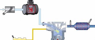
There are quite a few different types of mass air flow sensors (MAF): mechanical (vane type), ultrasonic, hot-wire, etc. We will review the device hot-wire anemometric
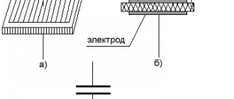
HFM-5 sensor manufactured by Bosch, installed on VAZ cars. The sensor's sensitive element is a thin film on which several temperature sensors and a heating resistor are located. In the middle of the film there is a heating area, the degree of heating of which is controlled using a temperature sensor. On the surface of the film, on the side of the air flow and on the opposite side, two more thermal sensors are located symmetrically, which record the same temperature in the absence of air flow. In the presence of air flow, the first sensor is cooled, and the temperature of the second remains almost unchanged, due to the heating of the air flow in the heater zone. The differential signal of both sensors is proportional to the mass of passing air.
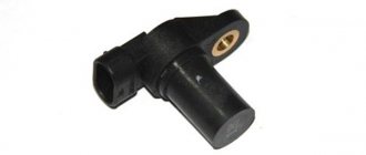
MAF VAZ Bosch
The sensor's electronic circuit converts this signal into a constant voltage proportional to the air mass. This design is called Hot Film (HFM), its advantages include high measurement accuracy and the ability to record reverse air flow, but its disadvantages include low reliability in conditions of contamination and moisture.
In older systems (ECU January-4 and GM-ISFI-2S), other hot-wire mass flow sensors were used, the sensitive elements of which were made in the form of threads. Such sensors are called Hot Wire MAF Sensor. The output signal of these sensors was frequency, that is, depending on the air flow, it was not the voltage that changed, but the frequency of the output pulses. The sensors were less accurate and did not allow registering reverse flow, but these shortcomings were offset by very high reliability.
Mass air flow sensor is a very important sensor in any control system. Based on its signal, the cyclic filling of the cylinder is calculated, which is ultimately converted into the duration of the injector opening pulse.
Several types of sensors were installed on VAZ cars: GM, BOSCH, SIEMENS and Russian. In 1999-2004 two types of sensors 0 280 218-037 and 0 280 218-004 were installed on the VAZ conveyor. These sensors produce different output voltage (calibration) parameters at the same air flow rate and interchange (or rather, replacing 004 with 037, as a rule) is only possible with the replacement of calibration tables in the firmware. The same applies to the new sensor 116, which has been installed as standard since the beginning of 2005.
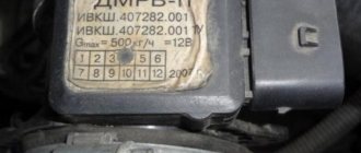
DMRV VAZ 2110
In accordance with the current documentation, three modifications of the air flow sensor HFM5 from BOSCH are allowed for use on VAZ. The VAZ catalog refers to catalogs of spare parts for specific vehicles. Unfortunately, only the last three digits of the “Bosch” catalog number are present on the sensors, and the VAZ number is missing. Historically, the 004 sensor was the first to be introduced in projects with calibrations M1V13O54, M1V13R59, M1V05F05 and M7V03E65 (as well as J5V05F16, the first unofficial version was January 5.1). The first two projects are easily identified by their appearance because... They are without a neutralizer and they used a resonant knock sensor. Then these first two projects were discontinued in production and all further projects (with calibrations of subsequent series) began to be equipped with 037 sensors. Simultaneously with the termination of the two above-mentioned projects, the M7V03E65 project also began to be equipped with an 037 sensor. Modification 037 differs from 004 by modifying the internal air channel of the sensor in order to eliminate air flow pulsations that occur in 004 even with laminar air flow in the intake manifold. At the same time, characteristic 037 has shifted compared to 004. It is believed that in the presence of oxygen feedback, these differences are compensated, which is why the calibration of the M7V03E65 project was not changed when changing the sensor. Since October 2004, the main sensor has been 116. Modification 116 is intended for projects with new generation controllers Bosch M7.9.7 and its domestic analogues - January 7.2, parallel production of which was started by Itelma and Avtel. The calibration of the sensor and its design differ from 004 and 037. The sensor is supplied only assembled, with a code and is marked with a green circle. The element itself has a modified design. In 2006, to complicate the theft or substitution of mass air flow sensor elements, special unidirectional bolts were used to secure the sensing element in the housing. On some classic cars, together with the January 7.2 ECU, Siemens-VDO sensors (5WK97014. AVTEL) were used:
They differ in calibration (from zero volts) and connection diagram. Sensor connection - 1 - 12 volts; 2 - 5 volts; 3 — air flow signal output; 4 — air temperature signal output; 5 is a general minus.
Site about SUVs UAZ, GAZ, SUV, CUV, crossovers, all-terrain vehicles
The mass air flow sensor (MAF) on the ZMZ-409 engine is located between the air filter hose and the intake pipe hose and is designed to convert the air flow entering the engine into DC voltage. Information from the mass air flow sensor allows the control unit to determine the engine operating mode and calculate the cyclic filling of the cylinders with air at steady-state engine operating modes, the duration of which exceeds 0.1 seconds.
Operating principle, general structure and analogues of the UAZ mass air flow sensor with the ZMZ-409 engine.
Depending on the configuration and type of electronic control unit, ZMZ-409 engines can be equipped with mass air flow sensors with a sensitive element made in the form of a conductive film applied to a ceramic base, or in the form of a platinum thread. The sensor signal is a DC voltage whose value depends on the amount and direction of air flowing through the sensor.
The sensor's sensitive element is built on the principle of a thermistor anemometer. It is heated by electric current and its operating temperature is maintained constant. If the air flow through the sensor increases, the sensitive element begins to cool, and the mass air flow sensor control circuit increases its heating current until its temperature is restored to its original level.
Thus, the magnitude of the heating current of the sensitive element is proportional to the air flow. At the same time, the secondary converter of the mass air flow sensor converts the heating current of the element into a DC output voltage.
Structurally, the air flow sensor consists of a plastic body made in the form of a pipe at the ends of which protective grilles are installed. The housing contains a sensitive element, and in the upper part of the sensor there is a secondary converter board closed with a sealed plastic case, and a connector plug, which, depending on the type of sensor, has a different shape and number of pins.
Together with the Mikas 7.2 control unit, mass air flow sensors Bosch HFM5-4.7 0 280 218 037, Siemens HFM62C/11 or NPP AVTEL 20.3855 with a film sensitive element could be installed. With Mikas 11 block - Siemens HFM62C/19 with film or 20.3855-10 with thread sensitive element. With block ME17.9.7 - Bosch HFM7-4.7 0 280 218 220.
External manifestations of a malfunction of the UAZ mass air flow sensor with a ZMZ-409 engine.
A malfunction of the mass air flow sensor on a running ZMZ-409 engine is characterized by an increase in fuel consumption, a significant deterioration in dynamics during acceleration and problems with starting the engine. If a malfunction occurs in the sensor connection circuits or the sensor itself, the on-board self-diagnosis system lights up the Check Engine warning light, which is constantly on when the engine is running, and issues fault codes.
Mikas 7.2
013 - low signal level of the mass air flow sensor (MAF).
Possible causes of the malfunction:
— The mass air flow sensor is not connected to the wiring harness. — open circuit of the sensor power supply. — break in the ground wire of the mass air flow sensor. — the signal wires to the sensor are mixed up or broken. — short circuit of the sensor signal wires. — malfunction of the mass air flow sensor.
014 - high signal level of the mass air flow sensor (MAF).
Possible causes of the malfunction:
— short circuit to the on-board network of the sensor signal wires. — malfunction of the mass air flow sensor.
Mikas 11 and Bosch ME17.9.7
0101 - mass air flow sensor signal output beyond the permissible range 0102 - low signal level of the mass air flow sensor circuit 0103 - high signal level of the mass air flow sensor circuit
Checking the UAZ mass air flow sensor with the ZMZ-409 engine.
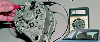
First of all, you need to check that the sensor has power. To do this, you need to disconnect the engine control system wiring harness block from the sensor and, with the ignition on, use a voltmeter to measure the voltage at the terminal (pin number below) of the wiring harness block, while the “negative” probe of the voltmeter must be connected to the vehicle ground:
— Pin “2” for sensor HFM5-4.7 0 280 218 037, HFM62C/11 and 20.3855 — Pin “4” for sensor HFM62C/19 and 20.3855-10 — Pin “3” for sensor HFM7-4.7 0 280 218 220
There should be a voltage of +12 Volts at this pin, otherwise the fault must be looked for in the sensor power circuit. If there is voltage, then the final check is to disconnect the sensor from the wiring harness, turn on the ignition and reset all fault codes, and then start the engine.
If after some time the self-diagnosis system displays a fault code - Low signal level of the mass air flow sensor , then the sensor itself is faulty, and if the code is High signal level of the sensor , then there is a malfunction in the electronic control unit or wiring harness. The mass air flow sensor is not a repairable product, so if it malfunctions, it is replaced with a new one.
Checking the film mass air flow sensor 20.3855.
The general serviceability of the mass air flow sensor 20.3855 with a film sensitive element, which is installed on ZMZ-409 Euro-2 engines with a Mikas-7.2 control unit, can be checked by assembling the circuit shown in the figure below.
When connecting a voltage source of 12 Volts to the circuit, the voltmeter should show 1.3-1.4 Volts, and when the switch indicated in the diagram is turned on for a short time, the voltmeter should show about 8 Volts.
Source
Characteristic
On VAZ cars, the mass air flow sensor is mounted between the air filter element and the throttle hose. Today, products from the manufacturer Bosch are very popular among compatriots. Regardless of whether it is a universal Bosch sensor or, for example, spark plugs, quality from a German manufacturer can always give a head start to domestic products. Let's look at the main characteristics of regulators models 116 and 037.
DMRV 116 is designed to control and convert the air flow that enters the motor into voltage. The data transmitted by the regulator makes it possible to determine the operating mode of the power unit and calculate the cyclic filling of the cylinders with air flow. This filling is carried out in steady-state operating modes of the motor, which last no more than 0.1 seconds.
Let's look at the technical features that Bosch 0 280 218 116 has:
- the regulator operates on the principle of measuring air flow;
- the device provides accurate data, which ensures optimal fuel consumption;
- operating range varies from 8 to 550 kg/h;
- the output pulse level when measuring the range from 0 to 100% will be about 0.05-5 volts;
- As for power supply, the controller is powered from the vehicle’s electrical network, that is, 12 volts is enough for it;
- current consumption is about 0.5 ampere;
- the regulator can function normally in the operating range from 45 degrees below zero to 120 degrees;
- The service life of the Bosch 116 mass air flow sensor is about 3 thousand hours.
As mentioned above, the technical features of the models are the same:
- the operating range for normal operation varies in the region of 8-550 kg/h;
- when operating correctly, the controller will provide accurate data, making it possible to achieve optimal gas mileage (of course, if the engine is running in normal mode);
- since the element is used in a car, it is logical that it should be powered by 12 volts;
- the controller consumes about 0.5 ampere of current;
- the part can operate normally both at 45 degrees below zero and at 120 degrees of heat, this is its operating range;
- service life is at least 3 thousand hours;
- unlike model 116, the new mass air flow sensor 037 during calculations can produce an error of 2.5 percent (both downward and upward).
VAZ air flow sensor pinout. Checking and repairing the air flow sensor
Based on the signal from the mass air flow sensor (MAF), the cyclic filling of the cylinder is calculated, which is ultimately converted into the duration of the injector opening pulse. If it does not work correctly, the car consumes more gasoline than necessary. Such a sensor is installed on the second path, immediately behind the air filter and connected to the electrical system, which is controlled by a six-pin block of wires.
There are quite a few different types of mass air flow sensors: mechanical, ultrasonic, hot-wire and some others.
In this case, we will consider the design of the HFM-5 hot-wire sensor from Bosch, which is most often installed on VAZ cars. The sensor's sensitive element is a thin film on which several temperature sensors and a heating resistor are located. In the middle of the film there is a heating area, the degree of heating of which is controlled using a temperature sensor.
On the surface of the film, on the side of the air flow and on the opposite side, two more thermal sensors are located symmetrically, which record the same temperature in the absence of air flow. In the presence of air flow, the first sensor is cooled, and the temperature of the second remains unchanged, due to the heating of the air flow in the heater zone. The differential signal of both sensors is proportional to the mass of passing air.
- 1 - dielectric diaphragm
- H - heating resistor
- SH - Temperature sensor naked. resistor
- SL - Air temperature sensor
- S1 and S2 - temp sensors before and after the heater.
- QLM - air flow mass
- t—temperature
The sensor's electronic circuit converts this signal into a constant voltage proportional to the air mass. This design is called Hot Film (HFM), its advantages include high measurement accuracy and the ability to record reverse air flow, but its disadvantages include low reliability in conditions of contamination and moisture.
To measure the amount of air that enters the engine means to determine the engine load. When the driver presses the gas pedal, the throttle valve opens and the amount of intake air increases. At the same time, we say that the load has increased. When you release the pedal, the load drops. It's quite simple. However, this is only at first glance. If we take into account the fact that in real driving conditions the engine often changes operating modes and the incoming air in the intake system participates in several gas-dynamic processes, then the problem of measuring the air in the system is not so simple.
In older systems (ECU January-4 and GM-ISFI-2S), other hot-wire mass flow sensors were used, the sensitive elements of which were made in the form of threads. Such sensors are called Hot Wire MAF Sensor. The output signal of these sensors was frequency, that is, depending on the air flow, it was not the voltage that changed, but the frequency of the output pulses. The sensors were less accurate and did not allow registering reverse flow, but these shortcomings were offset by very high reliability.
Several types of mass air flow sensors were installed on VAZ cars: GM, BOSCH, SIEMENS and Russian-made. In 1999-2004 Two types of sensors were installed on VAZ cars: 0 280 218-037 and 0 280 218-004. These sensors produce different output voltage (calibration) parameters at the same air flow rate and interchangeability (or rather, replacing 004 with 037) is only possible with the replacement of calibration tables in the firmware. The same applies to the new sensor 116, which has been installed as standard since the beginning of 2005.
The sensor is supplied only assembled, with a code and marked with a green circle.
On some classic cars, together with the January 7.2 ECU, Siemens-VDO sensors (5WK97014. AVTEL) were used:
They differ in calibration (from zero volts) and connection diagram.
Interchangeability
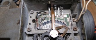
This issue is quite relevant, especially taking into account the cost of original products from the imported automobile industry. But it’s not so simple here; let’s give an example. In the first production models of the Gorky Automobile Plant, the injection Volgas were equipped with a BOSCH air flow sensor. Somewhat later, imported sensors and controllers replaced domestic products.
A – imported filament air flow sensor manufactured by Bosh (pbt-gf30) and its domestic analogues B – JSCB “Impuls” and C – APZ
Structurally, these products were practically no different with the exception of several design features, namely:
- The diameter of the wire used in a wirewound thermistor. Bosch products have a diameter of 0.07 mm, and domestic products have a diameter of 0.10 mm.
- The method of fastening the wire differs in the type of welding. For imported sensors this is resistance welding, for domestic products it is laser welding.
- Shape of a thread thermistor. Bosh has a U-shaped geometry, APZ produces devices with a V-shaped thread, and products from JSC Impulse are distinguished by the square shape of the thread suspension.
All the sensors given as an example were interchangeable until the Gorky Automobile Plant switched to film analogues. The reasons for the transition were described above.
Film air flow sensor Siemens for GAZ 31105
It makes no sense to give a domestic analogue to the sensor shown in the figure, since outwardly it is practically no different.
It should be noted that when switching from filament devices to film devices, most likely, it will be necessary to change the entire system, namely: the sensor itself, the connecting wire from it to the ECU, and, in fact, the controller itself. In some cases, the control can be adapted (reflashed) to work with another sensor. This problem is due to the fact that most filament flowmeters send analog signals, while film flowmeters send digital signals.
It should be noted that the first production VAZ cars with an injection engine were equipped with a filament air flow sensor (made by GM) with a digital output; examples include models 2107, 2109, 2110, etc. Now they are equipped with air flow sensor BOSCH 0 280 218 004 .
To select analogues, you can use information from official sources or thematic forums. As an example, below is a table of the interchangeability of mass air flow sensors for VAZ cars.
Compatibility table for mass air flow sensor for the VAZ model range
The presented table clearly shows that, for example, the MAF sensor 0-280-218-116 is compatible with VAZ 21124 and 21214 engines, but is not suitable for 2114, 2112 (including those with 16 valves). Accordingly, you can find information on other VAZ models (for example, Lada Granta, Kalina, Priora, 21099, 2115, Chevrolet Niva, etc.).
As a rule, there will be no problems with other brands of cars of domestic or joint production (UAZ Patriot ZMZ 409, Daewoo Lanos or Nexia), choosing a replacement mass air flow sensor for them will not be a problem, the same applies to products of the Chinese automobile industry (KIA Ceed, Spectra, Sportage etc.). But in this case, there is a high probability that the MAF pinout may not match; a soldering iron will help correct the situation.
The situation is much more complicated with European, American and Japanese cars. Therefore, if you have a Toyota, Volkswagen Passat, Subaru, Mercedes, Ford Focus, Nissan Premiere P12, Renault Megane or another European, American or Japanese car, before replacing the mass air flow sensor, you need to carefully weigh all the solution options.
If you are interested, you can search online for an epic about an attempt to replace the “native” air meter with an analogue on a Nissan Almera H16. One attempt resulted in excessive fuel consumption even at idle.
In some cases, searching for an analogue one will be justified, especially if you take into account the cost of the “native” VU meter (for example, the BMW E160 or Nissan X-Trail T30).
VAZ 2110 air sensor pinout diagram
- Yellow (closest to the windshield) - mass air flow sensor signal input;
- Gray-white—sensor supply voltage output;
- Green — sensor grounding output;
- Pink-black - to the main relay.
The wire colors may change, but the pin locations remain the same.
Let’s also add that the mass air flow sensor with endings 004, 037, 116 (for Bosch) and 00, 10, 20 (for Pekar) are different in calibration. You can only change it by flashing it.
Connecting the MAF air sensor VAZ 2112
If the mass air flow sensor is operational, then when the engine is running at 900 rpm, the volume of air used will be at least 10 kg per hour. When the speed increases to 2 thousand, this figure will increase to approximately 20 kg. If the volume of air at such speeds drops, the dynamics of the vehicle will also decrease, and accordingly, this will lead to a decrease in gasoline consumption.
If these indicators increase, this will also contribute to an increase in fuel volume. Deviations of the parameter by 2-3 kg should not be allowed, since in this case the operation of the power unit may be incorrect.
Purpose and explanation of the abbreviation
Flow meters, also known as volume meters or mass air flow meters (not to be confused with mass air flow meters and mass air flow sensors), are installed in diesel or gasoline-powered vehicles. The location of this sensor is not difficult to find, since it controls the air supply, you should look for it in the corresponding system, namely, after the air filter, on the way to the throttle valve (DZ).
Installation location of mass air flow sensor on Gazelle 405
The device is connected to the engine control unit. In cases where the mass air flow sensor is in a faulty condition or is missing, a rough calculation can be made based on the position of the air flow sensor. But with this measurement method it is impossible to ensure high accuracy, which will immediately lead to excessive fuel consumption. This once again indicates the key role of the flow meter in calculating the fuel mass supplied through the injectors.
In addition to information from the mass air flow sensor, the control unit also processes data coming from the following devices: camshaft sensor (camshaft sensor), DD (knock meter), remote sensor, cooling system temperature sensor, acidity meter (lambda probe), etc.
Connection diagram for air flow sensor 2114
A common cause of incorrect operation of the mass air flow sensor is the failure of electronic components, which increases the sensor’s response time to changes in air flow. A working sensor monitors changes at a speed of 0.5 ms, and if it breaks down, the response time increases by 20-30 times. The defect is detected only by recording the operation graph with an oscilloscope. Such a sensor cannot be repaired; it must be replaced with a new one.
Troubleshooting methods
There are several options for troubleshooting the device:
- Replacing the sensor. The surest way to ensure normal system operation is to install a known working controller.
- Check the connection of the regulator, as well as the functionality of the electrical circuit. It is very rare, but it happens that the regulator refuses to work normally due to oxidation of the contacts on the connector. In this case, you can try to disconnect the sensor and clean the contacts with an iron brush.
- Rinse the device. This option for restoring performance is considered one of the most popular among our compatriots today. Cleaning usually takes a little time, but you have every chance of restoring the functionality of the regulator. Our resource has already written about flushing the device; detailed step-by-step instructions are presented in this article.
Checking the air sensor yourself
When a malfunction of the mass air flow sensor occurs, the air-fuel mixture becomes over-rich or lean, which immediately affects the operation of the engine and may ultimately result in engine failure.
Symptoms of a malfunctioning mass air flow sensor:
- Check Engine error appears;
- Increased fuel consumption;
- Doesn't start well when hot;
- The car began to accelerate slowly;
- Engine power lost.
The easiest way to check the mass air flow sensor on a VAZ 2114 is to disconnect the plug. If there is no signal, the engine control unit goes into emergency operation mode, determining the approximate air volume based on the throttle position. At the same time, fuel consumption increases slightly - for the VAZ 2114 it reaches 10-12 liters per 100 km. A characteristic feature is the increase in idle speed to 1500 rpm. But when using a January 7.2 or Bosch M7.9.7 controller, the idle speed does not increase due to the software features.
The normal voltage at the output of the new sensor is 0.996 - 1.01 Volts. During operation, it gradually changes and, as a rule, increases. The greater the value of this voltage, the greater the wear of the mass air flow sensor.
Here is the reference voltage in volts:
- 1.01 - 1.02 - good condition of the sensor.
- 1.02 - 1.03 - not a bad condition.
- 1.03 - 1.04 - the resource of the mass flow sensor is coming to an end.
- 1.04 - 1.05 - emergency condition.
- 1.05 and above - it’s time to replace the mass air flow sensor.
The measurement is made between the yellow and green wires. Voltage values can be displayed on the screen of some on-board computers (menu voltage from sensors, U Mass air flow sensor).
Important: the limits and fluctuations of the output voltage in at least 30% of cases for a faulty sensor will be NORMAL and will not cause the “Check” icon on the panel. That is, voltage measurements are not very informative, but the rate that it will produce in kilograms of air will correspond to the movement not where it actually is, and the ECU will interfere with the mixture based on it - hence the extra consumption!
You need to check the sensor at a service center, preferably with a proprietary scanner, which itself indicates by blinking if there is a imbalance in some parameter (in this case, air flow in kilograms), comparing it with the reference values stored in its memory.
Basic faults
There is practically nothing to break in a film sensor, so they are considered “eternal”. The spiral of filament air flow sensors is less reliable, however, these electronic devices cannot be repaired in principle, with the exception of cleaning and replacement. The following symptoms will help determine the malfunction of this particular sensor:
- spontaneous decrease in engine power;
- decreased acceleration dynamics;
- engine not ;
- increase in fuel consumption unjustified by driving style;
- illuminated Check errors;
- change in XX speed in any direction, appearance of jerks;
- The car stalls when changing gears.
When diagnosing a low signal level, the following options are possible:
- the plug fell off;
- the power supply is broken;
- oxidation or loss of mass;
- signal wire break.
Rice. 10 Mechanical damage to the VU meter
Since the electrical device is not repairable, but has a simple design, diagnostics can be performed on your own according to the principle of increasing its complexity.
Replacing the sensor - instructions
Using a screwdriver, unscrew the clamp of the air intake corrugation at the sensor outlet, pull it off and carefully inspect the internal surfaces of the sensor itself and the corrugation. These surfaces must be dry and clean; traces of condensation and oil are unacceptable. If the air filter is changed rarely, then dirt getting on the sensitive element of the sensor is the most common cause of its breakdown in VAZ cars.
There may be oil in the mass air flow sensor as a result of an increased oil level in the engine crankcase, or the oil sump of the crankcase ventilation system is clogged.
Next, unscrew the 2 screws of the sensor with a 10mm wrench and remove it from the air filter housing. There should be a rubber sealing ring on its front part (at the entrance edge). It prevents unfiltered air from being sucked into the intake tract through the sensor.
If the ring is out of place and stuck somewhere in the air filter housing, then there will be a thin layer of dust on the inlet mesh of the sensor itself. This is the second reason that destroys the mass air flow sensor ahead of time.
Correct assembly should take place in the following sequence: put a sealing rubber band on the sensor, check the sealing skirt, then insert everything together into the filter housing.
This concludes the visual check of the mass air flow sensor at home. You can check its operation 100% only with the help of special equipment in a car service center. For example, using a technique for assessing the oscillogram when the throttle is sharply opened to the cutoff mode (a motor tester is needed), or assessing the oscillogram when the ignition is turned on.
Resuscitation of a damaged air flow sensor is successful in no more than 5% of cases. In extreme cases, you can rinse with ethereal liquid to clean matrices and optics. It will evaporate without a trace. After making sure that there is no more dust or debris in the device, you can dry it thoroughly and put it back in place. Sometimes after such a simple procedure the device will work.
On most foreign cars, a mass air flow sensor was installed until 2000; subsequent generations of models began to be equipped with a pressure controller. Replacing a non-working sensor is simple and can be done on your own without any problems, you just need to buy a mass air flow sensor that matches the ECU firmware version. Its price is around 3,000 rubles, depending on the manufacturer.
Source
Installation location
To save fuel, modern cars are equipped with injection engines with electronic ignition. In a simplified form, an injector is a point injection of a mixture through a nozzle into a cylinder or intake tract. The ECU control unit is usually called the “brains” of the car; it is this body that adjusts the four main parameters of the electronic control system (ECM):
- injection frequency;
- injection moment;
- fuel mixture dose;
- the ratio of fuel and air in it.
To obtain this data, the principle of remote sensors is used. For example, the moment of injection is determined by the readings of the crankshaft sensor DPKV, and the mass air flow sensor is responsible for the proportions of the mixture. All air entering the car engine passes through the throttle valve, which is located between the intake manifold and the air filter.
Therefore, it is most logical to look for the mass air flow sensor directly in front of the throttle valve, where it is located. Attention: Information is transmitted to the controller from seven sensors: camshaft DRV, detonation DD, lambda probe, throttle valve DPZ, cooling system DTOZh, volume meter DPKV and crankshaft DPKV. Based on these signals, the ignition module is turned off, the fuel pump and injectors, the fan and the idle regulator are turned on.