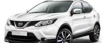
Skoda Rapid
— five-door liftback, belongs to golf class cars. Produced since 2013. In Russia and the CIS countries, official deliveries were carried out in 2014, 2015, 2016, 2022, 2022, 2019, 2022, 2022 and to the present. Rapid is sold with both gasoline and diesel engines. In our material we will present a description of the fuses and relays of the Skoda Rapid. We will show you the places where the blocks with fuses and relays are located, their photographs and diagrams with decoding of the elements. Let's highlight the fuse responsible for the cigarette lighter and windshield washer.
The purpose of the fuses and their number depends on the year of manufacture and the level of electrical equipment of the Skoda Rapid. In case of difficulty, please contact your nearest dealer.
Fuses for Skoda Octavia A5
The power supply circuits for electrical equipment of the Skoda Octavia A5 are protected by fuses and relays. The fuses are installed in two mounting blocks: one is located in the passenger compartment, the second in the engine compartment.
Before replacing a blown fuse, find out the cause of its failure. To remove, use the special tweezers included in each block. Replace the blown fuse with a fuse of the same rating. Depending on the maximum current, all fuses are painted in different colors.
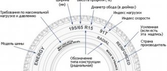
Fuse color coding
| light brown | 5 |
| brown | 7.5 |
| red | 10 |
| blue | 15 |
| yellow | 20 |
| white | 25 |
| green | 30 |
| orange | 40 |
| red | 50 |
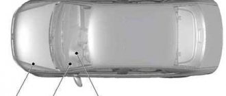
Fuse box in the passenger compartment
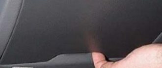
The fuses in the Skoda Octavia A5 interior are located under the cover on the left side of the front panel. You can open the cover using a screwdriver, which is inserted into a special groove.
Review of Probable Causes
So, first of all, let’s talk about what became the “culprit” for the improper operation of the dimmer.
Most often, the dimmer stops working after a light bulb in a chandelier or floor lamp burns out. At the moment of burnout, a short circuit may occur, as a result of which one of the most important circuit elements in the dimmer, the triac, burns out. If the triac does not work, the entire circuit fails.
The second reason why the device may not turn on, or vice versa, may not turn off the light, is that the dimmer works with an energy-saving lamp. We have already talked about the fact that for LED and fluorescent lamps you need to buy special dimmers, specifically designed to work with “housekeepers”.
What to do so that the device can adjust the brightness of the light
Another probable cause of the malfunction is incorrectly selected dimmer power, as a result of which it does not work as it should. We have already said more than once that the power of the dimmer should be 30-50% greater than the power of all the light bulbs it regulates.
If you missed this point and inserted too powerful light sources into the lamp, it is not surprising why the dimmer does not turn off the light or adjust the brightness of the lamps. We talked about how to choose a dimmer in a separate article. Well, the last thing that needs to be said is that perhaps the problem is in the electrical wiring on the site: the chandelier-switch.
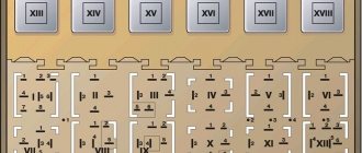
Block in the cabin
The fuse box is located under the instrument panel and is covered with a protective cover.
Option 1. Models before 2015.
Photo
Scheme
Description
| 1 | 5A Contact S |
| 2 | 5A START/STOP system |
| 3 | 7.5A Instrument cluster, headlight range control, telephone, oil level sensor |
| 4 | 5A ABS/ESC control unit |
| 5 | 5A Petrol engine: cruise control |
| 6 | 10A Reversing light (manual gearbox) |
| 7 | 10A Ignition, engine control unit, automatic transmission |
| 8 | 5A Brake pedal limit switch, clutch pedal switch, radiator fan |
| 9 | 5A Heater control, climate control unit, parking assistant, power windows, radiator fan, washer nozzles |
| 10 | DC/DC converter |
| 11 | 5A Mirror adjustment |
| 12 | Trailer recognition control unit |
| 13 | 10A Automatic transmission control unit, automatic transmission selector |
| 14 | 10A Headlight range control |
| 15 | not used |
| 16 | 5A Power steering, speed sensor, engine control unit |
| 17 | 10A Head unit (Start-Stop), daytime lighting mode |
| 18 | 5A Heated mirrors |
| 19 | 7.5A Ignition switch |
| 20 | 15A Engine control unit, fuel pump control unit, fuel pump |
| 21 | 10A Reversing light (automatic transmission), fog lights with CORNER function |
| 22 | 7.5A Heater control, air conditioning control unit, telephone, instrument cluster, steering angle sensor, multifunction steering wheel, ignition key removal lock |
| 23 | 15A Lighting of the interior, glove box and luggage compartment, side lights |
| 24 | 5A Central control unit |
| 25 | not used |
| 26 | 15A Rear window wiper |
| 27 | not used |
| 28 | 10A Petrol engine: canister solenoid valve, additional electric heater RTS |
| 29 | 10A Injection, coolant pump |
| 30 | 20A Fuel pump, ignition, cruise control |
| 31 | 10A Lambda probe |
| 32 | 20A injection pump, pressure valve |
| 33 | 20A Engine control unit |
| 34 | Engine control unit, vacuum pump |
| 35 | 5A Switch illumination, license plate light, parking lights, headlight cleaning system |
| 36 | 15A High beam |
| 37 | 5A Rear fog lamp, DC/DC converter |
| 38 | 10A fog lights |
| 39 | 30A Heater fan |
| 40 | not used |
| 41 | 20A Heated front seats |
| 42 | 30A Heated rear window |
| 43 | 15A Horn |
| 44 | 30A Windshield wiper |
| 45 | 20A Tailgate lock, central locking |
| 46 | 7.5A Alarm |
| 47 | 15A Cigarette lighter fuse , socket in luggage compartment |
| 48 | 15A ABS |
| 49 | 15A Direction indicators, brake lights |
| 50 | 10A DC/DC converter, head unit |
| 51 | 30A Power windows (driver's door + rear left door) |
| 52 | 30A Power windows (front passenger door + rear right door) |
| 53 | 15A Washer |
| 54 | 5A Start-stop system instrument cluster, steering column switch unit, multifunction steering wheel |
| 55 | 30A BU automatic transmission |
| 56 | 25A Headlight washer |
| 57 | 15A Low beam left headlight |
| 58 | 15A Low beam right |
In this version, fuse number 47 is responsible for the cigarette lighter, and fuse number 53 is for the washer.
Option 2. Models from 2022.
Photo - example
Fuses on Skoda Rapid: diagram where they are located
— five-door liftback, belongs to golf class cars. Produced since 2013. In Russia and the CIS countries, official deliveries were carried out in 2014, 2015, 2022, 2022, 2022, 2019, 2022, 2022 and to the present. Rapid is sold with both gasoline and diesel engines. In our material we will present a description of the fuses and relays of the Skoda Rapid. We will show you the places where the blocks with fuses and relays are located, their photographs and diagrams with decoding of the elements. Let's highlight the fuse responsible for the cigarette lighter and windshield washer.
The purpose of the fuses and their number depends on the year of manufacture and the level of electrical equipment of the Skoda Rapid. In case of difficulty, please contact your nearest dealer.
Wiring diagram Skoda Rapid
Did not find an answer to your question? We invite you to familiarize yourself with the electrical diagram of the Skoda rapid car in pdf format: “download“.
p, blockquote 34,0,0,0,0 —>
p, blockquote 35,0,0,0,0 —> p, blockquote 36,0,0,0,1 —>
That's all. And if you have anything to add, write in the comments.
Recording for yourself and for those who are interested and may find it useful. Made in a way that is convenient for visual perception. If someone doesn’t like this display, there is the original Excel file, take it, correct it, make it your own. All data was collected in the vastness of Drive and only what I needed at the moment to connect additional sources was selected. I am posting a full screenshot of the file and the file itself. If you have any additions, tell me, I’ll add them.
Z.Y. All data on the Activ configuration. Other configurations may differ (where in the second column I have “no”, yours may use it). The lines highlighted in red are most likely not used in all trim levels (90% sure). Lines highlighted in green, power appears after turning on the ignition. In more complete configurations, fuses No. 27 and No. 37 can be used. In the fuses, where power appears after ignition, a voltage drop occurs when the car is started.
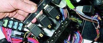
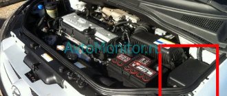
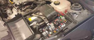
Block under the hood
Option 1. Models before 2015.
In the engine compartment, this block is located on the positive terminal of the battery and consists of 2 sections (fuse section and high power fuse section.) Depending on the engine version, the 1st block can be located either to the left or to the right of the battery.
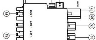
Scheme
Purpose
| 1 | 175A Generator |
| 2 | 80A not used |
| 3 | 60A Salon (option 1), Power supply to fuse box (option 2] |
| 4 | 40A Additional electric heater (option 1) Interior (option 2) |
| 5 | Salon |
| 6 | Radiator fan, pre-glow system control unit |
| 7 | Electro-hydraulic power steering |
| 8 | 30A ABS |
| 9 | Radiator fan |
| 10 | Automatic transmission |
| 11 | 5A ABS |
| 12 | 40A Central control unit |
| 13 | Additional electric heater |
Location of modules and provision of access to them
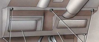
The modules of these devices in Skoda Octavia A5 (A7, Tour) cars are located in the engine compartment and in the cabin. To access devices located in the engine compartment, you need to lift the hood cover and lock it. If you look at the car from the front, the fuse box is located on the right near the front pillar of the car. In order to remove the top plastic cover of the module, you need to move two brackets in the downward direction and pull the part towards you.
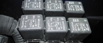
In addition, the described module also contains two relays - the electric motor of the Skoda cooling system fan and the automatic transmission control.
The fuse box, which is located in the passenger compartment, can be found at the end of the front console. To do this, you need to open the front driver's door and use a flat-head screwdriver to pry off the module cover from the bottom.
After 2015
In a left-hand drive cabin.
In a right-hand drive cabin.
| In the showroom since 2015. | |
| Number | Protected circuit |
| Headlights on the left | |
| central locking | |
| Ignition system relay | |
| Headlights on the right | |
| Driver's door power window | |
| Central control unit - interior lighting | |
| Sound signal | |
| Towbar - left light | |
| Steering column lever, engine control unit (only vehicles without KES5Y), automatic transmission (only vehicles without KESSY), automatic transmission selector lever (only vehicles without KESSY), ESC (only vehicles without KESSY), trailer hitch (only vehicles without KESSY), power steering (only vehicles without KESSY) | |
| Rear left door power window | |
| headlight washer | |
| Head unit display, navigation | |
| Taxi equipment | |
| Steering column lever, light switch, ignition key removal lock (vehicles with automatic transmission), light signal, SmartGate system, rain sensor | |
| Air conditioning, automatic transmission selector lever, diagnostic connector | |
| Instrument cluster | |
| Alarm, sound signal | |
| No | |
| Windshield and rear window washer | |
| Heated front seats | |
| Air conditioning fan, heater, air conditioning system | |
| Reserve | |
| Front seat heating button | |
| Rear window wiper | |
| Reserve | |
| Airbag | |
| Power windows, light switch, reverse light switch, air conditioning, parking assist, outside rearview mirrors, center keypad power, side keypad power, interior rearview mirror | |
| Fuel pump, radiator fan, cruise control, windshield and rear window washer relay coil | |
| Diagnostic connector, headlight range control, steering column switch, interior lighting | |
| Starter Relay Coil, Clutch Pedal Switch | |
| Heated windshield washer nozzles | |
| Not used | |
| Radar | |
| Reserve | |
| Additional electric heater | |
| Reserve | |
| Heated rear window | |
| Power window for front passenger door | |
| Towbar - contact in socket | |
| Cigarette lighter, 12 V socket | |
| Rear right door power window | |
| Front and rear window washer, steering column lever | |
| Towbar - contact in socket | |
| Towbar - right light | |
| Gasoline pump | |
| Head device | |
| Heated exterior mirrors | |
| KESSY | |
| Steering column lock (KESSY) | |
| ABS or ESC | |
| No |
Purpose
The layout of safety elements is quite extensive and to accurately determine the location of a particular device, it is necessary to carefully study their features and characteristics. Thus, the safety element module, which is located in the passenger compartment of the A5 (A7, Tour), provides protection for such electrical circuits as the ABS and ESC control module, airbag circuits, climate control and heating circuits, automatic transmission control, rear window wiper, heating seats and central light switch. The circuits listed are equipped with 5 amp fuse elements. 10-amp devices provide protection for the central locking control, light switch, and powertrain control module. 20-amp are used in the circuit of the trunk socket (not to be confused with the trunk lighting), and the lighting washer circuit. The complete diagram is shown in the illustration below using the Skoda Octavia Tour 1.6 model as an example.
The safety element module, which is located in the engine compartment of Octavia models (including Tour), is equipped with fewer devices. Thus, 5-amp protect the electrical circuits of the diagnostic wire, the turn signal and windshield wiper switch levers, the power unit control module, and the clutch pedal switch. 10 amp cells are used in the cooling fan, exhaust gas circulation valve, secondary air pump, and fuel pump circuits. 15-amp protect the circuit of the lambda probe, horn, automatic transmission control unit, trunk lighting.
The ignition, on-board network control module and right-hand lighting fixtures of Octavia models are protected by 20-amp devices. Higher load circuits such as the starter, power terminals, ABS valves are equipped with 30 to 50 amp circuit breakers.
A complete map of the location of fuses in Skoda Octavia A5 / 7, (Tour) cars can be found in the vehicle’s operating manual or in special teaching aids.
Replacing fuses inside the Skoda Rapid: briefly about the main thing
To replace a blown fuse inside the car, you will need 10 minutes of free time, and all you need to do is take a slotted screwdriver and pliers. To change the device you need to:
There may be several consumer devices per fuse, or several fuses may be installed per device. In order to completely disconnect the equipment, it is recommended to check the wiring diagram in the vehicle's technical book or test the contacts with a multimeter.
It is also important to know that, depending on the configuration of the Skoda Rapid, 2 options of the block panel can be installed in the car, differing in the number and arrangement of elements in the device. The plastic panel is mounted by lightly pressing along the entire perimeter until the characteristic sound of the latches clicking into place.
Cigarette lighter modification
Some drivers upgrade the device by installing an additional connector. To do this you will need to acquire a tool.
- Drill or screwdriver with a set of metal drills.
- A crown for cutting a hole, the diameter should match the diameter of the car cigarette lighter.
- File.
- Soldering iron with solder.
- Wire cutters.
- Screwdrivers.
- Multitester.
- Heat-shrink tubing.
- Wire of suitable cross-section. You should take extra cables to avoid the possibility of melting. The optimal cross-section would be 1.5-2 mm.
- A fuse that can withstand the amperage recommended by the vehicle cigarette lighter manufacturer.
Next, we proceed to installing the additional device ourselves.
- We turn off the power to the car and select a place to connect an additional car cigarette lighter. It is advisable that it be a flat panel - the device will not stick to corrugated or curved surfaces.
- We drill a hole of a suitable diameter and clean the edges with a file.
- We connect to the wiring by following the pinout and passing through the fuse.
- We check the functionality of the model and carry out assembly.