Nissan Qashqai
- a compact crossover that went into production in 2006.
Qashqai+2 is a 7-seater version of the Qashqai, with an extended wheelbase.
In the USA it is known as Rogue Sport. The first generation is designated j10 and was produced in 2007, 2008, 2009, 2010, 2011 and 2012. The second is designated j11 and was produced in 2013, 2014, 2015, 2016, 2022, 2022, 2022, 2022. This material will provide information describing the fuse and relay blocks of the first and second generation Nissan Qashqai, with diagrams, photographs and designations of elements.
We will separately highlight the fuses responsible for the cigarette lighter.
Please note that the design options of the blocks, the number of their elements, as well as the diagrams may differ from those presented and depend on the country of delivery, year of manufacture and equipment of a particular vehicle. Check the description with yours, it will be printed on the protective cover of the unit.
j10
Block in the cabin
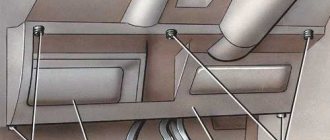
It is located in the instrument panel. To access, simply pull the cover.
Photo of the block
Description
| F1 | 10A Audio system, electric exterior mirrors |
| F2 | 15A Front socket (cigarette lighter) |
| F3 | Reserve |
| F4 | 10A Air conditioning, electric interior heater |
| F5 | 15A Heater electric motor |
| F6 | 15A Heater electric motor |
| F7 | 10A Additional equipment |
| F8 | 15A CVT sensors (manual gearbox) |
| F9 | 15A Audio system |
| F10 | 10A Brake Light Bulbs |
| F11 | Reserve |
| F12 | 10A Interior electrical control unit |
| F13 | 10A Electrical equipment |
| F14 | 15A Rear socket (if installed) |
| F15 | 10A Heated mirrors |
| F16 | 10A Interior electrical control unit |
| F17 | 15A Electrical equipment |
| F18 | 20A Moto windshield wiper gearbox |
| F19 | 10A Airbag SRC system |
| F20 | 10A Heated seats |
| R1 | Relay additional interior equipment |
| R2 | Heater fan relay |
Fuse number 2 at 15A is responsible for the front cigarette lighter. In the diagram in English it is designated as - POWER SOCKET.
Blocks under the hood
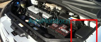
In the engine compartment there are 3 blocks with fuses and relays.
Block - A
To gain access, press the side latch of the cover and pull it out.
Photo - diagram
Designation
| F1 | 15A Glass heater |
| F2 | 15A Glass heater |
| F3 | 15A Fog lights |
| F4 | 30A Windshield wiper |
| F5 | 15A Low beam lamp, right headlight |
| F6 | 15A Left headlight low beam lamp |
| F7 | 10A Right headlight high beam lamp |
| F8 | 10A Left high beam lamp |
| F9 | 10A Side light bulbs |
| F10 | Reserve |
| F11 | 15A Transmission control |
| F12 | 20A Engine control unit |
| F13 | 10A Air Conditioning Compressor |
| F14 | 10A Reversing lamps |
| F15 | 10A Gearbox |
| F16 | 10A Engine control system |
| F17 | 15A Fuel pump |
| F18 | 10A Power system (fuel injectors) |
| F19 | 10A Hydro electronic unit ABS |
| F20 | Reserve |
| R6 | Ignition system relay |
| R8 | Tailgate defroster relay |
| R16 | Engine cooling fan low speed relay I |
| R17 | Engine Cooling Fan High Speed Relay II |
Block - B
You can open the second block in the same way.
Photo
Purpose
| F1 | 20A Air cooler turbine (turbodiesel) |
| F2 | 10A Transmission mode switch block (vehicles with all-wheel drive) |
| F3 | 10A Generator |
| F4 | 10A Horn |
| FL5 | 60/30A Electric power steering, headlight washer pump, ABS system |
| F6 | 40A ABS system, stability control system |
| F7 | 30A Electric interior heater (for a car with a diesel engine) |
| F8 | 30A Electric interior heater |
| F9 | 30A Electric interior heater |
| F10 | Reserve |
| FL11 | 50/30/40A Engine cooling fan, ignition |
| F12 | 40A Interior electrical control unit |
| R3 | Horn relay |
| R4 | Engine Cooling Fan Relay |
| R5 | Headlight washer pump relay |
Block - B
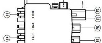
It is located on the positive terminal of the battery and consists of high power fuse links.
j11
Blocks in the cabin
They are located on the front side of the instrument panel.
Right block (may be missing)
- Left block (main)
- Example location
- Photo
- The top row is spare fuses.
- Diagram from the back of the cover
- Purpose of elements
- Numbering from left to right, from top to bottom.
- 15A Windshield washer
- 10A Airbags
- 5A Instrument panel
- 10A Ignition system
- 10A VDC (stabilization system, exchange rate control)
- 15A Heated seats
- 20A Fan
- 5A Illumination of instruments, buttons, glove compartment
- 20A Reserve
- 15A Glass heater
- 15A Glass heater
- 10A Mirrors
- 10A Stability control
- 10A Electrical devices
- 15A Front cigarette lighter
- 10A Reserve
- 20A Fan
- 10A Reserve
- 20A Audio system
- 5A Electrical components
- 10A Instrument panel
- 10A Interior lighting
- 20A Reserve
- 10A Stop lights
- 10A Immobilizer Antenna
- 5A Switch, clutch sensor
- 10A BMC
- 10A Electrical components
- 20A Power supply opening/closing doors
- 15A Windshield wipers
- 15A Rear socket (cigarette lighter)
- 15A Hazard alarm, turn signals
The cigarette lighters are controlled by fuses 15 (front) and 31 (rear) at 15A.
- The individual relay elements are located on the reverse side of the block.
- Ignition system relay
- Front Engine Fan Relay
- Rear fog lamp relay
- Auxiliary relay
Blocks under the hood
Mounting blocks
They are located in the engine compartment under the air intake pipe. An example of access is shown in the figure.
- Photo of the 1st mounting block
- Description of the 1st mounting block
- Scheme
- Translation of symbols in Russian
| 81 | 10A Engine control unit |
| 82 | 15A Engine control unit, |
| 83 | 15A Throttle valve, engine control unit, canister valve (EVAP), mass air flow sensor, ignition coils, main relay, exhaust valve, intake valve, high pressure fuel pump, injectors, engine compartment fuse box, air-fuel ratio sensor, heater fuel, water in fuel sensor, coolant bypass valve |
| 84 | 10A Engine control unit, intake manifold valve, timing exhaust valve, timing intake valve, timing intermediate valve |
| 85 | 15A Air-fuel ratio sensor, heated oxygen sensor, turbocharging valve, engine control unit, glow plug control unit |
| 86 | 15A Injectors, ignition coils, fuse box |
| 87 | 15A A/C compressor relay |
| 88 | Not used |
| 89 | Not used |
| 90 | 30A Front Wiper Relay, Front Wiper Motor |
| 91 | 20A Fuel pump relay |
| 92 | Not used |
| 93 | 10A Engine Control Module, Transmission Control Module, Transmission Range Sensor, Engine Compartment Fuse Box, Neutral Position Sensor, Primary Speed Sensor, Secondary Speed Sensor, RPM Sensor, Reverse/Neutral Sensor |
| 94 | Not used |
| 95 | 5A Steering wheel lock block |
| 96 | 10A Restart relay (start-stop) |
| 97 | 10A Front Right Combination Lamp, Front Left Combination Lamp, Compressor, Transmission Range Sensor, Engine Compartment Fuse Box, Neutral Position Sensor, Reverse Speed Switch, Reverse/Neutral Sensor |
- Photo of the 2nd mounting block
- Description of the 2nd mounting block
Blocks under the headlight
- They are located under the left headlight, behind the bumper.
- Block 1 - example photo
- Example of the 1st block diagram
- Block 2 - photography
- Diagram of the 2nd block under the headlight
- Designation
| HEATED SCREEN | Heated glass |
| H/LAMP WASHER RELAY | Headlight washer relay |
| ANTI THEFT HORN RELAY | Anti-theft horn relay |
| HEATED FRONT SCREEN RELAY | Heated windshield relay |
Battery block
- Located on the positive terminal of the battery.
- Scheme
- If you have something to add, write in x.
Source: https://vsepredohraniteli.ru/nissan/qashqai.html
Heater fan fuse Nissan Qashqai
The heater fan fuse (two fuses, as always with Nissan) are located in the fuse box in the passenger compartment. At the bottom of the panel, to the left of the steering column. Fuses number 15 and 16 are fifteen amps. Be sure to change two fuses.
Fragment of a diagram of a Qashqai heater fan with automatic control. The rotation speed of the fan motor is controlled here using a power transistor.
And a fan control circuit in the version with manual climate control. In this case, the speed is controlled using a set of resistors. Please note that in position 4 of the regulator, power is supplied directly to the stove fan. If the heater fan on your Qashqai only works at speed 4, it makes sense to immediately remove the regulator, most likely the thermal fuse in it has burned out.
And the location of the heater fan on the Nissan Qashqai.
Source: https://aelectrik.ru/stati/predokhranitel-ventilyatora-pechki-ni/
When should the installation be done?
Fuses do not have an expiration date, so they need to be changed as needed. For example, if the headlights cannot be adjusted, the light has become dim, it would not hurt to look into the fuse box and at the same time check whether the car is producing the correct voltage.
If the cigarette lighter fails and stops heating, it also wouldn’t hurt to check the fuse. If there is no light in the cabin, most often the culprit is not burnt-out lamps, although they should also be checked, but a burnt-out fuse element. It can also cause the cooling fan to fail. Before disassembling or replacing any device, you need to look into the unit and check if they are all working properly.
The location of the fuses plays an important role. You can't swap them or confuse them. When replacing several, remove them one at a time so as not to violate the rating. Different appliances require different power supplies.
Deciphering it on a paper diagram will help you understand which block is responsible for which devices. The color of the item may differ if you have already replaced it and installed another one, but with the same value.
Nissan Qashqai fuses
Salon power supply
Modern cars have fairly easy access to these elements. In addition, the Nissan Qashqai fuse diagram is indicated directly on the block cover, which simplifies working with the elements. Therefore, below we will describe which fuse is responsible for what. The interior kit is located at the bottom left of the dashboard and can be opened simply by moving your fingers.
Below is the purpose of each fuse in circuit order:
- Audio system, drive external mirrors.
- Front socket.
- Spare.
- Air conditioning system, interior heating.
- Electric heater drive.
- Repeat number 5.
- Additional equipment.
- With manual transmission - CVT sensor.
- Audio (-).
- Stop lights.
- Spare.
- equipment control.
- Salon equipment.
- If available, there is a rear socket.
- Heated mirrors.
- Equipment control unit.
- Equipment.
- Windshield wiper motor.
- Airbags.
- Heated seats.
- Relay 1 – additional interior equipment.
- 2 – heating fan.
Rear under the hood
To get to it, you need to remove the air intake, open the cover and disconnect the power wire terminals to get to the fuses themselves.
Element markings:
- Turbodiesel or air cooling turbine.
- With all-wheel drive - transmission switching unit.
- Generator.
- Klaxon.
- Power steering, optics washers (pump), ABS.
- ABS, exchange rate stabilization system.
- With a diesel internal combustion engine - interior heating.
- Repeat number 7.
- Repeat number 7.
- Spare.
- Engine cooling system fan, ignition.
- Cabin equipment management.
- Relay 3 – horn.
- 4 – fan of the internal combustion engine cooling system.
- 5 – headlight washers.
Front power supply under the hood
It is actually located next to the front block. The cover is also removable. In addition to fuses and relays, it contains fusible links.
Purpose of elements:
- Heated trunk door glass, heated rear view mirrors.
- Repeat number 1.
- Anti-fog optics.
- Cleaning the windshield.
- Right headlight, low beam.
- Left headlight, low beam.
- Right headlight, high beam.
- Left headlight, high beam.
- Dimensions.
- Spare.
- Transmission.
- Engine control unit.
- Air conditioning compressor.
- Reverse indicator lamp.
- Checkpoint.
- Engine control.
- Fuel pump.
- Control of fuel injectors.
- ABS hydroelectronics.
- Spare.
- Relay 6 – ignition system.
- 8 – heated trunk door glass.
- 16 – low engine cooling speed.
- 17 – high engine cooling speed.
Source: https://expertrenault.ru/nissan/elektrooborudovanie-nissan/predohraniteli-nissan-kashkaj
Replacing the fuel pump module
To install a new fuel pump on a Nissan Qashqai, use the original Nissan17040-JD03A. If this is not possible, then you can purchase a substitute Masuma MPU-207. But it is best to use the original device.
You will need the following tools:
- Screwdriver. You need to take a flat one and a cross-shaped one.
- A device for unscrewing the fuel module clamp ring. Alternatively, a key will do.
- Any container for gasoline that will flow out of the fuel pump module.
The fuel pump is replaced in the following order:
To check the functionality of the fuel pump, you need to wait until it turns on and listen to the sounds on the pump that is already running. Increased noise, whining sounds appear - this indicates a malfunction. Another sign may be reduced engine power or a heavily contaminated gasoline pump screen.
- First of all, the pressure in the power system must be checked; if necessary, it will need to be lowered.
- Find the negative terminal of the battery. There is a wire there, we disconnect it.
- Find the seat cushion in the back. Take it off.
- Inspect the fuel module hatch cover. There are 4 securing screws there. They need to be unscrewed.
- Remove the cover.
- Locate the harness block retainer. Put pressure on him.
- Disconnect the harness block from the fuel pump module connector.
- It is necessary to compress the fastener of the high pressure fuel hose tip.
- Find the pump module fitting. There is a tip there, you need to disconnect it.
- Now you need to loosen the tightening of the ring that holds the fuel pump to the tank. This is done by turning the ring in the opposite direction of a clockwise turn.
- Unscrew the ring from the neck of the fuel tank.
- It is important to remember how the fuel pump module is installed in relation to the fuel tank. This is to make it easier to install next time. Raise the fuel module above the tank.
- Remove the seal ring.
- The fuel module cannot be completely removed from the tank. This must be done by holding the pad lock.
- You will need to disconnect the block from the module.
- Now remove the module from the gas tank.
- Compress the gas pump hose fastener.
- This hose will need to be disconnected from the module fitting.
- Now you will need a container that had to be prepared in advance. After removing the module, drain all the gasoline from it into a separate container. If the previous owner poured low-quality gasoline, it is better to replace the entire assembly.
- You need to tighten the clamps. Then you need to disconnect the pads from the connectors of the modular cover.
- Next, press the plastic fastener; it is located at the bottom of the sensor that measures the fuel level.
- You will need to move this sensor in the direction of the arrow.
- You need to remove it from the fuel module housing.
- To remove the spring clamp, you need to carefully pry it off with a screwdriver.
- Now you can remove the pressure regulator from the module glass.
- Take a screwdriver and press out the fasteners (there should be three of them).
- Find and remove the glass from the fuel module housing.
- Remove the fuel filter, but to do this you need to pry it off with a screwdriver.
- Check the filter for contamination. If necessary, clean it or replace it.
- Find plastic fasteners. They need to be loosened.
- You need to remove the cover from the module body.
- Now you can get the fuel pump.
- Remove the seal ring (and then replace it) from the pump module housing.
- Check the operation of the cup valve. Its proper operation is to allow liquid to pass through and hold it in the glass. If something is not working correctly, you will have to replace either the glass assembly or the valve itself.
- Installation of removed elements into the Qashqai occurs in the opposite order to removal.
Fuses and relays Nissan Qashqai 1 (J10)
Most of the power supply circuits of the vehicle's electrical equipment are protected by fuses. Headlights, electric fan motors, fuel pump and other powerful current consumers are connected through a relay.
On the car, fuses and relays are installed in the rear (Fig. 10.1) and front (Fig. 10.2) mounting blocks located in the engine compartment.
| Rice. 10.1. Fuse and relay numbers in the rear mounting block located in the engine compartment |
The purpose of the fuses and relays of the rear mounting block of the engine compartment, as well as the circuits they protect, are indicated in the table. 10.1, front mounting block of the engine compartment - in table. 10.2.
| PURPOSE OF FUSES AND RELAYS IN THE REAR MOUNTING BLOCK LOCATED IN THE ENGINE COMPARTMENT (Table 10.1) | |||
| Fuse/relay number | Current strength, A | Fuse color | Protected circuit |
| Circuit breakers | |||
| F1 | 15 | Blue | Tailgate glass defroster, rear view mirror defroster |
| F2 | 15 | Blue | Same |
| F3 | 15 | Blue | Fog lights |
| F4 | 30 | Green | Windshield wiper |
| F5 | 15 | Blue | Low beam lamp, right headlight |
| F6 | 15 | Blue | Left low beam lamp |
| F7 | 10 | Red | Right high beam lamp |
| F8 | 10 | Red | Left high beam lamp |
| F9 | 10 | Red | Side lamps |
| F10 | — | — | Reserve |
| F11 | 15 | Blue | Transmission control |
| F12 | 20 | Yellow | The engine control unit |
| F13 | 10 | Red | Air conditioning compressor |
| F14 | 10 | Red | Reversing lamps |
| F15 | 10 | Red | Transmission |
| F16 | 10 | Red | Engine management system |
| F17 | 15 | Blue | Fuel pump |
| F18 | 10 | Red | Power system (fuel injectors) |
| F19 | 10 | Red | Hydroelectronic ABS unit |
| F20 | — | — | Reserve |
| Relay | |||
| R6 | — | — | Ignition system relay |
| R8 | — | — | Tailgate defroster relay |
| R16 | — | — | Engine cooling fan low speed relay I |
| R17 | — | — | Engine Cooling Fan High Speed Relay II |
Removing the rear mounting block under the hood
To gain access to the mounting blocks located in the engine compartment, remove the air intake
Release the rear mounting block lock.
Lift the mounting block from the housing and unfold the block for easy handling.
Press down on the wiring harness block retainer
...and disconnect the block from the mounting block.
Similarly, disconnect the second block of wires at the front of the mounting block
disconnect the wire block on the left side
and the wiring block at the back of the mounting block.
Using a screwdriver, press out the clamp of the wiring harness block
and disconnect the block from the mounting block connector
By pressing the latch, disconnect the power wire block from the mounting block and remove the block.
Install the fuse box in the reverse order of removal.
The fuses and the circuits they protect are marked on the wall of the relay and fuse mounting block, located in the engine compartment.
Nissan Qashqai fuses
To ensure reliable and uninterrupted operation of Nissan Qashqai electrical equipment, the installation of special mounting blocks is provided. They consist of fuses and relays. Fuses with fusible inserts for different rated currents prevent combustion of Nissan Qashqai electrical equipment in the event of short circuits.
Let's consider the coverage area of protective elements in individual mounting blocks of the first and second generation Nissan Qashqai.
Nissan Qashqai J11 fuses
Sales of the second generation Qashqai started in February 2014 and are still ongoing. In 2022, the Nissan Qashqai J11 was restyled, which was accompanied by changes to the interior and exterior of the body. For the production of the model, conveyor lines have been established in the UK, China and Russia.
Fuse boxes in the passenger compartment
The fuses in the Nissan Qashqai cabin, with a fuse-link rating from 5 to 20 Amperes, are located in three blocks. One is the main one, and two are additional. Next, we will consider in detail their electrical circuit and installation location.
Main cabin block
Mounted at the end of the dashboard. It has 33 protective elements installed, with fusible links rated at 5, 10, 15, 20A and 4 relays, including a Nissan Qashqai cigarette lighter fuse.
Four relays are responsible for the operation of the following components: R1 – ignition, R2 – heating complex, R3 – heated rear door glass, R4 – auxiliary equipment.
The most commonly used protective element is with a current limit of ten amperes, which is installed in slots 2, 4, 5, 12, 13, 14, 21, 22, 24, 27, 28, 33.
- The electrical circuit of the cabin unit looks like this:
- 1 – glass washer complex (15A);
- 2 – airbags;
- 3 – instrument panel (5A);
- 4 – power supply system for parking sensors and navigation, chassis control, relays: PTC 1, 2, 3, fuel heating; front camera and 360-degree view, illumination of control keys and instrument panel, multimedia system, brake light control, sensors: distance control, steering angle, rear view mirror, EPS, multifunction switch, diagnostic connector, all-wheel drive , electric parking brake;
- 5 – VDC, DC/DC converter;
- 6 – electric seat heater (15A);
- 7 – power unit restart relay (ERBC), heating complex, air conditioning (20A);
- 8 – license plate and glove compartment lights, headlight dimmer, multimedia and navigation system, left rear brake and side lights, rear left side light, left brake light (5A);
- 9, 16, 18, 23 – not used;
- 10, 11 – rear door glass heating (15A);
- 12 – heated external mirrors;
- 13 – ABS;
- 14 – control complex for air conditioning and mirrors, control of brake lights, air conditioning amplifier, side airbag (curtain), brake pedal sensor;
- 15 – socket, cigarette lighter, interior lighting relay (20A);
- 17 – air conditioning compressor, heating complex motor (20A);
- 19 – navigation and multimedia complex, camera with 360 degree view (20A);
- 20 – multifunction switch, alarm, body electronics unit (BCM) (5A);
- 21 – dashboard;
- 22 – interior lighting;
- 24 – BCM, brake light control;
- 25 – all-wheel drive, signal amplifier for the anti-car theft antenna system (5A);
- 26 – clutch release (5A);
- 27 – BCM, complex for controlling various functions;
- 28 – electric parking brake, diagnostic connector, all-wheel drive, lighting of control keys and instrument panel, power windows, opening and closing external mirrors;
- 29 – BCM (15A);
- 30 – BCM, central locking (15A);
- 31 – BCM, windshield wiper complex (15A);
- 32 – cigarette lighter (20A);
- 33 – emergency stop light, turn signals.
Additional safety components in the Qashqai interior
Nissan Qashqai j11 cabin fuses are also installed in two additional blocks. They are located on the right side of the torpedo. The first auxiliary mounting block protects the following circuits with a fuse-link current rating of ten amperes, with the exception of sockets No. 73, 80:
Additional fuse box in the cabin Qashqai J11, location
- R1 – auxiliary;
- R2 – ignition;
- R3 – not used;
- 71 – steering angle sensor;
- 72 – dashboard;
- 73, 80 – multimedia and navigation complex, camera for 360 degree viewing (10/20A);
- 74, 81 – gearbox control complex (TCM);
- 75, 78 – not used;
- 76 – amplification and control complex of the air conditioner;
- 77 – ABS;
- 79 – oil pump relay.
- Another auxiliary mounting assembly consists of four contact sockets:
- 82 – oil pump;
- 83 – TCM;
- 84, 85 – not used.
