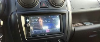
Installing a car radio is a creative process, but not very complicated. An experienced car enthusiast, at least a little familiar with the basics of electrical engineering, will be able to connect the car radio with his own hands without any problems. We will tell you in this article how to properly connect a radio in a car, and in what order this should be done.
It should be remembered that an incorrectly installed and connected radio will not only sound bad, but may even lead to a short circuit or even a fire in the car.
A good video instruction for installing and connecting a car radio in a car can be seen in the video at the bottom of this page.
Incorrect connection of the car radio causes the following problems:
- When parked, the radio consumes too much electricity, as a result of which the battery is constantly discharged and if parked for a long time, there is a chance that the engine will not start.
- When listening to music at high volumes, the radio starts to “stutter” and significant distortion of the sound signal appears. Also, at high volumes, the car radio may simply turn off.
- When you turn off the power, the radio settings are lost.
All of these problems in 90% of cases arise due to incorrect connection.
Classification of car radios by size
Car head units on the market differ in functionality, sound parameters and installation dimensions.
Developed by German manufacturers, the standard for car head units DIN 75490 was adopted in 1984 as international ISO 7736. It defined the standard mounting hole size for a car radio (1-DIN) as 180 x 50 mm. This size is the 1 DIN size. DIN stands for Deutsches Institut fur Normung - German Institute for Standardization. The abbreviation DIN stands for German standard.
Igor Syroedov
https://steer.ru/node/29859
Unification of installation dimensions expands the possibilities of using various radios in cars of different manufacturers and models. Currently, all radios are produced in accordance with the requirements of the international standard ISO 7736, but motorists prefer to refer to the similar international German standard DIN 75490.
All radios are produced in accordance with the requirements of the international standard ISO 7736, similar to the German DIN 75490
Usually there is enough free space behind the car console, so the standard regulates only the width and height of the radio, without limiting the depth. There are two formats: 1 DIN (178 x 50 mm) and 2 DIN (178 x 100 mm).
There are two radio size formats: 1 DIN (178 x 50 mm) and 2 DIN (178 x 100 mm)
In practice, the seat may be slightly wider and higher. In this case, to mask the cracks, decorative transition frames are used, which can be found on sale for almost any car model.
Decorative transition frames are used to mask the gaps between the radio and the seat
Adapter frames are also used when it is necessary to install a 1 DIN radio in a 2 DIN slot. The reverse procedure - installing a 100 mm high radio in a 50 mm opening - is impossible without significant modification of the console.
Video: choosing a radio by size
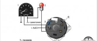
Installation method using alarm
Using two five-pin relays and several diodes, you can configure the operation of the radio using an alarm. The sound system is blocked automatically after the alarm is turned on - the power to the radio is turned off.
For the correct operation of such a circuit, it is necessary to familiarize yourself with the wiring diagram in the car and a detailed illustration of the operating principle of the device and the security system.
Power monitoring using an alarm helps prevent battery current leakage during long-term parking. Such control leaves only memory power in working condition.
Wire markings and topography of ISO connectors
Modern head units, as a rule, are equipped with connectors made according to the ISO 10487 standard. However, you can still find both radios and cars in which manufacturers use connectors of the original design. In such cases, the radios are connected via adapters.
ISO adapters are used to connect standard radios to original connectors.
The ISO standard defines the physical dimensions of three pads:
- block A black - power supply and control of the device;
- brown block B - connection of acoustics;
- block C is an optional section for connecting additional devices: navigator, additional amplifier, etc.
The ISO standard defines the physical dimensions of radio connectors
Despite the fact that the standard does not establish the purpose of the contacts, many manufacturers adhere to the same color marking of wires and topography (pinout, wiring) of connectors.
Radio began to sound in cars from the beginning of the 20s of the last century. At that time, there were two ways to improve a car: install a truck engine in a passenger car or install a radio in a car. The difficulty of improvement was equal. Car radios did not exist then, so the problem was solved as best they could. Home radios were converted to fit the 6-volt on-board network of the car, or simply ran on batteries. No one thought about sound quality. The home radio in the car did not last long. The constant shaking did its job, gradually destroying the electric lamps. A huge antenna was located under the ceiling, turning the car into a cage.
Igor Syroedov
https://steer.ru/node/29859
Table: pin assignments and color coding of wires of a standard ISO connector
| Section (block) | Contact number | Possible designation | Wire color | Purpose |
| A | 4 |
| Yellow | Radio power supply +12 V (main) |
| 6 |
| Blue | +12 V output to antenna amplifier | |
| 7 |
| Red | Radio power supply +12 V (control via ignition key) | |
| 8 |
| Black | Frame | |
| IN | 1 | RR+ | Violet | Right rear speaker (+) |
| 2 | RR– | Purple-black | Right rear speaker (–) | |
| 3 | FR+, RF+ | Grey | Right front speaker (+) | |
| 4 | FR–, RF– | Gray-black | Right front speaker (–) | |
| 5 | FL+, LF+ | White | Left front speaker (+) | |
| 6 | FL–, LF– | White black | Left front speaker (–) | |
| 7 | LR+, RL+ | Green | Left rear speaker (+) | |
| 8 | LR–, RL– | Green-black | Left rear speaker (–) |
The information given in the table is not exhaustive and completely reliable. You should check the markings of the wires and the purpose of the connector contacts in the documentation before connecting the radio.
Video: topography and disassembly of the ISO connector
General requirements and characteristics for the power source
To power the car radio, the power source must provide a constant voltage of + 12 volts. The requirements for the accuracy of maintaining voltage are not very high - the device will work even at a slightly lower level (although the volume may decrease), the radio will not fail even with a slight excess of 1..3 volts. The main thing is that the voltage is well filtered and, preferably, stabilized. Otherwise, rumble and hum will be heard .
There are also requirements for its load capacity of the power source. A medium power radio in medium volume mode consumes 2..4 amperes . If an increased sound level is required, you need to count on 10..12 amperes. For radios with display backlighting using incandescent lamps, you may need an additional reserve of another 0.5..1 ampere (this current is consumed even at zero volume). Based on these data, you can approximately calculate the required power of the power source.
Connecting the radio
When both the head unit and the car are equipped with standard ISO connectors with the same pinout, connection takes a matter of minutes. This is the simplest case. All work comes down to dismantling the old radio, connecting a new one to the same connectors and assembling the console.
Connecting a radio in the absence of a standard ISO connector
If there are no ISO connectors in the car or radio, then the best solution to the problem is to buy an adapter corresponding to the model of the head unit and the car and connect through it.
Video: ISO adapter
An alternative option is to cut off the standard cable and the cable that came with the new radio, and then connect all the wires in accordance with the connection diagram, making a homemade adapter.
When connecting in this way, special attention should be paid to the reliability of the contacts and insulation of the wires. They are connected using twisting, soldering and clamping clip connectors. It is better to insulate the places of twists with heat-shrink casing, discarding the adhesive tape.
Wires are connected using twisting, soldering and clip-on connectors
Connection without plug
In some cases, desperate experimenters try to connect a car radio without a plug, soldering wires to the connector pins. If you assemble the circuit without errors, then the radio will, of course, work. But the reliability of such a connection is very low.
At best, such experiments lead to periodic mutes. In the worst case, there may be a short circuit of the fallen power wire to the housing with unpredictable consequences.
In 1959, Blaupunkt-Werke released its millionth car radio - the best proof that radio had become truly accessible.
Igor Syroedov
https://steer.ru/node/29859
Alternative ways to connect power to the radio
In standard mode, the +12 V supply voltage is supplied to the radio via two wires. Red (signal circuits) is connected to the battery through the ignition switch. The presence or absence of voltage on it is determined by the position of the key.
The yellow wire constantly powers the radio's memory, where all settings are stored. Therefore, it is constantly connected to the positive terminal of the battery directly. When the battery is disconnected from the vehicle's on-board network, the individual settings of the head unit are lost. If there is control voltage at the signal input (red wire), +12 V from the yellow wire is supplied to all blocks of the device.
With a standard power connection, the yellow wire is connected to the battery directly, the red wire is connected through the ignition switch
Some vehicles have a lock position marked ACC. In this mode, the ignition is turned off, but power is supplied to individual devices, including the red wire of the radio.
If there is no ACC mode, the signal wire is connected together with the ignition. In this case, the radio will not be able to work autonomously.
The need for alternative power connection schemes arises when the owner wants to use the radio without turning on the ignition.
Connecting the radio to the battery, bypassing the ignition switch
Connecting the signal (red) power wire directly to the battery positive (in parallel with the yellow one) will ensure that the radio can be turned on at any time, regardless of the position of the key in the ignition switch. To minimize the consequences of short circuits, a separate fuse is included in the circuit.
To minimize the consequences of short circuits, additional fuses are included in the circuit
Connecting a radio via a button
It should be remembered that even when turned off, the radio consumes the energy necessary for memory operation. Current consumption may increase due to leakage if the red power signal wire is constantly connected to the battery, which negatively affects the battery charge level during prolonged periods of inactivity.
The simplest way to eliminate this drawback is to include a button or toggle switch in the circuit, which forcibly breaks the control circuit.
A button or toggle switch allows you to save battery energy when parked
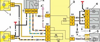
Automatic power off of the radio when the alarm is turned on
More complex ways to save energy when connecting a radio, bypassing the ignition switch, involve the use of relays that respond to the activation of the car's security alarm.
The relay that turns off the power supply to the radio is triggered by a command from the alarm unit
In the diagram above, the relay that turns off the power to the radio is triggered by a command coming from the alarm unit.
There are many other similar schemes. The choice of a particular option depends on the signaling capabilities.
Connecting the radio to the cigarette lighter
Connecting the radio to the cigarette lighter is a type of direct connection to the battery, bypassing the ignition switch.
When connected via a plug, the red and yellow wires are connected together. For long periods of parking, it is better to disconnect the plug from the cigarette lighter. This will save battery power, but will lead to loss of radio settings.
Turning on the head unit via a plug makes it difficult to use the cigarette lighter for its intended purpose. The disadvantage is eliminated by connecting the radio without a plug directly to the wires of the cigarette lighter socket.
The red and yellow wires are connected together to the cigarette lighter power contact
The red and yellow wires of the radio connected together are connected to the red wire of the cigarette lighter, which is supplied with +12 V from the battery. If the head unit is not protected by a built-in fuse, it will not hurt to install an additional one in the power circuit.
Some people are misled by the similar color coding of the radio and cigarette lighter wires. Without thinking, they are connected red to red, yellow to yellow. The radio will turn on anyway, but using the signal lights will disrupt normal operation.
The color markings of the cigarette lighter and radio wires do not match
The head unit consumes a current of about 10 A. A fuse of approximately 15 A is installed in the cigarette lighter circuit. You should check the current values and fuse ratings in the technical documentation before connecting the radio to the cigarette lighter. It is possible that the fuse will not withstand the additional load when the radio and cigarette lighter are turned on together.
Connecting the radio via diodes
Diodes are used when there is no ACC position in the lock so that the radio does not turn off along with the ignition.
The diagram for supplying power to the control input of the radio through diodes is shown in the figure. The yellow main power wire is connected, as usual, to the battery positive. Red (power supply for control circuits) - to the anodes (pluses) of two diodes. The cathode (minus) of one of them is supplied with power through the ignition switch. The cathode of the second is connected to the blue wire - the ANT+ contact of section A of the ISO connector - of the radio or (if available) to the REM signal output to turn on an additional amplifier.
Connecting the radio through diodes allows you to use the device when the car ignition is turned off
After turning on the ignition, +12 V is supplied to the ACC input via the red wire through the lock and the first diode. The radio turns on, voltage appears on the blue ANT+ wire and goes through the second diode to the ACC input.
Now the head unit will remain on even if the ignition is turned off. You can turn off the radio using the built-in controls. To turn it on again, you will need to turn the key in the ignition switch again.
Video: connecting a radio via diodes
Connecting a second (additional) radio
Two radios in a car are not a typical case. As a rule, if the owner is dissatisfied with the quality or capabilities, he changes the head unit to a new one. But when the standard radio does not just reproduce sound, but also performs other important functions for the car, it is difficult to find a full-fledged replacement.
Some owners prefer to solve the problem not by replacing, but by installing an additional device. In this case, it remains possible, for example, while playing music on the new radio, to use the on-board computer and listen to the radio using the old one.
When installing an additional radio, you have to solve two main problems: placing the second device in the cabin near the driver's seat and connecting the speakers independently.
Not all car models have free space in the console for additional devices. Therefore, for the sake of the second radio, they sacrifice low-value cavities: coin drawers, compartments and shelves that are in the area accessible to the driver’s hands. Often you have to adjust holes in plastic parts or cut new ones. Sometimes special podiums are arranged. Unfortunately, an extra device does not always fit organically into the interior of the cabin.
Gallery: examples of placing an additional radio in the car interior
Installed on the dashboard, the additional radio attracts attention
2 DIN seat allows you to place two 1 DIN radios
The radio in the glove compartment is invisible, but it is not very convenient to use
Sometimes to install an additional radio you have to cut out additional holes
If connecting the power to the second head unit is not fundamentally different from the case with one radio and usually does not cause any special problems, the acoustics require more attention.
Speakers cannot be connected in parallel to both devices at once. This significantly reduces the sound quality and can easily lead to malfunction of the final stages of the radio. Speaker systems must be connected one by one, that is, switch between outputs manually or automatically.
To implement this method in practice, various automotive relays are used. One of the possible schemes with manual control of switching acoustics using a button is shown in the figure.
To alternately connect acoustics to the outputs of two radios, use various car relays
Precautionary measures
You need to understand that incorrectly connecting the car radio can lead to unpleasant consequences:
- Breakdown of the radio;
- Deterioration in sound quality;
- Wiring short circuit;
- In rare cases, if you connect the radio to the battery incorrectly, you can quickly discharge it. Sometimes this can cause a fire.
In order not to waste your time, you can use the services of a car repair shop, but you need to be prepared to spend a certain amount that the service will charge for connection. In addition, it is worth considering that the cost of connecting a car radio to a foreign car (for example, Toyota) will be higher. The brand of the car radio is also taken into account. Thus, a Pioneer radio (which is the most common and beloved among motorists) will cost less than a Sony or Kenwood radio.
But if a car enthusiast has a desire to understand the device, the ability to spend a couple of hours and, no less important, the desire to save a decent amount of money, then the rest of the article will describe in detail how to connect a car radio according to the colors of the wires.
Tips for safe work
For long-term and high-quality operation of the audio system in a car, you need to know in detail the structure of the car's wiring and have basic skills in working with electronics. Some tips:
- set phasing before connecting speakers;
- lay wires, unscrew/tighten bolts, work with the tool slowly and carefully;
- do not allow wires to bend;
- upon completion of work, measure the current leakage with a multimeter
- use wires in accordance with the markings.
If you decide to do the installation yourself, it’s better to first see how others do it. There are many introductory videos online where experienced auto electricians demonstrate the technology with their own hands.
Today, almost every driver, while on the move, enjoys his favorite music. Car electronics manufacturers create all the conditions for a comfortable ride, and hundreds of specialists are finding new ways to make listening to music enjoyable and economical. By installing the radio yourself, you can learn a little more about your vehicle and expand the range of your skills.
Safety
Regardless of which car radio connection scheme you choose, you will have to pull at least one cable from the battery through the partition into the passenger compartment. A standard hole is sometimes provided for this purpose. In theory, the edges of this hole should be covered with a plastic or rubber bushing. Because even a non-sharp metal edge will wear out the insulation due to friction. We check the condition of the rubber or plastic and change it if necessary.
Standard hole edge protection
At the same time, inspect the other wires that are already lying here. Contact between exposed (damaged) wiring and the car body should not be allowed.
We stretch the wiring throughout the cabin so that the risk of damage is minimal. All areas where damage is possible (even theoretically) require additional protection. Use plastic or rubber pads, bushings, etc. Even 5–10 A is already serious.
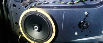
Do not connect the negative speaker terminal to the car body. Modern amplifiers in a tape recorder have a different design. By attaching a speaker in this way to save on wires, you can damage the amplifier.
What you will need
To connect you will need a set of materials:
- a piece of copper cable;
- soldering iron and lead-tin solder;
- insulating tape on a fabric or polyvinyl chloride basis, the use of heat-shrinkable tubing is allowed;
- a set of tools for removing the steering column casing;
- test device.
Plugs
ISO is an international standard established for car wiring and car radio production. The brown plug is responsible for connecting the acoustics, the black one is for powering it.
Standard radios produced for a specific car brand, as well as electrical wiring outputs for cars of various brands, have their own plug format, which will complicate installation a little. If the plug of the purchased speaker system does not match the socket, you should additionally purchase an adapter that will allow you to switch to the international standard. They exist for all car brands and are widely represented in the automotive market.
In some versions, adapters for other car brands may also be suitable. Installing an adapter designed for another car brand will not affect the quality or safety in any way. Many manufacturers provide their acoustic products with adapters for the ISO format. If the car's electrical wiring and plug comply with the ISO standard, then to connect you only need to connect them.