Despite the fact that in their meaning such concepts as the order of operation of the engine cylinders and their numbering are different. However, there is still a certain relationship between them. And every motorist should know the numbering of the cylinders. This gives him the opportunity to calmly operate in the order of their operation to carry out work on adjusting the thermal clearance of the valves and correctly connecting the wires to the spark plugs. Moreover, regardless of the operating manual, as well as the order of operation of the cylinders, the first serial number is always the master cylinder. There is always a candle in it.
How cylinders are installed in engines
There are many types of internal combustion engines - these include outdated engines with one or two cylinders, classic in-line options with four and six cylinders.
Larger structures had V-shaped blocks - these structures could contain eight or more combustion chambers.
What is the operating sequence of the KFX(TU3JP) cylinders?
or valve adjustment sequence?
I'll explain. Essentially. You said: “All inline fours have the same sequence.”
They proved to you that this is not so. Instead of admitting that you were wrong, you start talking all sorts of nonsense like “And you call this an engine?”
Re: Let me explain. > Essentially. You said: “All inline fours have the same sequence.” quoted1 > > they proved to you that this is not so. Instead of admitting that I was wrong,
Row arrangement
In this system, the cylinders are placed in one row. This configuration uses 2, 3, 4, five or 6-cylinder engines.
Internal combustion engines with two and three cylinders are installed on new cars quite rarely, despite the fact that the demand for them is gradually increasing.
If we talk about in-line “four”, then these blocks are installed in most engines for passenger cars - the volumes of these engines start from 1 liter, and the largest in-line internal combustion engine is 2.4 liters. and more.
What about now?
Contrary to popular belief, 8-cylinder engines are installed not only in luxury foreign cars, but also in ordinary tractors, trucks and construction equipment. As with weaker engines, the most balanced type is the in-line engine type. In other words, when all the cylinders are located in a row. They were used to equip the most expensive cars for a long time. This design was especially appreciated in America. However, the record holders here are the Germans, who highly value the balance and reliability of the in-line engine.
But even they, over time, had to switch to V-twin engines. The reason is simple and banal - the eight-cylinder Python simply did not fit in the standard engine compartment of modern cars.
In two rows
How to make a huge in-line internal combustion engine smaller?
- The engine can be "divided" in half, placing the two parts next to each other and having the pistons turn one crankshaft. This structure resembles the letter “V”.
- Here the combustion chambers are placed in two rows at an angle. This arrangement is quite common among manufacturers and is inferior only to the in-line “four”.
8 combustion chambers in this configuration are placed 4 in 2 rows. This is the most compact assembly for large-sized motors. If we talk about structures with 12 cylinders, the only difference is their number.
What is a V-twin engine?
With the increase in the number of cylinders in the engine, in-line designs became less convenient, and therefore they were replaced by a V-shaped layout. It involves installing cylinders with pistons in pairs, opposite each other and at an angle. The latter is called the camber angle and can vary from 10° to 120° between the axes. The number of cylinders in such units is from six to twelve, but this is always an even number. Many automakers, thanks to the V-shaped layout, were able to experiment with the number of cylinders, increasing their number to twenty-four, but such cars are not yet in mass production.
Depending on the camber angle, certain engine characteristics are achieved. So, for example, a small angle allows you to combine the advantages of both in-line and V-shaped engines in the engine.
V-engine
Among the advantages of V-shaped engines are:
- compact design;
- longer engine life;
- efficient and dynamic operation at various speeds.
- the design of such a unit is more complex, since it has two cylinder heads;
- high manufacturing cost;
- large vibrations during operation;
- difficulties with balancing.
With offset
The developers have found an alternative to make a powerful and at the same time small power mechanism for middle-class passenger cars. The offset design is a V-block with 6 cylinders.
They are located opposite each other diagonally. 6 cylinders tilted at fifteen degrees form a rather narrow and short structure.
Five-cylinder
These are units with 5 cylinders standing in a row. The relative displacement of the crankpins is 72 degrees. There are both two- and four-stroke samples; for the first (2 strokes), the standard order of optimal operation of the cylinder block for these engines is the activation sequence 1–2–4–3–5. This ensures uniform combustion of the fuel. These motors are widely used in marine technology.
On passenger cars, engineers report a different order for the operation of the “pots” of 5-cylinder typical engines - the 1-2-4-5-3 system.
Cylinder block:
Opposite type
It's no secret that on a V-like block the angle of inclination of the 2 parts is ninety or sixty degrees. If it is one hundred and eighty degrees, then it is a boxer engine.
Here the cylinders are placed opposite each other, in a horizontal order. The crankshaft in these devices is common, placed in the center, and the pistons move away from it.
Theory of internal combustion engine operation
The general principle of operation of engines running on gasoline or diesel fuel is known, perhaps, to everyone - fuel, burning in the cylinders, creates gas pressure that pushes the pistons, and then the force is converted into torque going to the wheels.
In order for the engine to operate evenly, fuel combustion does not occur in all cylinders at the same time, but in a certain order. The following are responsible for its compliance:
- gas distribution mechanism design;
- the angles between the cranks of the car crankshaft;
- cylinder arrangement - V-shaped or in-line;
- device of the ignition system for gasoline cars, and fuel injection pump for diesel cars.
Motors W
These power plants combine 2 rows of combustion chambers with a VR arrangement. In each row, the cylinders are tilted at an angle of fifteen degrees.
Both rows are installed at an angle of seventy-two degrees. If we are talking about a device with eight cylinders, the block consists of 2 V-like blocks located at a slope of seventy-two degrees.
Technical specifications
| GENERAL INFORMATION |
Cylinder arrangement and direction of rotation of the ignition distributor
Cylinder arrangement (belt side)
| Right side (back) | 1–3–5 |
| Left side (at the radiator) | 2–4–6 |
| Cylinder operating order | 1–2–3–4–5–6 |
Cylinder head
| 1 – left exhaust manifold; 2 – gasket; 3 – thermal protective screen of the exhaust manifold; 4 – gasket; 5 – right exhaust manifold; 6 – thermal protective screen of the exhaust manifold; 7 – cylinder head gasket; 8 – toothed belt casing; 9 – right cylinder head; 10 – camshaft that controls the intake valves; 11 – camshaft that controls the exhaust valves; 12 – washer; 13 – thrust ring; 14 – camshaft pulley; 15 – retaining ring; 16 – gasket; 17 – cylinder head cover; 18 – gaskets; 19 – intake manifold; 20 – idler pulley bracket; 21 – gasket; 22 – cooling system fitting; 23 – gasket; 24 – air intake bracket; 25 – EGR pipe; 26 – gaskets; 27 – EGR valve and vacuum modulator; 28 – vacuum pipes; 29 – air intake; 30 – gaskets; 31 – bypass pipe of the cooling system; | 32 – thermal protective screen of the bypass pipe; 33 – sealing washer; 34 – cylinder head cover; 35 – gasket; 36 – camshaft bearing cover; 37 – camshaft that controls the intake valves; 38 – camshaft that controls the exhaust valves; 39 – rear plate of the cylinder head; 40 – spark plug pipe laying; 41 – left cylinder head; 42 – left engine eye; 43 – cylinder head gasket; 44 – adjusting gasket; 45 – valve pusher; 46 – upper spring plate; 47 – spring; 48 – spring seat; 49 – valve guide; 50 – valve; 51 – exhaust bypass pipe; 52 – gasket; 53 – thermal protective screen of the exhaust manifold; 54 – camshaft sealing ring; 55 – crackers; 56 – sealing ring; 57 – thrust ring; 58 – gaskets |
Cylinder head
| Non-flatness: | |
| – 3VZ-FE engine (1992 and 1993): | |
| • cylinder head | 0.099 mm |
| • intake manifold | 0.099 mm |
| • an exhaust manifold | 1.0 mm |
| – engine 1MZ-FE (1994): | |
| • cylinder head | 0.099 mm |
| • intake manifold | 0.078 mm |
| • an exhaust manifold | 0.49 mm |
Camshaft
| Valve clearance (cold engine): | |
| – intake valves | 0.127 – 0.23 mm |
| – exhaust valves | 0.28 – 0.38 mm |
| Neck diameter | 26.940 – 26.960 mm |
| Bearing clearance: | |
| – nominal | 0.035 – 0.071 mm |
| – minimal | 0.099 mm |
| Jaw height: | |
| – 3VZ-FE engine (1992 and 1993) | |
| Camshaft controlling intake valves: | |
| – nominal | 42.158 – 42.260 mm |
| – maximum permissible | 42,000 mm |
| – 1MZ-FE engine (since 1994) | |
| Camshaft controlling intake valves: | |
| – nominal | 42.110 – 42.210 mm |
| – maximum permissible | 42.050 mm |
| Camshaft controlling intake valves: | |
| – nominal | 41.960 – 42.050 mm |
| – maximum permissible | 41.810 mm |
| Camshaft end play | |
| – nominal | |
| • 3VZ-FE engine (1992 and 1993) | 0.033 – 0.078 mm |
| • engine 1 MZ-FE (since 1994) | 0.040 – 0.088 mm |
| – maximum permissible | 0.119 mm |
| Camshaft gear play: | |
| – nominal | 0.02 – 0.20 mm |
| – maximum permissible | 0.47 mm |
| Distance between the ends of the camshaft gear spring | 22.5 – 22.9 mm |
Valve pusher
| Diameter | 30.96 – 30.97 mm |
| Pusher Channel Diameter | 31.00 – 31.018 mm |
| Pusher clearance in head: | |
| – nominal | 0.022 – 0.050 mm |
| – maximum permissible | 0.071 mm |
Oil pump
| Gap between outer rotor and housing: | |
| – nominal | 0.099 – 0.170 mm |
| – maximum permissible | 0.299 mm |
| Rotor axial play: | |
| – nominal | 0.030 – 0.088 mm |
| – maximum permissible | 0.149 mm |
Tightening torques
| Engine 3VZ-FE (1992 and 1993) | |
| Exhaust manifold nuts | 40 Nm |
| Crankshaft pulley bolt | 250 Nm |
| Idler pulley bolts: | |
| - number 1 | 35 Nm |
| - number 2 | 40 Nm |
| Toothed belt tension mechanism | 28 Nm |
| Camshaft pulley | 110 Nm |
| Cylinder head bolts: | |
| – stage 1 | 35 Nm |
| – stage 2 | turn to an angle of 90° |
| – stage 3 | turn to an angle of 90° |
| Oil pump bolts: | |
| – bolt head 12 mm | 35 Nm |
| – bolt head 14 mm | 40 Nm |
| Flywheel/drive plate | 85 Nm |
| Engine 1MZ-FE (since 1994) | |
| An exhaust manifold | 50 Nm |
| Crankshaft pulley bolt | 220 Nm |
| Idler pulley bolts: | |
| - number 1 | 35 Nm |
| - number 2 | 45 Nm |
| Toothed belt tension mechanism | 28 Nm |
| Camshaft pulley | 130 Nm |
| Cylinder head bolts: | |
| – stage 1 | 55 Nm |
| – stage 2 | turn to an angle of 90° |
| Flywheel/drive plate | 85 Nm |
Tactfulness of the motor
The operating principle of the cylinders consists of the following stages:
- Intake - the piston moves to the bottom dead limit, at the same time the combustion chamber is filled with air-fuel composition through the intake valve. The exhaust valve is closed.
- Compression - both valves are closed, the piston moves to the top dead limit, squeezing the fuel. The temperature in the chamber increases several times due to pressure and the pressure in the engine cylinder increases. For vehicles with a high octane rating, high octane fuel must be filled.
- The working stroke is when the valve is closed, and the liquid from the spark plug ignites. Under pressure in the cylinder of the unit when fuel is burned, the piston moves to the bottom, causing the crankshaft to rotate. For high productivity, it is necessary that the liquid is consumed in full before the piston reaches BDC. To ensure this process, the ignition timing is used. In new cars, the setting is performed by a built-in electronic unit. Older machines are equipped with a mechanical regulator.
- Exhaust - the working stroke ends with the evaporation of exhaust gases from the cylinders of the structure. At this stage, a significant process is taking place - cooling the system cylinders. It is performed with the intake and exhaust valves open at the same time. After the piston moves to TDC, the intake starts again.
Repair of car components
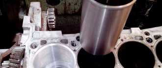
The cylinder block structure consists of parts that operate in aggressive conditions, and therefore are often subject to breakage and wear.
Restoring an engine cylinder block consists of the following operations:
| Power stroke | Fuel and air intake | Compression of the air-fuel mixture | |||
| Second | 180-360 | Fuel and air intake | Release | ||
| Compression of the air-fuel mixture | Working stroke | ||||
| Third | 360-540 | Compression of the air-fuel mixture | Fuel and air intake | Working stroke | Release |
| Fourth | 540-720 | Working stroke | Compression of the air-fuel mixture | Release | |
| Fuel and air intake | |||||
| No. of works | Operations Performed | Technical equipment. | |||
| 1 | Grinding the surface of the crankshaft bearing stop | Vertical milling machine | |||
| 2 | Replacing worn camshaft bushings | Press-fitting device | |||
| 3 | Repairing threaded holes | Drilled equipment, set of drills, lantern, die | |||
| 4 | Pressing out the fastening pins | Special press | |||
| 5 | Boring, repair of engine CPG cover. Adjustment by plane, installation by holes | Vertical milling machine | |||
| 6 | Processing the body for sleeves and boring for thrust edges | Vertical boring machine | |||
| 7 | Boring of main bearing seats | Horizontal boring machine | |||
| 8 | Gas-thermal spraying on treated bearing seats | Special technological equipment | |||
| 9 | Double-circuit boring of the body | Honing machine | |||
| 10 | Washing the engine and cleaning the oil channels | Equipment for jet washing of parts. | |||
| 11 | Painting the block | Spray gun. Compressor. |
Repair of the engine cylinder block ends with a control inspection on the test plate. Using a feeler gauge and indicator devices, the installation rigidity and alignment of the mounting components in the engine cylinder block are checked. After the engine cylinder body has been restored, a leak test is carried out.
Cylinder head assembly
Repair of the engine cylinder head is performed for the following reasons:
- broken drive shaft belt;
- cylinder head deformation due to overheating;
- duration of service lines;
- incorrect assembly after repair of the unit cylinder block.
Defects of engine cylinder head parts
You can restore defects using the following steps:
- grinding valves;
- the cylinder head is polished;
- gaskets and belts are being replaced;
- Bushings and valve seats are bored.
Post-repair control
After troubleshooting, the cylinder head is painted and the pressure in the cylinder is checked.
Numbering of cylinders of motors of various types
Such information is needed mainly for those who repair internal combustion engines of foreign cars. Typically, all front-wheel drive cars have a perpendicularly mounted motor.
In this situation, the cylinders of the structure are counted from one of the parts, and the main first cylinder is located from the passenger part.
- For V-shaped designs with multiple cylinders, the main cylinder is placed in the row closest to the passenger compartment on the driver's side. Then odd-numbered cylinders are placed, and multiple cylinders are placed from the radiator.
- In American buildings there are 2 variations of cylinder installation. Four or six-row American engines may have one main cylinder from the radiator, while the rest are counted towards the passenger compartment.
- Another variation with the opposite numbering, in this situation the main cylinder is the one located next to the passenger compartment.
Designers from France have also developed 2 ways to count the cylinders of the system. This is either a reading from the gearbox, or from the right side of the transmission, in V-like structures.
Therefore, given the huge amount of information, which is not always unambiguous, it is very important to read the instructions of the engine manufacturer - the vehicle. It would be a good idea to ask for help with this question from the community of car owners specifically for your car.
How does a W engine work?
W-shaped engine The fundamental difference between a W-shaped engine is the arrangement of cylinders with pistons in three or four rows, while they act on a common crankshaft. The camber angle is less than 90°. Some W-twin engine models feature a staggered cylinder arrangement, with each section having its own cylinder head. Such layout schemes are used not only in automobile engines, but also in aviation.
Just like a V-twin engine, such an engine can have up to twelve cylinders. However, its main advantage is its even more compact design. The main disadvantage of the W-shaped design is the need to manufacture a crankshaft of complex shape, as well as the use of a multi-level cooling system, which significantly increases the cost of engine production.
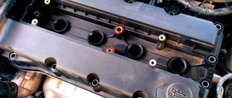
Photo of the location of the engine cylinders
I can't figure out where cylinder 1 is located
I can't figure out where cylinder 1 is located
Post by Valera93 » Jul 18, 2012, 12:54 pm
Re: I can’t figure out where cylinder 1 is located
Posted by redlife » Jul 18, 2012, 12:59 pm
Re: I can’t figure out where cylinder 1 is located
Post by SambaTDI » Jul 18, 2012, 01:13 pm
Re: I can’t figure out where cylinder 1 is located
Message t-3 » July 18, 2012, 14:46
Re: I can’t figure out where cylinder 1 is located
Post by Sanya » July 18, 2012, 2:56 pm
Re: I can’t figure out where cylinder 1 is located
Post by demyan » Jul 18, 2012, 6:34 pm
Re: I can’t figure out where cylinder 1 is located
Message by Bosun7779 » July 18, 2012, 19:02
Re: I can’t figure out where cylinder 1 is located
Post by Klip2 » Jul 18, 2012, 7:09 pm
Re: I can’t figure out where cylinder 1 is located
Post by Transporter T3 » Jul 18, 2012, 7:13 pm
Re: I can’t figure out where cylinder 1 is located
Post by Bosun7779 » July 18, 2012, 07:31 pm
Re: I can’t figure out where cylinder 1 is located
Post by puh » Jul 18, 2012, 9:24 pm
Re: I can’t figure out where cylinder 1 is located
Posted by redlife » Jul 18, 2012, 9:29 pm
Re: I can’t figure out where cylinder 1 is located
Post by Mikhail Cossack » July 18, 2012, 10:50 pm
Re: I can’t figure out where cylinder 1 is located
Post by Dimon » July 18, 2012, 11:13 pm
Re: I can’t figure out where cylinder 1 is located
Post by MAE$TR0 » Jul 18, 2012, 11:19 pm
Re: I can’t figure out where cylinder 1 is located
Post by kudrik » Jul 19, 2012, 03:06
Re: I can’t figure out where cylinder 1 is located
Posted by redlife » Jul 19, 2012, 03:08
Post by leo62 » 03 Apr 2016, 08:48
