Which fuse is responsible for the cigarette lighter of the VAZ 2104?
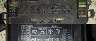
Fuse decoding table for VAZ / Lada 2104/2105/2107 (v. 2)
| Number | Rated current, A | Purpose of the fuse |
| 6 | 10 | Cigarette Lighter Clock |
| 7 | 20 | Sound signals Radiator cooling fan |
| 8 | 10 | Hazard warning lights Direction indicators (in hazard warning mode) |
| 9 | 7,5 | Rear fog lights |
New road markings in 2022
Attention! This article was published in the “Laws in Development” section. This means that the legislative changes discussed here may be adopted in the future. At present, the innovations discussed below have not entered into force, i.e. does not work.
Good afternoon, dear reader.
In this article we will talk about the new GOST 51256-2018 “Technical means of organizing road traffic. Road markings. Classification. Technical requirements”, which will replace the current GOST 51256-2011 starting from June 1, 2018 .
This document contains information about what road markings can be used on Russian roads.
Please note that this article was published in the “Laws in Development” section, despite the fact that the new GOST will come into effect in a few days. This is due to the fact that the main document for drivers is the rules of the road. Until the new markings are included in the traffic regulations, their use on the roads is meaningless, because Drivers will not be able to correctly interpret the meaning of the new lines.
However, it can be assumed that GOST was approved for a reason and changes to the rules will most likely be made in the near future. Therefore, let's look at the updated marking lines:
New road marking colors
5.1.1 For permanent horizontal markings (including duplicating the image of road signs), the following colors are established: white, yellow, red, blue, black, green. Temporary road markings are set to orange (except for markings 1.4,1.10,1.17.1.1.17.2, 1.26). The shape, dimensions, and color of the types of permanent horizontal markings are given in Table A.1 (Appendix A).
Currently, you can find permanent markings in the following colors on the roads:
- white;
- yellow;
- black (on vertical markings).
In addition, temporary orange road markings can be used.
The new GOST introduces the following additional colors:
- red;
- blue;
- green.
The blue markings will be discussed below. As for red and green colors, lines of such colors are not provided in the document. However, these colors can be used, for example, for color duplication of road signs on asphalt:
Blue markings at the intersection
The only marking line that can be blue is marking 1.7, indicating the boundaries of the lanes within the intersection:
At the same time, the new GOST provides for the possibility of using both blue and white versions of this line.
New yellow lines
Marking lines 1.3, 1.5, 1.6, 1.11 new GOST also allows for use in two color options (white and yellow):
The listed markings are used to divide the roadway into lanes (passing or oncoming).
The advantage is that yellow markings are better visible in the cold season, because... its color does not merge with the color of snow.
New marking option for pedestrian crossing
GOST 51256-2011 introduces new markings 1.14.3, which can be used to mark a pedestrian crossing:
It will be used along with the currently widespread 1.14.1 markup:
If you compare these marking lines, you can see that the middle of the traditional “zebra” was simply “thrown out”, leaving thin lines along the edges of the transition .
On the one hand, this will save paint when applying markings. On the other hand, thin lines are much less visible to the driver and this can negatively affect the safety of pedestrians. Also, thin lines will erase much faster than a full-fledged zebra stripe.
It is quite possible that such lines will be used at controlled intersections where traffic lights prohibit the movement of vehicles. That is, the crossing there is safe, and the markings will be used only to indicate the boundaries of movement.
Marking of traffic islands
Please note that the markings indicating boundaries . Let's figure out what this might be connected with.
Currently, the markings for the dividing island are a single element, and the rules do not prohibit running into or crossing such markings.
In the new version of GOST, marking 1.16 is only the inner part of the island. A 1.1 marking will be applied along the contour, which is prohibited from crossing. That is, the markings were updated in order to prohibit drivers from driving onto traffic islands.
New markings for public transport stops
Currently, in the traffic rules there is marking 1.17, which is used to indicate stopping places for route vehicles:
In addition to it, the new GOST introduces markup 1.17.2:
Please note that these markings are applied perpendicular to the edge of the roadway. The first line marks the beginning of the stop, and the second – its end.
The updated markings are shorter and require less paint to apply.
Unlike the traditional version, markup 1.17.2 has a slight drawback. If the driver sees a line in front of him, he cannot clearly say what is in front of him: the beginning or the end of the stop. This will cause serious difficulties if one of the lines is erased over time, but the other is not.
Markings for electric vehicles and “waffle iron”
Also included in the new GOST are marking lines 1.24.5 “Charging electric vehicles” and 1.26 “Waffle iron”:
Let me remind you that the listed lines are already included in the traffic rules. You can find detailed information about their use in the following articles:
In conclusion, I would like to remind you that the traffic rules contain a reference to GOST, in accordance with which the markings are numbered:
The marking numbering corresponds to GOST R 51256-2011.
However, this information is not currently updated, i.e. the rules refer to the previous document from 2011.
Let's summarize this article :
1. The updated GOST allows you to use paint of new colors (blue, red, green) for marking.
2. Marking line 1.7 can be painted in blue or white.
3. Lines 1.3, 1.5, 1.6, 1.11 can be painted in yellow or white.
4. New marking lines have been introduced for pedestrian crossings and public transport stops.
Please note again that this article discusses GOST 51256-2018, which is in effect from June 1, 2018 . However, in order for the innovations discussed today to appear on the roads, it is also necessary to update the traffic rules. This article will be updated as soon as changes to the rules are made.
Which fuse is responsible for reverse gear on a VAZ 2105?
Table: which fuse is responsible for what
| Fuse | Rated current, A | What protects |
| F1 | 10 | reverse lighting, electric heater, relay coil and rear window heating indicator |
| F2 | 10 | windshield washer motor, headlight washer motor and relay, windshield wiper relay |
| F3 | 10 | spare |
| F4 | 10 | spare |
THIS IS INTERESTING: What engine does the Nissan Almera have?
Yellow markings on the road - what they mean according to traffic rules
An increasing number of domestic drivers have begun to pay attention to the fact that unusual yellow markings have now appeared on the roads. And a logical question immediately arises about what it means according to traffic rules and what it is needed for. The article will talk about what yellow markings on the road mean and how they differ from orange ones.
CONTENT
What are the marking colors?
Several years ago, GOST came into effect, affecting the rules and procedure for applying markings in the Russian Federation. Some colors were added accordingly.
The white marking remained the main one.
Orange was approved as the color that designated temporary markings applied while road work was being carried out.
In addition, yellow and red have been added to these marking colors. Among other things, there are markings in blue, black and green.
True, the last three colors have not yet been included in the traffic rules, so they are unlikely to be seen on the road.
You need to know that yellow and orange markings are different things.
Such a variety of colors is necessary in order to increase the level of road safety. All the colors that were listed earlier are of the horizontal and vertical type.
Yellow markings on the road - why they are needed.
Yellow markings are used to prohibit certain actions. Its functions are the same as those of white markings were before. The only difference is that yellow markings are more visible, and this can increase the degree of overall road safety, because yellow markings are easier to see in bad weather or if snow has fallen.
Yellow markings can be of different types and used in different places. According to each of them, different points of the rules will apply.
Yellow markings - to improve visibility, instead of white.
Recently, GOST introduced such a clause that the markings, which previously were always white - permanent markings, can now be drawn in yellow. They say that it will be better visible in winter. Its meaning will be the same as that of the white marking. True, it has not yet been introduced into the traffic rules, and therefore we do not often see it on the road.
What kind of markup is this? Let's get to know her.
Double solid yellow markings
Double solid yellow markings are used to separate traffic flows. It is forbidden to cross!
Single solid yellow marking
This marking will be used instead of white marking 1.1 to separate traffic flows in opposite directions, and may mark the boundaries of traffic lanes in dangerous places on the roads; mark the boundaries of the roadway where entry is prohibited; marks the boundaries of vehicle parking spaces. It is forbidden to cross!
Single broken yellow marking
Marking 1.5 will be used to separate traffic flows in opposite directions on roads that have two lanes in both directions, to mark the boundaries of traffic lanes when there are two or more of them in one direction.
Marking 1.6 – yellow
The line where the strokes are longer than the spaces between them is called the approach line, will tell the driver that the intermittent line will soon end and there will be a solid marking line.
Double broken yellow markings.
A double broken yellow line is used in the same place as the white line to indicate the boundaries of reversible lanes.
Marking 1. 11 – yellow
- separates traffic flows of opposite or similar directions on sections of roads where changing lanes is allowed only from one lane;
- indicates places where it is necessary to allow movement only from the side of the broken line (at places of turn, entry and exit from the adjacent territory);
Yellow markings on the road - to prohibit stopping and parking
Yellow solid markings will be used to prohibit stopping on any section of the road.
This markup is numbered 1.4
This marking looks like an ordinary solid line and will be applied either to the curb stone or instead of markings separating the roadway from the side of the road.
This marking will prohibit STOPPING of vehicles.
“Stop” is a deliberate stop in the movement of a vehicle for up to 5 minutes, as well as for longer if this is necessary for boarding or disembarking passengers or loading or unloading the vehicle.
A yellow intermittent sign will be used to prohibit parking on a section of road.
In the picture above, it will be prohibited to park your vehicle in the PARKING PARK .
“Parking” is the intentional cessation of movement of a vehicle for a period of more than 5 minutes for reasons not related to the embarkation or disembarkation of passengers or the loading or unloading of the vehicle.
White and yellow pedestrian markings
To improve the visibility of a pedestrian crossing, the zebra can be painted white and yellow.
A pedestrian crossing can be marked without yellow stripes, but its purpose will not change - it is intended for pedestrians to cross the roadway.
The marking is a yellow zigzag on the road.
In addition, yellow markings can be applied in a zigzag or at an angle. This way the places where public transport stops are indicated. Ordinary drivers are not allowed to stop at these markings (unless they are loading or unloading a passenger, and even then without causing interference)
Waffle markings at an intersection
This is what they call markings that look like a waffle)
This markup will be used for clarity. If there are markings, the driver can clearly see the boundaries of the zone within which he cannot stop. This allows you to assess even before entering the intersection whether it will be possible to leave it without violating the requirements of the rules if a traffic jam has formed ahead along the route, which will force the driver to stop, creating an obstacle to the movement of vehicles.
It was specially invented so that there would be no disputes when recording an offense. I stopped at the markings, if I violated the camera, everything will be clearly recorded.
With this, we have discussed all the types of yellow markings that exist today. Not all of them can be found on the road, since some types are still in GOST, but they are not in the text of the traffic rules.
Start-stop button. A mounth later. Starter relay. — Lada 2107, 1.5 l., 1985 on DRIVE2
Today is exactly one month since I installed the Start-Stop button. There were no obvious glitches during this time, but the inquisitive mind again learned something new, but more on that at the end. And about a week later I redid the wiring to the starter. Let me remind you that my 2107 was produced in 1985. And in 1988, AvtoVAZ made a lot of changes regarding wiring and electrical equipment. Models from 1986 to 1988 became transitional; any of the wiring options could be installed on them. For example, I have an ST-221 starter installed.
Most 2107 after 1988 have the following starter connections
VAZ 2107 starter connection diagram: 1 – generator; 2 – battery; 3 – shunt coil of the stator winding; 4 – starter; 5 – serial stator winding coil; 6 – holding winding of the traction relay; 7 – pull-in winding of the traction relay; 8 – starter activation relay; 9 – mounting block; 10 – ignition switch
Historical background
Since 1986, VAZ-2107 vehicles have mainly used a 35.3708 starter with an end-mounted manifold.
Starter diagram for VAZ 2104, VAZ 2105, VAZ 2107. Until 1986, the ST-221 starter was used, which differs from starter 35.3701 in a cylindrical collector. Therefore, it has a different rear design. In addition, it has a different stator winding, consisting of two series and two shunt coils (the 35.3708 starter has one shunt and three series coils in the stator winding). According to its characteristics and installation dimensions, the ST-221 starter is completely interchangeable with starter 35.3708. Until 1985, additional relay 8 was not used in the starter switching circuit, and plug “50” of the starter was connected by a red wire through a mounting block to terminal “50” of the ignition switch for the Lada Classic. * For ST-221 starter. Actually, according to this scheme, my ST-221 is connected with a power wire without a relay through the ignition switch. And it didn’t give me peace.
VAZ 2107 starter connection diagram: 1 – generator; 2 – battery; 3 – shunt coil of the stator winding; 4 – starter; 5 – serial stator winding coil; 6 – holding winding of the traction relay; 7 – pull-in winding of the traction relay; 9 – mounting block; 10 – ignition switch
After I heard the retractor click several times, but the starter did not wake up, I decided to rejuvenate its connection circuit. And thereby remove the entire power load from sin away from the Start-Stop button from heaven. It’s better to clean the contacts or even replace the power relay for 25 UAH under the hood than to sit with a soldering iron and restore the micro-relay.
The second argument was 2104 fathers. The car is from 1991, German =). The relay is present (although it is not shown in the diagrams from “Behind the Wheel”). And it really starts with a kick.
No sooner said than done... Moreover, this is quite easy to do using only a mounting block and 6.3 mm terminals. According to the diagram, we need to take power +12 from the second pin of the black fuse block chip. It's next to the Thick Pink Wire. This pin for you will be empty, just like mine. We crimp the wire; it should be thick enough, like the red one that went to the starter. In my photo it's yellow
Additionally, in my situation, we install the relay on the wing.
The relay connection diagram is as follows: 86 - red, which used to go to the starter, 85 - black ground (I had blue) 87 - Our power wire that we just inserted into the power supply (yellow in my case) 30 - Red wire that goes to the starter .
By the way, you, like me, have this wire in the area of your pants. So feel free to turn it off. You immediately plug the mother into contact 86 of our relay, and cut off the father, which is on the starter side, press it onto the mother and connect it to contact 30 of the relay.
That's the whole change. I won’t say that my car didn’t start well before, but the way it starts now is definitely better. Those who subscribe to the channel have already seen the video “it’s getting cold :-(” even a cold car manages to start just by touching it. And this cannot but rejoice.
By the way, in diagrams 2106, 2101 the same situation occurs; the starter works through the ignition key.
VAZ 2106 starter connection diagram: 1 – starter; 2 – generator; 3 – battery; 4 – pull-in winding of the traction relay; 5 – ignition switch; 6 – holding winding of the traction relay
VAZ 2101 starter connection diagram: 1 – starter; 2 – holding winding of the traction relay; 3 – ignition switch; 4 – generator; 5 – mounting block; 6 – pull-in winding of the traction relay; 7 – battery
Of course it's up to you to decide. But I recommend redoing it even if AvtoVAZ decided to change it back in the late 80s 
Now about the button itself. Or rather about what was discovered. funny Especially for those who look at the R-fid tag as a security system =). If you remove the battery terminal, the security button will not turn off ;-). Since all this is controlled by a microcontroller (PIC16F628A), to deactivate the button, the microcontroller needs a signal from it using a 30 s timer. If you turned off the car and disconnected the ground, there will be no signal =), we arrived and disconnected the ground. They arrived 5 hours later, turned on the mass, started up, arrived, turned off the mass - there was no signal from the controller. And put the R-fid tag at home so as not to lose it, God forbid. If you have a mark like me, sleep peacefully. And whoever is thinking about a button, take a closer look at the cheaper version but with auto start.
P/S. Don't kick me too much =). It’s better when you know about it and can warn than to live in ignorance
Windshield wiper device
Before repairing faulty wipers, you need to understand their design features. The main components of wipers are:
- Electric motor.
- Electric washer pump.
- Circuit breakers.
- Control relay.
- The switch is a three-position switch that regulates the speed of the brushes.
- Brushes.
Actually, this is what cleaning the windshield from rain, dirt and dust in the summer is based on. If the wipers of the VAZ 2107 do not work, then the cause of the breakdown must be sought in one of the listed elements. What are the main types of malfunctions, we will consider further.
Possible windshield wiper malfunctions
The main types of malfunctions include the following reasons:
- the switch has failed, which happens in frequent cases;
- the fuse has blown, which could have happened as a result of an overload of the electric motor, water getting on it or overheating of the wiring;
- poor circuit contact or lack thereof;
- windshield wiper motor malfunction;
- breakdown of the VAZ 2107 windshield wiper relay.
If the breakdown consists of a blown fuse, then replacing it will not be enough; it is also necessary to find the true cause of such consequences. Next, we will consider the main types of wiper malfunctions on the VAZ-2107 with a detailed description of their solutions.
The wipers stopped turning on
If the wipers on a VAZ-2107 do not work in two switch positions, then the reason is most likely hidden in a blown fuse. This element is located on the fuse block and serves to protect the circuit from overloads and short circuits.
Checking the fuse is the first thing you need to start repairing. To check, you should use a tester, or simply exchange it for a known good one of the same rating. In rare cases, fuse contacts may oxidize and need to be cleaned and replaced.
Windshield wipers do not operate in intermittent mode
If a situation arises in which the wipers do not function in interrupt mode, then the breakdown should be looked for in the wiper relay. The cyclic operation of the products is ensured by closing and opening the contactor of the control relay. To check, we try to supply power to the relay block. In practice it looks like this:
- the relay is removed;
- use the switch located near the steering wheel to turn on the wiper switch;
- Using a tester, you need to check whether there is voltage at the terminal.
If there is no power, the switch needs to be replaced. The reason may be a break in the control circuit, so it is necessary to find and eliminate this defect. If there is power, but the relay does not operate, then it needs to be replaced. The relay cannot be repaired, so it only needs to be replaced.
The electric motor of the cleaner does not function
If the electric motor does not work, but there is voltage at its contacts, then the problem is in the device itself. This could be wear on the brushes or failure of the windings. The brushes wear out over time, and the winding fails when the motor is overloaded. These products can be repaired, but for this you need to contact a workshop.
The wipers do not reach the extreme point
Often, owners of domestically produced cars are faced with a problem when, when turning off the wipers, the blades stop at the point where they were, that is, they do not return to the lowest position. The problem with such incorrect stopping of the brushes is directly in the drive gearbox. The gearbox is equipped with a limit switch, which is activated by a cam. The cam is designed to control the position of the brushes after the power to the switch lever disappears.
A breakdown occurs mainly when the driver turns on the windshield wipers that are frozen to the glass. As a result, the gearbox fails and must be replaced with a new one.
Refinement of wipers
When it rains heavily, the seven's windshield wipers work perfectly (in constant mode). The disadvantage is the fact that during light rain (intermittent mode), the brushes can rub idle, wearing out and scratching the glass. This occurs due to a non-optimal pause between swings. This problem can be solved by modifying the wipers. We will find out further how to modify the wipers on the VAZ-2107.
Modification of the VAZ 2107 wipers consists of changing their operating frequency, or the possibility of its smooth adjustment.
- Initially, you need to remove the relay, which is located in the cabin, near the hood opening lever.
- It is necessary to remove the relay cover and replace the installed 62 kOhm resistor with another one whose resistance is 30 kOhm. This will reduce the wiper response interval from 4 seconds to 2 seconds.
- The resistor is soldered to the board on one side only.
- It is necessary to solder wires into the circuit break that will connect to a variable resistance from 100 to 500 kOhm.
- Once the wires are soldered, the relay can be assembled and installed in place.
- The device in the form of a variable resistor must be placed in a convenient place on the control panel, since it will be used to switch the operation of the brushes.
- This connection diagram allows you to select the optimal mode of operation of the windshield wipers in the range from 2 to 10 seconds.
After the circuit is assembled, you can turn on the wipers and check their functioning. The variable resistor looks like a regular regulator, which is shown in the photo below.
There is another simpler way to upgrade windshield wipers that does not require working with a soldering iron. Ready-made relays with pause adjustment are sold on the market. You just need to buy a similar relay and install it instead of the standard one. You can learn more about this in the video below.
Such a simple modification will significantly increase the service life of the brushes, which is also important for drivers. To summarize, it is important to note that repairing windshield wipers is not a difficult process, but in order to repair or find the cause of the breakdown, you must approach the situation wisely. Determine specifically how the wipers do not work, and only then look for the breakdown.
Where does which wire go, or just a diagram
Connecting wipers and washer
“Plus” power is supplied from the ignition switch through fuse No. 2 at 10 Amp of the mounting block. The permanent “plus” goes along the black and yellow wires to contacts “4” of the connectors of the gear motor and the steering column switch. It should not disappear even when the switch is in the “off” position. The blue wire supplies “+” 12 V power to the motor when the switch is in “continuous mode” position. On the blue-white wire, in the “off” position there should be a “minus”, and in the “continuous mode on” position the “minus” is turned off. This is done to slow down the motor when the power to the closer is turned off.
The red wire supplies the relay with “+” 12 V from the switch when the intermittent mode is turned on. At the moment of operation, contacts “2” and “4” close, and “1” and “3” open, the motor starts working and the brushes make one or two movements. Then “+” 12 V is turned off, and contacts “1” and “3” are closed to each other and to “minus”. The motor stops for a few seconds and then the cycle repeats.
The washer pump motor is connected to “+” 12 V constantly with a black and yellow wire through the same fuse No. 2. “Minus” is applied when you press the windshield wiper lever from bottom to top.
Video about how a windshield wiper works
Windshield washer does not function
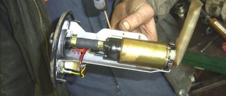
Since not only the detergent, but also washing is responsible for the cleanliness of the windshield, it is necessary to take into account the malfunctions of this device. The design of the mechanism consists of the following elements:
The washer reservoir is located in the engine compartment and is supported by a special bracket. It is filled with water or a special liquid for cleaning glass. The tank also has a pump through which the liquid is supplied through pipes to the nozzles, which spray it onto the surface of the glass.
Despite its simple design, the washer also sometimes fails, and there may be several reasons:
Electric motor malfunctions
Almost any malfunction that occurs with the windshield wiper motor leads to a malfunction of the mechanism as a whole. Main problems of the electric motor:
how to adjust wipers. Disassembly
If the motor is to be repaired, it will need to be disassembled.
This is done as follows:
Unscrew the transmission mounting cover and remove it.
Fuse burned out
Each electrical circuit of the VAZ 2106 is protected by a fuse that prevents overheating and spontaneous combustion of the wires. One of the most common reasons why the wipers do not work on this car. This is a blown fuse F2 installed in the fuse block. The latter is located on the driver's side near the hood release handle. On the “six”, this fuse protects the washer and wiper circuits, as well as the heater motor. The fuse is rated at 8 A.
If there is power at the connector:
- be sure to disconnect the positive terminal from the battery;
- inspect the connection to the electric drive (if any kinks or breaks are found on the wire, replace the wire);
- after inspecting the wiring, if no obvious damage is found, the windshield wiper motor needs to be replaced;
- disconnect the connector, unscrew the nut securing the trapezoid of the wiper mechanism to the electric drive gearbox;
- by pulling towards yourself, disconnect the spline connection;
- unscrew the bolts securing the drive and remove it from under the frame;
- install a new electric motor, repeating the procedure in reverse order;
Additional items
Under the hood
Additional headlight wiper fuses (2A rating) protect the motor windings. They are located on the supply wires next to the gearmotors.
p, blockquote 18,0,0,0,0 —>
p, blockquote 19,0,0,0,0 —>
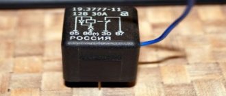
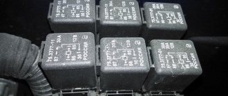
The starter activation relay 113.3747 or 90.3747-10 is located in the engine compartment on the right mudguard.
p, blockquote 20,0,0,0,0 —>
p, blockquote 21,0,0,1,0 —>
In the cabin
The windshield wiper relay (PC-514) is mounted under the panel on the left under the trim.
p, blockquote 22,0,0,0,0 —>
p, blockquote 23,0,0,0,0 —>
The ignition relay and the hazard warning and turn signal relays are installed on the front panel behind the instrument panel. The ignition relay (113.3747-10 or 90.3747-10) and the hazard warning and turn signal relays (23.3747 or 231.3747) have a bracket for direct mounting on the body.
p, blockquote 24,0,0,0,0 —>
p, blockquote 25,0,0,0,0 —>
The fog lamp fuse is located in the gear shift compartment, not far from the radio.
p, blockquote 26,0,0,0,0 —>
p, blockquote 27,0,0,0,0 —>
Scheme of VAZ-21043 and VAZ-21047 carburetor
1 — block headlights; 2 — side direction indicators; 3 - battery; 4 — starter activation relay; 5 — carburetor electro-pneumatic valve; 6 — carburetor microswitch; 7 - generator 37.3701; 8 — gearmotors for headlight cleaners*; 9 — electric motor of the engine cooling system fan; 10 — fan motor activation sensor; 11 — sound signals; 12 — ignition distributor; 13 — spark plugs; 14 — VAZ 21047 starter; 15 — coolant temperature indicator sensor; 16 — engine compartment lamp; 17 — low oil pressure indicator sensor; 18 — ignition coil; 19 — low brake fluid level indicator sensor; 20 — windshield wiper gearmotor; 21 — carburetor electro-pneumatic valve control unit; 22 — electric motor of the headlight washer pump*; 23 — electric motor of the windshield washer pump; 24 — reverse light switch; 25 — brake signal switch; 26 — hazard warning and direction indicator relay; 27 — windshield wiper relay; 28 — mounting block; 29 — lamp switches on the front door pillars; 30 — lamp switches on the rear door pillars; 31 — diode for checking the serviceability of the warning lamp for insufficient brake fluid level; 32 — lampshades; 33 — parking brake warning switch; 34 — indicator lamp for insufficient brake fluid level; 35 — signaling unit; 36 — plug socket for a portable lamp**; 37 — glove box lighting lamp; 38 — tailgate glass cleaner and washer switch; 39 — alarm switch; 40 — three-lever switch; 41 — ignition switch; 42 — ignition relay; 43—econometer; 44 — instrument cluster; 45 — carburetor air damper closed indicator switch; 46 — battery charge indicator lamp; 47 — indicator lamp for closing the carburetor air damper; 48 — indicator lamp for turning on the direction indicators; 49 — speedometer; 50 — fuel reserve indicator lamp; 51 — fuel level indicator; 52 — instrument lighting regulator; 53 — clock; 54 — cigarette lighter; 55 - fog light circuit fuse; 56 — heater fan electric motor; 57 — additional resistor of the heater electric motor; 58 — electric motor of the tailgate glass washer pump; 59 — rear fog light switch with on indicator; 60 — heater fan switch; 61 — switch for heating the glass of the tailgate with a switch-on indicator; 62-external lighting switch; 63 - voltmeter; 64-lamp indicator for turning on external lighting; 65-lamp for high beam headlights; 66 — low oil pressure indicator lamp; 67 — parking brake indicator lamp; 68 — tachometer; 69 — coolant temperature indicator; 70 — rear lights; 71 — pads for connecting to the heating element of the rear door glass; 72 — sensor for level indicator and fuel reserve; 73 — courtesy lamp for the rear part of the cabin; 74 — license plate lights; 75 — gear motor for tailgate glass cleaner.
How to replace the wiper relay
Most often, car owners have to replace the relay to eliminate a faulty wiper. How to replace the relay so that the wiper located on the windshield of the VAZ-2107 works again?
- Turn off the power.
- Unscrew 2 screws.
- If the plug is difficult to remove from the socket, you can remove it with a screwdriver.
All that remains is to install the new part and connect it.
Sources:
https://avtoladagood.ru/sovety-dlya-avtomobilistov/5489-gde-nahoditsya-rele-dvornikov-na-vaz-2105-foto.html https://avtoladagood.ru/sovety-dlya-avtomobilistov/5489-gde -nahoditsya-rele-dvornikov-na-vaz-2105-foto.html https://bumper.guru/klassicheskie-modeli-vaz/stekla/rele-dvornikov-vaz-2106.html https://kalina-2.ru /remont-vaz/rele-dvornikov-vaz-2105-gde-nahoditsja-foto
How does the wiper relay work?
The windshield wipers installed on the windshield of the VAZ-2107 function due to the coordinated operation of the motor, relay, fuse, switch and 12 V power source. Finally, short circuit contacts located at the bottom and top.
What happens next:
The operation diagram of the windshield wiper relay in the VAZ-2107 is as follows:
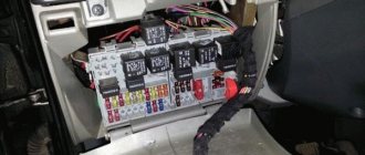
Additional block
It is installed in injection models under the glove compartment in the car.
p, blockquote 14,1,0,0,0 —>
Scheme
p, blockquote 15,0,0,0,0 —>
p, blockquote 16,0,0,0,0 —>
Purpose
p, blockquote 17,0,0,0,0 —>
- 15A Main Relay Fuse
- Main relay
- 15A Injection system power supply fuse (non-switchable voltage input)
- 15A Fuse for electric fuel pump relay
- Electric fuel pump relay
- Cooling system electric fan relay
Common faults and solutions
The reasons why wipers do not work on cars, regardless of whether it is a UAZ or a S7, are basically the same. Below are the malfunctions and methods for eliminating them.
| Malfunction | Remedy |
| The wipers do not work in both modes. | In this case, you should check the fuses. If they are burnt out, they need to be replaced with new ones. If only the contacts have oxidized, you need to pull out the fuses several times and put them in place. It may be necessary to replace the VAZ wiper trapezoid. |
| Brushes do not work only in intermittent mode. | In this case, you first need to check the power supply. If there is voltage, then the cause of the breakdown is in the relay. |
| The wiper switch is faulty | Change three lever switch |
| The wipers work, but when turned off they remain in an arbitrary position. The reason may be a breakdown of the gearbox, since it contains a limit switch. | It is necessary to clean the contacts or bend the switch plate. If necessary, the gearbox should be replaced. |
| The electric motor does not work. | In this case, you need to dismantle the electric motor and check the condition of the windings and brushes. |
| The brushes do not move when the gearbox is running. | The gear teeth are broken and need to be replaced. The crank may be loosely secured to the gear; you need to tighten the fastening nut. |