Part 1. Introduction
Flushing the fuel system, which will be the subject of today’s post, is not the first in the history of the car. Her first procedure was performed more than two years ago, in April 2013. Then the operation was carried out at a service station, respectively, using specialized equipment. The chemical used was a liquid from Liqui Moly, namely Benzin-System-Reiniger. The advantages of chemistry, in comparison with the popular Wynn's, included a much more careful attitude towards rubber products, as well as the absence of the need to change the oil after flushing the system.
Recently the moment came when I decided to delve into this topic again. This time I wanted to do everything myself, without the help of people with equipment. Doing everything yourself next to your own garage is much more pleasant for many reasons.
I was also extremely curious to see what the result would be after cleaning the fuel, taking into account that there was not a single refueling without the use of the Castrol TBE additive. In other words, this can indirectly confirm or refute the advisability of using an additive or flushing the fuel in cars that, from birth, or after extreme cleaning of the fuel, have been running on fuel with the addition of this additive.
Part 2. Preparation
Thanks to the many entries on this topic, the list of necessary elements for assembling the device is extremely clear: • VAZ fuel hose • Fine fuel filter for carburetor modifications of the VAZ • 2x Valve for tubeless passenger wheels • 4x Clamp • Plastic bottle, volume of at least 1 liter
This list should include a compressor with a pressure gauge, without which nothing will work. The volume of the bottle depends solely on human comfort - the larger the container, the less often you will have to pay attention to the pressure gauge and compressor to maintain pressure in the container. I took 6 clamps in case of unforeseen circumstances.
If with the equipment everything is extremely clear, then with the chemistry that will be such a delicate operation, everything is not so clear: I would not trust the ordinary “Solvent”, Wynn’s is also dismissed because of its aggressive effect, which is not denied by anyone and has been confirmed by many , as it turned out during the study of this topic. I would like to find and purchase chemicals from Liqui Moly similar to those used previously, but I was unable to do so - no matter where I asked, they were not available anywhere. To be fair, I note that I looked only in my city and only in those stores that have at least some trust.
In one of the establishments I was offered two options as an alternative - the same Wynn's and the product of the Russian company LAVR, namely LAVR ML-101. Previously, I had heard good reviews about products from the latter manufacturer, but I had never personally encountered or delved into the search for negativity, especially for this particular product. Next, the Internet, Drive2 and studying the results of a search query for LAVR ML-101. And to my surprise, I didn’t find any negativity; on the contrary, they talked about the advantages in the form of careful handling of rubber products, no need to change oil and spark plugs, as well as convincing efficiency. Seeing no alternative, I chose the option from LAVR.
As a result, the following set was drawn:
Part 3. Assembly
Perhaps I’ll start the description of the assembly by dividing the fuel hose in two. A fuel filter is inserted into the resulting gap and secured with clamps. Next, a hole is made in the lid of the selected container, into which a valve is inserted with force, from which the nipple was previously removed. Part with a thread, the valve is inserted into the fuel hose and secured with a clamp - you should pay attention to the position of the fuel filter so that the arrow on it points in the direction from the valve. A similar hole is made in the bottom of the bottle, into which a valve is also inserted, but with a nipple.
At this stage, the preliminary assembly can be considered complete.
Part 4. Process
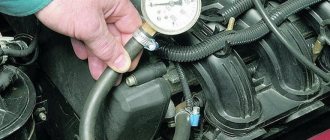
First, before starting to work on the car, you should turn off the fuel pump so that you don’t have to watch a fountain of 98-grade gasoline gush in the engine compartment at a pressure of 380–400 kPa (3.8–4.0 kgf/cm2). This can be done in two ways: • Raise the back seat, open the hatch to access the fuel pump and remove the chip. • Unscrew one screw at the front passenger’s feet, remove the plastic element and, just below the ECU, remove the 15A fuel pump fuse - this is the option I chose.
Holding the nut on the fuel hose with a wrench, that is, the one that is closer to the left side of the car, we turn the nut adjacent to the fuel pipe and the ramp, that is, the one that is closer to the engine. The nut on the hose is static relative to the hose itself, so there is no need to twist it.
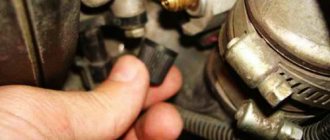
Having successfully released the connection, carefully remove the small rubber ring-seal from the tube and put it aside so as not to lose it.
Part 5. Description of the behavior of the car during washing
When first started using flushing chemicals, the car engine started up absolutely calmly, without any deviations. Throughout the first 15 minutes there were no changes, the speed remained as usual stable, the exhaust was also unremarkable.
When starting up, after 15 minutes of inactivity, the car started up a little less willingly, if only because I poured in an additional amount of chemical by briefly turning on the injectors. Although it is worth noting that the launch was successful the first time, after the first or second revolution of the crankshaft. For the first couple of seconds, the revs were below normal levels, and the exhaust had a blue tint and an unpleasant, pungent odor. Then the speed leveled off, but the exhaust remained unusual, slowly returning to normal with each new increase in speed.
At the end of the washing, the first start on gasoline differed from the usual only in a new portion of bluish acrid smoke. It seemed to me that its volume was even greater than when starting up for washing after a 15-minute downtime. After several presses of the gas pedal, the exhaust returned to normal.
Part 6. Impressions
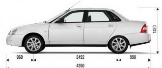
In addition to the Priora, the fuel system of the Ford Focus II 1.6L 115HP was simultaneously flushed, which is described in the full version of the entry on the BZ pages. Both cars are operated on AI98 with the addition of Castrol TBE additive. The Focus ran for at least 10tkm on this mixture; the fuel had not been flushed before. Priora also uses AI98 with the addition of the Castrol TBE additive; the additive began to be used even before cleaning the fuel, which was carried out 50 tkm ago, and there was not a single refueling without it, and therefore I think it is possible to judge its effectiveness based on the results of the work performed. Also, both cars run on iridium spark plugs, Priora on Denso iQ20, Focus on NGK, the model of which I no longer remember.
Signs of product wear
The first and main sign indicating possible malfunctions is the obvious smell of gasoline in the car interior.
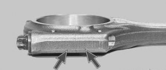
If there is no smell, you should pay attention to the appearance of the hose itself and its condition. Bend the product in different directions, there should be no cracks or holes
If there is damage (even minor), the hose must be replaced. In addition, there are often situations where the cause of fuel leaks is the connection between the hose itself, for example, with a metal tube of the fuel rail or a connecting tube coming from under the bottom of the car.
Malfunction of the adsorber and adsorber valve on a Priora: main symptoms
The fundamental element of the entire system is the solenoid valve, which is controlled by the ECU. It is because of the failure of this element that problems arise on the car. However, let’s look at the main signs of a malfunction of the gasoline vapor recovery system:
- Floating speed. Naturally, there is no need to rush to diagnose the system, since this phenomenon is often associated with a number of other problems, but it should not be ruled out either. Why do the revs fluctuate? The cause is a solenoid valve that may be stuck open. As a result, it turns out that air is sucked into the throttle assembly when starting the engine, which ultimately leads to the appearance of the effect of changing crankshaft speeds. Prior owners often encounter this problem, so it is important to pay attention to the serviceability of the solenoid valve. You will find out where it is located on Priora and how to check it in the sections below.
- The engine does not gain full power, which is quite understandable; an element of the fuel vapor recovery system is faulty. As a rule, this can be caused by clogged adsorber, which reduces throughput.
- The engine stalls at idle when trying to add gas.
- Fuel indication sensor readings are incorrect. It shows either a full tank or an empty one. This usually happens when the pressure relief valve does not cope with its function. The possibility of failure of the gas tank cap, which has a built-in breather, cannot be ruled out.
- Increased fuel consumption.
- When you unscrew the cap from the neck of the tank, a long hissing sound occurs, indicating that the pressure valve is not coping with the task (the pressure is not equalized). If hissing does not occur at all when unscrewing the lid, then this may also be a sign of a malfunction of the breather in the lid, since depressurization of the product is appropriate.
These signs indicate that there is a malfunction in the gasoline vapor recovery system on the Priora. In addition, if the solenoid valve (purge) fails, the Check Engine may light up on the instrument panel, and the corresponding error codes will be displayed on the on-board computer:
- P0441 - incorrect air flow through the adsorber valve;
- P0442 - leak in the gasoline vapor recovery system;
- P0443 - malfunction of the valve circuit of the gasoline vapor recovery system;
- P0444 - break in the canister valve wire;
- P0445 - the control circuit for the canister purge valve closes to ground;
- P0446 - malfunction of the control circuit of the vapor valve for collecting gasoline vapors EVAP (Evaporative Emission Control System Vent Control Circuit Malfunction).
If one of the errors listed above is displayed on the BC, then you need to look for a malfunction in the gasoline vapor recovery system. Typically, this error can be associated with a failed solenoid valve, a clogged filter element, or a faulty pressure relief valve.
How to change it correctly?
Next, we will look at how to correctly replace the working fluid of the cooling system in a Lada Priora car with an electronic pedal or with air conditioning. You can change the refrigerant at a service station, but this task is quite simple and anyone can handle it on their own. For the best effect, it is necessary to flush the cooling system, we will discuss this below.
Preparation
Before you begin the process, prepare the following:
- fresh refrigerant in the required volume;
- seal for the drain cover if the old one is worn out;
- set of wrenches;
- clean rags;
- container for collecting used antifreeze.
The Lada Priora Repair and Maintenance channel provided a video that demonstrated the procedure for draining the working fluid from the cooling system.
Step-by-step instruction
How to replace antifreeze on a Priora:
- Drive the car into a garage with a pit; you will need a flat surface to perform the work. Wait until the engine cools down; the entire process is carried out cold.
- There should not be high pressure in the cooling system. To reset it, open the hood and unscrew the expansion tank cap. If the engine is hot, coolant may spray out of the hole, so use a rag when opening it.
- Dismantle the plastic protection of the power unit. To remove it you need to unscrew two fasteners on the sides. It is not necessary to dismantle the clamps, but removing them will make the task more convenient.
- If your car is equipped with a transmission with control cables, then it is necessary to dismantle the starter device. To do this, disconnect the negative terminal from the car battery. Press the fastening of the connector with the wiring and disconnect the plug from the output of the traction relay. Remove the protective cap from the nut securing the tip of the wire connected to the positive terminal of the battery. Using a 13mm wrench, unscrew the nut and remove the cable tip from the contact screw on the traction relay. Then use the same tool to unscrew the screws and dismantle the starter device. If the car's transmission is controlled by traction, then there is no need to dismantle the starter.
- Find the drain plug; it is located directly on the cylinder block. You need to place an old bucket or basin under it, into which the used refrigerant will be drained. Unscrew the cap and wait until the liquid comes out of the system. Also unscrew the protective valve under the radiator device; some of the substance will also flow out of it. When the draining is complete, you need to tighten both plugs. Don't forget to check the condition of the seal on the drain cap. If it is worn out or there are traces of defects, the ring must be replaced.
- Assess the condition of the refrigerant drained from the refrigeration system. If there are traces of deposits, wear products, or the liquid as a whole is very cloudy and viscous, it is recommended to flush all components. To do this, pour about 7.8 liters of distilled water into the system through the expansion tank. You can add vinegar or citric acid to it to remove dirt. The use of special cleaning agents is allowed. After filling, the engine starts, you can perform a test drive. Then the procedure for draining the refrigerant from the power unit is repeated. If the liquid is still dirty, then the washing is repeated until it comes out clear.
- Assess the condition of all pipes and lines of the cooling system. If there is damage or signs of leaks, the hoses must be replaced.
- The next step is to pour new refrigerant into the system. To prevent an air lock from appearing in the lines and eliminate air entering the system, it is recommended to slightly loosen the clamp of the pipe connected to the throttle assembly. The hose is then disconnected.
- The cooling system is filled with fresh antifreeze through the filler neck in the expansion tank. New refrigerant is poured in until it comes out of the pipe disconnected from the throttle. When this happens, the line is connected into place and the clamp is securely tightened. Then the refrigerant is added to the system to the required level.
- All previously dismantled components are reassembled in reverse order.
- The engine starts and the journey is carried out. Now you need to once again make sure that the fluid level is correct. Make sure there is no leakage from the drain hole.
Automotive gasoline vapor trap: adsorber and its purpose
You should immediately understand the question of what an adsorber is and why it is needed on a car. Initially, it is worth noting that the correct name of this device is an adsorber, that is, it is written with the letter “d,” although many call it an absorber, which is not entirely correct. The difference between an adsorber and an absorber is that the first one accumulates vapors (in this case, gasoline) and holds them, while the second one completely absorbs the substance (that is, with the impossibility of their subsequent release).
We will find out why cars use an adsorber and not an absorber after understanding the purpose of this device.
A gasoline vapor collector is a kind of filter that prevents direct contact of gasoline with the atmosphere, which reduces the level of pollution. Such devices were invented after the introduction of the Euro-2 environmental standard, which prohibits atmospheric pollution with gasoline vapors.
The main purpose of the device is to temporarily absorb the vapors that form in the gas tank and use them for selfish purposes, that is, not just suppress, but transport them to the engine, where they will be supplied to the cylinders for combustion along with the fuel assembly.
Returning to the name of the device, we can safely say that the Priora and other modern cars use an adsorber that only temporarily accumulates gasoline vapor (which occurs while the engine is not running). The use of absorbers would not allow vapors to be directed into the combustion chambers of the engine due to their complete absorption by the sorbent.
This is interesting! Activated carbon is used as a sorbent in automobile adsorbers.
Procedure for replacing the fuel pump VAZ 2110
To replace the fuel pump, you will first need to dismantle the failed device; for this it is recommended to use the algorithm of actions described below:
Taking into account the peculiarities of the location of the fuel pump in the VAZ 2110, you will first need to remove the upper surface of the engine. A large amount of dust and other dirt often accumulates on the cylinder block and the pump itself, so they need to be wiped with a damp cloth or a brush with soft bristles; you can use special means.
It is recommended to prepare several bolts with a diameter of 8 mm in advance. They will be used as plugs for the hoses, and during the process of dismantling the pump there will be no time to search for them, since fuel will immediately begin to flow out of the holes.
At the incoming and outgoing hoses, you need to loosen the side clamps that secure them. This can be done using a screwdriver or a wrench specially designed for such purposes. Immediately after loosening their position, it will be possible to remove the clamps from the fittings and dismantle the injector.
The cylinder block will also need to be removed, since the device is securely fixed to it. This is quite easy to do if you unscrew a few nuts using a 13mm wrench.
Immediately after removing the nuts, the position of the fuel pump will weaken and it can be removed
It is also worth paying attention to the gasket located between the pump and the spacer - it has an extremely short service life, so it is best to replace it along with the main device. The spacer is necessary to ensure reliable protection of the fuel pump from high temperatures; when replacing the device, it should be cleaned of accumulated dust and dirt
There is another gasket between the spacer and the cylinder block; it is also recommended to replace it due to rapid wear
The spacer is necessary to ensure reliable protection of the fuel pump from high temperatures; When replacing the device, it should be cleaned of accumulated dust and dirt. There is another gasket between the spacer and the cylinder block; it is also recommended to replace it due to rapid wear.
After removing the old fuel pump, you can proceed to installing a new device, for this you should use the instructions below:
- If the car has a mileage of 100,000 km or more, you will first need to check the minimum protrusion of the pusher - the location of the new fuel pump and the correct functioning of it will depend on it. Otherwise, there is an increased risk of a significant reduction in fuel injection, which can lead to diaphragm rupture. Changing the protrusions of the pusher usually does not cause difficulties; it is enough to simply select and install suitable gaskets that will be located between the spacer and the cylinder block.
- Once the correct minimum projection is set, you should start turning the crankshaft at a low speed. At this time, the spacer should be pressed tightly against the cylinders, which will make it possible to measure the indicator of the pusher protrusion. The value can be dynamic and fluctuate constantly, but only within 0.8–1.3 mm. The gasket is changed in cases where the pusher is outside the specified range: depending on whether the value is too small or too large, its thickness is also reduced or increased.
- At the final stage, all dismantled parts and devices are installed. This process is not difficult; to implement it, it is enough to use the previous instructions, repeating all the described steps in reverse order.
How does a car's gasoline vapor recovery system (adsorber) work?
The principle of its operation on Priora is identical to other brands of cars, so let’s look at the overall picture.
- Gasoline has the property of releasing vapors, which usually accumulate in the upper part of the filler neck of the tank. For this, a separator is used, with the help of which these vapors are condensed and returned in liquid form back to the tank.
- Some vapors do not condense in the separator, so an adsorber is provided for this. In it, vapors accumulate and are retained (this happens when the car engine is turned off).
- After starting the engine, reaching operating temperature, and only with the throttle valve open (this is very important), the solenoid valve opens. When it is triggered, for which the ECU is responsible, gasoline vapor is supplied from the adsorber to the throttle assembly. This process is called purging. Its duration is controlled by the ECU.
- The process occurs as follows: the adsorber has a channel connecting it to the environment. As soon as the solenoid valve opens, the engine sucks in air, which, together with gasoline vapor from the adsorber, enters the throttle assembly.
- From the throttle, these vapors, along with the air, enter the intake manifold, where they are mixed with a portion of gasoline released from the injectors and are sucked into the combustion chambers of the cylinders. As a result, they are burned, thereby increasing the efficiency of the internal combustion engine.
The operating principle of the system is quite simple and reliable, but malfunctions occur, which leads to problems with engine operation. What are the signs of a malfunction of the adsorber and its valve on a Priora, and how to determine the failure of parts of this system, we will consider further.
Replacing injectors on a Lada Priora car
Before we move on to describing the process of removing the injectors, you need to select everything you need for the job. Here is a list of tools and consumables:
- Phillips screwdriver;
- set of hex keys;
- set of open-end wrenches;
- pliers;
- wrench and set of socket heads;
- flat screwdriver.
Sequence of work
- The block to which the wires of the Priora injectors are connected is manually disconnected and removed.
The block with wires on the Priora fuel rail is removed manually
The mounting fuel rail on the Priora can only be unscrewed with a Phillips screwdriver
The Priora fuel fitting should be unscrewed with only two keys
The O-rings from the Priora ramp should be removed so as not to lose them
The Priora ventilation hose can only be removed after loosening the clamp
It is convenient to loosen the Priora brake hose clamp with pliers
The Priora intake pipeline is held on top by only two nuts
After unscrewing the fasteners, you can simply pull the Priora pipeline towards you
How to remove the gasoline vapor separator and gravity valve on a Priora: repair and replacement
Often Prior owners wonder what kind of structure this is, which is located in the left rear wheel arch liner. This device is mistakenly called an adsorber. In fact, this is a separator, which is designed to allow gasoline vapors to condense on its walls, after which the fuel is returned to the tank in liquid form.
One of the most common types of separator malfunction is a violation of the seal of the housing.
This can be determined visually by inspecting the part, as well as by detecting oil stains on the surface and the characteristic smell of gasoline. Damage usually occurs at the fitting through which gasoline flows back into the tank. The photo below shows what a leak in the Priora separator housing looks like. If the hose does not have a clamp, it is recommended to install one.
If the part fails (if the body is damaged, which usually happens when the car does not use locker wheel liners), it must be replaced. It is completely replaced along with the gravity valve and tubes. The removal and replacement process is performed as follows:
- Jack up the rear left side and remove the wheel. If there is a fender liner, it must be removed. If it is not there, it is recommended to install it, which will increase the service life of the car body parts and the separator.
- Disconnect the fuel drain pipe that comes from the separator from the gas tank by squeezing the quick-release connector clamp to do this.
- Use a screwdriver to pry up the tube holder and remove it.
- Unscrew the four nuts securing the fuel vapor supply pipes to the separator and gravity valve using a 10mm wrench.
- Above the brake hose of the left wheel there is a mount for the gravity valve tube. Unscrew the nut with a “10” wrench.
- Above the clamp that connects the pipe of the main and additional mufflers, there is another pipe fastening, which is also unscrewed with a key “10”.
- After this, you can unscrew the separator mount (2 nuts at “10”) and remove it from the car along with the bracket.
- The separator is removed along with the tubes and gravity valve. After this, you should check the condition of the tubes and body of the product. Replace the device with a similar one along with the tubes.
- To remove the separator without removing the tubes, then follow these steps: Disconnect the tube from the separator at the bottom (after loosening the clamp), through which vapor flows from the tank into the device, and gasoline back into the tank.
- Unscrew the two nuts securing the separator bracket, then lower the part down, gaining access to the gravity valve (top).
- Using a slotted screwdriver, pry up the flange of the gravity valve and remove it from its seat. It is important not to damage the O-ring.
- Next, you can remove the separator. If the gravity valve O-ring is damaged, it must be replaced. This is very important, since often, in the absence of visible damage to the separator, the cause of the smell of gasoline not only in the rear of the car, but also in the cabin, is a malfunction of the rubber seal (its damage).
- On Priors, such an o-ring is used from Chevrolet Niva cars. And if you are convinced that the part is damaged and cannot be repaired (if the ring cannot be glued), then we buy a new one. The sealing ring for the gravity valve on the Priora from the Chevrolet Niva has article number 2123-116485-10.
- If the separator is completely replaced, the gravity valve tube must also be removed. To do this, disconnect the connection of the tubes from the gravity valve to the adsorber.
When purchasing a new separator for Priora, you need to know its number 2170-0116400502. It is equipped with a gravity valve and connecting pipes, so there is no need to purchase anything separately.
This is interesting! Violation of the integrity of the separator housing or the sealing ring of the gravity valve causes not only the smell of gasoline, but also unstable engine operation, as air leaks will occur.
Technical characteristics of the VAZ 21126 1.6 16kl engine
| Type | in-line |
| Number of cylinders | 4 |
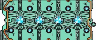
| Number of valves | 16 |
| Exact volume | 1597 cm³ |
| Cylinder diameter | 82 mm |
| Piston stroke | 75.6 mm |
| Supply system | injector |
| Power | 98 hp |
| Torque | 145 Nm |
| Compression ratio | 10.5 – 11 |
| Fuel type | AI-92 |
| Environmental standards | EURO 3/4 |
| Type | in-line |
| Number of cylinders | 4 |
| Number of valves | 16 |
| Exact volume | 1597 cm³ |
| Cylinder diameter | 82 mm |
| Piston stroke | 75.6 mm |
| Supply system | injector |
| Power | 114 – 118 hp |
| Torque | 150 – 154 Nm |
| Compression ratio | 11 |
| Fuel type | AI-92 |
| Environmental standards | EURO 4/5 |
| Type | in-line |
| Number of cylinders | 4 |
| Number of valves | 16 |
| Exact volume | 1597 cm³ |
| Cylinder diameter | 82 mm |
| Piston stroke | 75.6 mm |
| Supply system | injector |
| Power | 136 hp |
| Torque | 154 Nm |
| Compression ratio | 11 |
| Fuel type | AI-92 |
| Environmental standards | EURO 5 |
How to determine the status of the fuel pressure regulator (FPR)?
There are two ways to determine if an RTD is faulty:
- If the pressure with the engine not running with the fuel pump turned on is below 2.8 atm. To turn on the fuel pump directly without starting the engine, then on the diagnostic block we close the closest contacts to the gear shift lever.
- Turn off the fuel pump. The pressure in the ramp should drop by about 0.7 atm and remain at this level. If the pressure in the fuel system does not hold and immediately drops to zero, then the RTD or the pump check valve is faulty (located on the back side of the fuel pump motor; it is not advisable to change the pump because of it). Do not rule out cracks in the fuel line or poor condition of the injectors (gasoline flows in)
Where is the fuel pump located
The cover under which the fuel pump is located
The Priora fuel pump is located in the fuel tank. It is accessible under the rear seat of the car. When you remove the seat, you can find a hatch underneath it, which is secured with two screws. After unscrewing the screws and dismantling the cover, you can see the upper part of the fuel pump glass. The glass is attached to the tank with nuts through a metal ring and a rubber gasket, on 8 studs.
The fuel pump glass has:
- Fuel pressure control;
- Fuel pump;
- Fuel level sensor;
- Coarse fuel filter;
- Sump (bucket);
Review of the injector in the popular Lada Priora model
This device, popularly called an injector, is an electronic pressure fuel injection system. In fact, it was originally customary to call only injectors an injector.
The entire system includes many elements in its design, among which are the injectors themselves. Lada Priora is equipped with a distributed electronic injection system. Mixture formation occurs in the intake manifold of the car.
The Priora injector fuel supply system operates according to the following scheme: an electric fuel pump supplies fuel, a pressure regulator is responsible for maintaining pressure differences in the injectors and the intake manifold air.
The electronic ECU controller processes information from numerous sensors
: temperature sensor, engine detonation sensor, camshaft and crankshaft rotation sensor. Then the electronic module controls the ignition systems, regulates the fuel supply, and so on.
Information about air consumption, speed mode, throttle position and many other parameters is also taken into account. All changes in the operating parameters of the injector system change dynamically, based on the initial data received from the sensors.
The injection system on the Lada Priora is reliable and stable, but it is not without some drawbacks.
The main disadvantage can be considered contamination of the injectors due to the use of low-quality fuel, which leads to a deterioration in the dynamics of the car and disrupts the stability of the engine. There is a frequent need to wash the injectors or completely replace them.
The procedure for replacing injectors is quite simple, but the cost of the consumable part is relatively high for a budget car model.
Repair of the power system, instructions for repairing the fuel system of the Lada 2170, the procedure for assembling and disassembling elements of the power system of the Lada 2172, stages of removing and installing injectors on the Lada Priora car. Maintenance of the power supply system, cooling, lubrication, exhaust gases of the VAZ 2170 Priora engine, engine repair manual, cylinder heads of the VAZ 2172 Priora. Modifications of the VAZ 2171 Priora engine.
The power supply system includes elements of the following subsystems: Fuel supply system: 1 – fuel pipes (plastic); 2 – fuel filter; 3 – fuel filter mounting bracket; 4 – sealing ring of the fuel pump; 5 – fuel pump; 6 – spacer ring; 7 – pressure ring for fastening the fuel pump; 8 – filling pipe hose; 9 – plug of the fuel tank filler pipe; 10 – lining of the neck of the filling pipe; 11 – clamp; 12 – fuel tank filling pipe; 13 – air outlet hose; 14 – fuel tank mounting clamp; 15 – connector (quick connector); 16 – fuel tank; 17 – fuel pipes (metal); 18 – fuel supply hose; 19 – bracket; 20 – nozzles; 21 – fuel rail
– fuel supply system, including a fuel tank 16 Fuel rail and injectors: 1 – injector; 2 – fuel rail; 3 – sealing ring; 4 – nozzle clamp; 5 – fitting cap for monitoring fuel pressure
fuel pump 5 with built-in priora fuel pressure regulator, fuel pipes 1 and 17, hose 18, fuel rail 2 with injectors 1, as well as fuel filter 2; Air supply system: 1 – mass air flow sensor; 2 – sealing sleeve; 3 – air filter; 4 – throttle unit; 5 – intake manifold; 6 – idle speed regulator or additional air regulator; 7 – hose clamps; 8 – thermostat; 9 – supply pipe of the coolant pump; 10 – heating hoses for the throttle assembly; 11 – air supply sleeve; 12 – clamps for fastening the air supply hose
– an air supply system consisting of an air filter 3, an air supply hose 11, a throttle unit 4;
Lada Priora fuel vapor recovery system: 1 – front steam pipe; 2 – adsorber and purge valve tube; 3 – adapter; 4 – hoses; 5 – adsorber purge valve; 6 – clamp; 7 – fuel drain pipe; 8 – separator bracket; 9 – valve gasket; 10 – gravity valve; 11 – fuel vapor separator; 12 – rear steam pipe; 13 – middle steam pipe; 14 – steam pipe; 15 – adsorber
– a fuel vapor recovery system, including an adsorber 15, an adsorber purge valve 5, a fuel vapor separator 11, a gravity valve 10, connecting steam lines 1, 2, 12, 13, 14 and hoses 4. The functional purpose of the fuel supply system is to ensure the supply of the necessary amount of fuel into the engine in all operating modes. The VAZ 2172 engine is equipped with an electronic control system with distributed fuel injection. In the distributed fuel injection system, the functions of mixture formation and dosing of the air-fuel mixture into the engine cylinders are separated: the injectors carry out dosed injection of fuel into the intake pipe, and the amount of air required at each moment of engine operation is supplied by a system consisting of a throttle unit and an idle speed regulator. This control method makes it possible to ensure the optimal composition of the combustible mixture at each specific moment of engine operation, which allows you to obtain maximum power with the lowest possible fuel consumption and low exhaust gas toxicity. The fuel injection system and ignition system are controlled by an electronic engine control unit (ECU), which continuously monitors, using appropriate sensors, the amount of engine load, the speed of the vehicle, the thermal state of the engine, and the optimality of the combustion process in the cylinders of the Lada Priora engine. A feature of the injection system of the VAZ-2170 Lada Priora is the synchronization of injector operation in accordance with the valve timing (the engine control unit receives information from the phase sensor). The controller turns on the injectors sequentially, and not in pairs or simultaneously, as in asynchronous injection systems. Each injector is activated through 720° of crankshaft rotation. However, in the starting modes and in the dynamic operating modes of the Lada Priora engine, an asynchronous method of fuel supply is used without synchronization with the rotation of the crankshaft. The main sensor for the VAZ 2170 fuel injection system is the oxygen concentration sensor in the exhaust gases (lambda probe). It is installed in the engine exhaust manifold and, together with the engine control unit and injectors, forms a control circuit for the composition of the air-fuel mixture supplied to the engine. Based on sensor signals, the engine control unit determines the amount of unburned oxygen in the exhaust gases and accordingly evaluates the optimal composition of the air-fuel mixture entering the engine cylinders at each time. Having detected a deviation of the composition from the optimal 1:14 (fuel: air), which ensures the most efficient operation of the exhaust gas catalytic converter, the control unit changes the composition of the mixture using injectors. Since the oxygen concentration sensor is included in the feedback circuit of the engine control unit, the air-fuel mixture control loop is closed. A feature of the engine control system of the VAZ 2170 Lada Priora is the presence, in addition to the control sensor, of a second diagnostic oxygen concentration sensor installed at the outlet of the converter. Based on the composition of the gases passing through the neutralizer, it determines the efficiency of its operation.
The fuel tank 16 is welded, stamped, installed under the floor of the Lada Priora body in its rear part and secured with two steel clamps 14. To prevent fuel vapors from entering the atmosphere, the tank is connected through a fuel vapor separator 11 and a gravity valve 10 by steam lines 12, 13, 14 and 1 with adsorber 15. An electric module of an electric fuel pump (fuel pump) 5 is installed in the flange hole in the upper part of the tank, which combines the pump itself, a fuel level indicator sensor and a fuel pressure regulator. At the rear of the tank there is a pipe for connecting the filling pipe 12. From the pump, fuel is supplied to the fuel filter 2, installed below on the base of the body, and from there it enters the fuel rail 21, mounted on the engine cylinder head. From the fuel rail, fuel is injected by injectors 20 into the intake channels of the cylinder head, with the fuel jet directed towards the intake valve. Excess fuel is drained into the fuel tank through a fuel pressure regulator installed in the electric fuel pump module. This installation scheme for the fuel pressure regulator, in addition to eliminating the long return pipeline, helps prevent an increase in the temperature of the fuel in the tank, causing excessive vaporization.
Fuel pump (electric fuel pump module) 5 is submersible, vortex type, with a coarse fuel filter. The VAZ 2170 pump provides fuel supply and is installed in the fuel tank, which reduces the possibility of vapor locks forming, since fuel is supplied under pressure and not under vacuum. The fuel pump supplies fuel from the fuel tank through the main fuel filter into the VAZ 2171 injector rail at a pressure of more than 380 kPa.
Fine fuel filter 2 is full-flow, mounted in bracket 3 on the base of the body next to the fuel tank. The filter is non-separable, equipped with a steel housing with a paper filter element.
Fuel rail 21, which is a hollow tubular part, serves to supply fuel to the injectors and is mounted on the cylinder head. The engine uses a drainless power supply system; the pressure in the rail is maintained by a fuel pressure regulator installed in the Lada Priora electric fuel pump module. Nozzles 20 are attached to the ramp with clamps 4 through rubber O-rings. To equalize the pressure in the injectors, fuel is supplied to the middle part of the ramp.
The nozzles with their sprayers enter the holes located above the inlet channels of the cylinder head of the VAZ 2171. The nozzles in the holes are sealed with rubber O-rings. The injector is designed for dosed injection of fuel into the engine cylinders and is a high-precision electromechanical valve in which the shut-off valve needle is pressed to the seat by a spring. When an electrical impulse is applied from the control unit to the electromagnet winding, the needle rises and opens the nozzle hole, through which fuel is supplied to the intake pipe of the Priora engine. The amount of fuel injected by the injector depends on the duration of the electrical pulse.
The fuel pressure regulator is installed in the fuel pump module and is designed to maintain constant fuel pressure in the fuel rail. The regulator is connected to the beginning of the supply line immediately after the fuel filter and is a bypass valve with a spring having a strictly calibrated force.
Air filter 3 is installed in the front part of the engine compartment of the VAZ 2172 on three rubber supports. The filter element is paper, flat, with a large filter surface area. The filter is connected by a rubber corrugated air supply hose 11 to the throttle assembly 4. A mass air flow sensor 1 is installed between the hose and the filter (see “Electronic engine control system (ECM)”).
Throttle assembly 4 is mounted on the intake manifold 5. It meters the amount of air entering the intake pipe. The flow of air into the Prior's engine is controlled by a throttle valve connected to the accelerator pedal drive. The throttle assembly includes throttle position sensors 4 and an idle speed regulator 5. In the flow part of the throttle assembly (in front of the throttle valve and behind it) there are vacuum sampling holes necessary for the operation of the crankcase ventilation systems and the collection of fuel vapors.
Idle speed regulator 5 regulates the crankshaft rotation speed in idle mode, controlling the amount of air supplied bypassing the closed throttle valve. It consists of a two-pole stepper motor and a cone valve connected to it. The valve extends or retracts according to signals from the engine control unit. When the regulator needle is fully extended (which corresponds to 0 steps), the valve completely blocks the air passage. When the needle is pushed in, an air flow rate is provided that is proportional to the number of steps the needle moves away from the seat. By changing the amount of opening and closing of the regulator valve, the control unit compensates for a significant increase or decrease in the amount of supplied air caused by its suction through a leaky intake system or, conversely, by a clogged air filter.
The fuel vapor recovery system prevents the release of fuel vapors from the power system into the atmosphere, which adversely affect the environment.
The system uses the method of vapor absorption by carbon adsorber 15. It is installed in the engine compartment on the radiator trim panel and is connected by steam lines to a fuel vapor separator 11 installed in the niche of the left rear wheel, and to the adsorber purge valve 5 located in the engine compartment on the decorative engine casing . The solenoid valve for purge the adsorber switches the operating modes of the system based on signals from the engine control unit.
Fuel vapor from the tank is partially condensed in separator 11, the condensate is drained back into the tank through tube 7. The remaining vapor through the gravity valve 10 installed in the separator passes through steam lines 12, 13, 14, 1 and enters the adsorber 15. The second fitting of the adsorber is connected hose with valve 5 for purge of the adsorber, and the third - with the atmosphere. When the Lada Priora engine is turned off, the third fitting is closed by a built-in check valve; in this case, the adsorber does not communicate with the atmosphere. When the engine starts, the ECU begins to send control pulses to the solenoid valve. The electromagnetic valve opens; under the influence of vacuum, the check valve in the adsorber also opens, due to which air from the atmosphere and fuel vapor from the separator enter the adsorber. At this time, the sorbent is purged: gasoline vapors are discharged through hoses 4 and throttle assembly 4 (see Fig. 5.21) into the intake manifold 5. Malfunctions of the fuel vapor recovery system lead to instability of idle speed, engine shutdown, increased toxicity of exhaust gases and deterioration driving performance of the car.
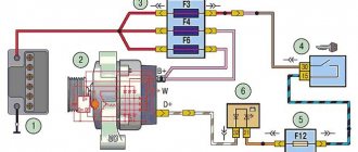
Location of Priora fuses under the hood
- F1 (30 A) – power supply fuse for the electronic engine control system (ECM);
- F2 (60 A) – fuse for the power supply circuit of the engine cooling system fan (power circuit), additional relay (ignition relay), rear window heating, electrical package controller;
- F3 (60 A) – fuse for the power supply circuit of the electric fan of the engine cooling system (relay control circuit), sound signal, alarm signal, ignition switch, instrument cluster, interior lighting, brake light, cigarette lighter;
- F4, F6 (60 A) – generator power circuit fuses;
- F5 (50 A) – fuse for the power supply circuit of the electromechanical power steering
Relay and fuse box for Halla air conditioner
- right electric fan power supply fuse (30 A);
- fuse for the power supply circuit of the left electric fan (30 A).
- right electric fan relay;
- additional relay (sequential activation of left and right electric fans);
- left electric fan relay;
- heater fan power supply fuse (40 A);
- compressor power supply fuse (15 A);
- heater fan relay;
- compressor relay.
Panasonic air conditioner relay and fuse box
- Heater fan maximum speed
- Right fan
- Fan sequential relay (low speed)
- Left fan
- Left fan fuse (low speed)
- Right fan
- Heater fan
- Compressor
- Heater fan
- Compressor
Important nuances
There are a few things to keep in mind when cleaning your injectors. Here they are:
You cannot save on flushing fluid. The injector is a very important part of the engine. And it is extremely sensitive to the quality of the flushing fluid. The optimal choice for cleaning Priora injectors is a product from Wynns, developed specifically for injection engines.
The cost of a liter bottle is 700 rubles;
You need to be very careful when removing an empty plastic bottle from the hood. It should be remembered: the pressure in it is enormous, so it can explode literally from one careless poke with a finger, and flying nipples can seriously injure the driver.
Replacing injectors is a long procedure. Nevertheless, it is quite within the power of a novice driver if he has at least a vague understanding of the structure of an injection engine. When cleaning the injectors, the situation is much simpler: you just need to be able to use a drill and know where the main fuel hose is located.
Cleaning Priora injectors
There are two options for washing injectors: with and without removing them from the car. The removed injectors are washed on special stands using ultrasound, under the influence of which even the oldest contaminants disappear. Ordinary drivers do not have such stands, so below we will consider a more popular option for washing injectors without removing them from the Priora. Here's what you'll need for this:
- liter of special flushing fluid;
- two automobile nipples;
- automobile fuel filter;
- a pair of metal clamps;
- a meter piece of rubber hose with a diameter of 12 mm;
- drill with 13 mm drill bit;
- electric pump;
- two liter plastic bottle.
Flushing sequence
- The bottom and cap are drilled into the plastic bottle. This is done with a “13” drill. Automotive nipples are inserted into the holes.
Ordinary car nipples are inserted into the holes of a plastic bottle
Priora injectors are washed using a filter and a plastic bottle
The green button is clearly visible on the Priora fuel hose
The main fuel hose of the Priora is connected to the fuel filter for flushing
The device for washing Priora injectors is assembled and ready for use
A car water pump plays an important role in the operation of a car engine. It is possible to recognize its malfunctions using the following article: https://vazweb.ru/desyatka/pitanie/zamena-forsunok-vaz-2114.html
Replacing injectors on a Lada Priora car
Before we move on to describing the process of removing the injectors, you need to select everything you need for the job. Here is a list of tools and consumables:
- Phillips screwdriver;
- set of hex keys;
- set of open-end wrenches;
- pliers;
- wrench and set of socket heads;
- flat screwdriver.
Sequence of work
- The block to which the wires of the Priora injectors are connected is manually disconnected and removed.
The block with wires on the Priora fuel rail is removed manually
The mounting fuel rail on the Priora can only be unscrewed with a Phillips screwdriver
The Priora fuel fitting should be unscrewed with only two keys
The O-rings from the Priora ramp should be removed so as not to lose them
The Priora ventilation hose can only be removed after loosening the clamp
It is convenient to loosen the Priora brake hose clamp with pliers
The Priora intake pipeline is held on top by only two nuts
After unscrewing the fasteners, you can simply pull the Priora pipeline towards you
Priora fuel pump fuse
The Priora fuel pump fuse is not located in the standard location for all fuses. It is located at the front passenger's feet, under the footwell air duct cover.
The red oval shows the fuel pump fuse
Rated current of this fuse = 15A, number F3;
It is strictly prohibited to install fuses with a rating higher than specified.
Mechanical fuel pump VAZ-2110 - characteristics and design
This type of mechanism is used exclusively on cars with carburetor engines. This VAZ-2110 fuel pump has its own mechanical drive from the camshaft, and it is located on the internal combustion engine.
By its design, this element is one of the types of piston and includes the following parts:
- Two-piece body with a lid on top.
- Diaphragm. It is installed between the lower and upper parts of the housing.
- Return spring.
- Stock. It is rigidly connected to the diaphragm.
- Discharge and suction valve. It is located at the top of the pump.
- Mechanical drive.
- Mesh filter.
The drive of this device, as we said earlier, is carried out from the camshaft eccentric. When this element rotates, the part moves the rod with the diaphragm down, and the spring force is overcome. The volume of space above it increases, and gasoline, due to the resulting vacuum, enters the pump through a separate valve from the gas tank. The discharge valve is closed.
The main operating mechanism of the pump is the diaphragm. It consists of two membranes, between each of which there is its own gasket. The diaphragm is connected to the rod. The latter interacts with the mechanical drive parts. There are different pump drive schemes. For example, domestic “tens” use a design that consists of a pusher and a lever with a balancer. Foreign cars use their own technology with a double-arm “rocker arm”.
https://arenda-pieter.ru/drugoe/shema-toplivnoj-sistemy-priora.html https://mazda22.ru/servis/toplivnaya-sistema-priora-inzhektor-17.html
Design and general diagram of the EVAP gasoline vapor recovery system
The design and operating principle of the device in question is quite simple. Below is a diagram.
To understand this, you need to know that the system consists of a number of the following parts:
- The separator is needed to capture gasoline vapors and then return it in liquid form back to the tank. On Priora it is located in the left rear wheel niche. It is important not to confuse it with an adsorber. The separator (top) has a built-in gravity valve.
- The gravity valve is needed to eliminate the possibility of fuel leaking from the tank if the vehicle rolls over in the event of an accident. It is also called a safety or safety valve, which is triggered when the vertical deviates by an angle of more than 90 degrees.
- The pressure relief valve is a device that eliminates the possibility of deformation of the metal tank when gasoline is used up. To put it simply, as fuel is consumed, a vacuum forms inside the sealed tank, which can cause deformation of its walls. To prevent this, a pressure sensor is used, which is also called a breather. With its help, the pressure inside the tank is equalized with atmospheric pressure. Its role is played by the atmospheric channel on the adsorber. When a vacuum is created in the tank, air is sucked in through the air channel, thereby equalizing the pressure in the tank. If the channel is faulty (contaminated), then the risk of tank deformation increases. That is why the Priora uses a gas tank cap with a valve for air intake as a safety net. This valve does not release air from the tank, but lets it in to stabilize the pressure.
- Absorbent - as mentioned above, it is activated carbon that temporarily absorbs and retains gasoline vapors that enter the engine during purging.
- The filter prevents the possibility of activated carbon granules entering the purge valve, as well as contaminants entering the adsorber through the air channel.
- Electromagnetic valve (canister purge valve)—its role in the system is key, since it is responsible for opening the channel for sucking gasoline vapors from the canister.
- Connecting tubes - needed to connect the adsorber to the gas tank, separator and other structural elements.
The operation of the system is controlled by an electronic control unit, so its malfunction is necessarily accompanied by the display of the corresponding error codes on the BC screen.
Are the valves bent?
Each engine in a Lada Priora car bends a valve, this also applies to the most powerful unit number 126 by 16. They will tell you this in any service center that services domestic cars. But novice drivers should know that the engine bends components for a reason, and if you follow the operating rules, you will not encounter this problem.
The Lada power plant bends parts only if the routine work to replace the belt and other components of the gas distribution mechanism (GRM) is violated. The motor bends the valve if the rollers, belt or water pump were not replaced in time. When one of these elements breaks, the number 126 pistons meet the valves. Due to this design feature, the motor bends the parts. The solution to the problem is a major overhaul of the Lada.
So, the task of the owner of a Lada Priora with engine number 126 for 16 cl is to check the timing belt in a timely manner.
The rollers and timing pump number 126 should also be given attention when inspecting the belt. After all, the engine bends parts even with faulty rollers
Sometimes the timing belt and its components wear out prematurely - you will know this by vibrations from the engine compartment and an unpleasant grinding noise. Engine number 126 bends the valve, so do not forget to change the timing components in time and repair this unit.
Injectors installed on Priora
The Lada Priora car is equipped with imported injectors manufactured by the German company BOSCH. These devices are highly reliable. Their service life can reach 160 thousand kilometers. However, car service specialists strongly recommend changing injectors every 120 thousand km.
Almost all Prioras are equipped with German injectors from BOSCH
Injectors for 8 and 16 valve engines
You should know that the injectors of the 8-valve Priora engine are no different in appearance from the injectors of the 16-valve engine. These are all the same devices from BOSCH, consisting of a housing, a coil, a diffuser and a fuel grid. When choosing injectors for a Priora, you need to think not about the number of valves in the engine, but about its volume. Because the markings of injectors for 1.5 liter engines are different from the markings of injectors for 1.6 liter engines. In the first case, the BOSCH injector should be marked 0-280-158-110, in the second - 0-280-158-502. You can clarify the markings in the car’s operating instructions, at the end of which there is a summary table with digital designations of all BOSCH injectors depending on engine size.
Table of applicability of injectors for VAZ cars