Any mechanism must have impact organs, as well as controls. The car clutch is no exception in this regard. Designed for short-term separation of the transmission and engine, it is an integral part of any vehicle and serves to ensure the ability to control the machine.
To transfer the impact from the driver to this mechanism, a hydraulic drive is usually used in passenger cars; One of the critical parts of such a device is the clutch master cylinder.
About the hydraulic drive device
To better understand what will be discussed, it is necessary to at least schematically imagine the design of such a drive. Let’s leave its purpose, structure, and role in the vehicle aside; in this case, the hydraulic drive itself is important.
Its implementation, as an example, as one of the possible options, can be seen in the figure below. This is enough to understand the structure and operation of the clutch drive, as well as to understand its role and significance in the vehicle.
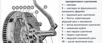
Of the drive parts in the figure, it is necessary to note the following components:
- reservoir for filling brake fluid (1), which is used as a filler for the hydraulic drive;
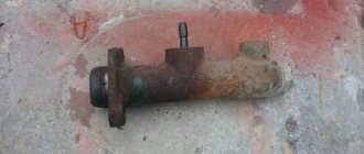
- clutch master cylinder (2);
- hydraulic pipes (3,4,5) and hose (7);
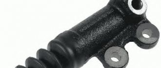
- clutch slave cylinder (8);
- pedal (6) and return spring (9).
Features of choosing mineral oil. Can it be used in a hydraulic clutch?
Mineral oil must adapt to the harsh operating conditions in gears, because the temperature can reach +150 C. Accordingly, strict requirements are imposed on oils, since in addition to performing the function of lubricating rubbing surfaces, they play the role of a working fluid.
Thus, mineral oil must have a sufficient number of performance qualities:
- high stability over the full operational life;
- mineral oil must have intensive aeration;
- high rates of foam formation;
- mineral oil must contain anti-corrosion additives that reduce the effect of corrosion;
- the optimal level of viscosity and density that mineral oil should have. If the level and efficiency are high, the viscosity index is minimal; if it is necessary to provide a film in the area of the friction surfaces, a high viscosity index is required;
- lack of aggressiveness in relation to parts used for compaction and in comparison with other elements operating in the system.
Often in practice, a special mineral oil is used, which is made on the basis of spindle components with a low viscosity level and the presence of additives.
However, it is worth paying special attention: in modern cars, mineral oil is not used in the clutch hydraulic drive, as it can destroy the rubber structural elements. For this purpose, special DOT4 brake fluid is used. It is also unacceptable to mix brake fluids of different types.
How does a hydraulic drive work?
Without touching on the design of individual components of this mechanism, we can return to this a little later; it is enough to familiarize ourselves with its operation in a simplified manner. We will assume that the required amount of brake fluid is filled into the drive, it is in good working order and fully operational.
When you press the pedal (6), the force is transmitted through the rod to the clutch master cylinder (2). He perceives this force, and then transmits it through a system of tubes and hoses to the clutch slave cylinder. The latter, through the clutch fork and release bearing, disconnects the transmission from the engine.
Car device
The clutch actuator is used for remote control of the clutch. The most widespread are mechanical and hydraulic drives.
The use of a particular drive on a car is determined by the type of clutch, the layout of the car and a number of requirements to ensure ease and convenience of control. Thus, the full travel of the clutch pedal should not exceed 190 mm, and the pedal force should not exceed 150 N for a passenger car and 250 N for a truck. Therefore, the total gear ratio in existing clutch drive designs ranges from 25 to 50. If a higher gear ratio is needed to ensure the clutch operates, amplifiers of various types are used.
***
Mechanical clutch drive
A mechanical clutch drive is simple in design and reliable in operation, but has lower efficiency compared to a hydraulic drive, since a lot of energy is lost in the articulated joints of the rods and levers that make up the drive, and in the shells of flexible shafts due to friction forces. Therefore, this type of drive is usually used if the clutch is located close to the controls (clutch pedal).
There are cable and lever mechanical clutch drives.
Cable drive (Fig. 1, a) is used on passenger front-wheel drive cars. The pedal 14 has an upper support on the bracket 16 and is connected to the tip 10 of the cable. The cable is enclosed in a sheath 1 having two ends. The upper tip 12 of the shell is brought into the car interior and rests against the thrust plate 11, and the lower tip 2 of the shell is fixed in the bracket 3 on the clutch housing. The lower tip 5 of the cable is connected through a leash 8 to the lever 9 of the clutch release fork. The pedal stroke is adjusted using washers 6.
When you press the clutch pedal, the cable moves inside the sheath and moves the clutch release fork lever, which subsequently acts on the clutch release clutch.
The lever drive of a truck (Fig. 1, b) ensures the transmission of force to the clutch when it is turned off as follows. When the pedal 14, attached to the shaft 20, is acted upon, the lever 18 connected to the opposite end of the shaft rotates. The shaft lever moves the rod 19 attached to it on the axis, which is connected to the lever 17 of the clutch release fork. The clutch release clutch, pressed against it by a spring, moves together with the fork. After selecting the gap between the clutch release bearing and the levers, the clutch will begin to disengage.
The clearance in the clutch should be 3...4 mm, which corresponds to 35...50 mm of free play of the clutch pedal. The gap is adjusted by changing the length of the rod 19 (Fig. 1) using the adjusting nut 22. The absence of a gap or its insufficient value in a drive of this design can lead to incomplete engagement of the clutch and, as a result, to clutch slipping. Increasing the gap beyond the norm leads to incomplete disengagement of the clutch, resulting in noise and crackling of the gears when changing gears.
***
How does the hydraulic drive work?
The design of the clutch master cylinder can be structurally designed in different ways, but in general the principle of operation is the same in all variants. As an example, the figure below shows a sectional view of the clutch master cylinder.
Among the main details are
- (2) - a pusher connecting the mechanism to the pedal;
- (3) master cylinder;
- (4) piston;
- plugs and return spring.
The figure shows that the clutch cylinder is divided into two parts by a partition. The upper half serves to fill the hydraulic drive with fluid entering the cylinder from the tank (5) and store its required working reserve. If everything is configured and adjusted correctly, then its level should be three quarters of the working volume.
The lower part serves as a working area. In the initial state, the piston (4) is pressed against the dividing wall by a spring, a gap A is formed between the pusher and the piston, and through it the liquid fills the working area.
When you press the pedal, the pusher, moving, closes gap A, the flow from the upper part to the lower part stops, the piston begins to move, transmitting force from the driver’s foot through a system of tubes and hoses to the working cylinder.
Due to the difference in the diameters of the piston and the outlet hole, its value increases, this becomes sufficient for the clutch to operate. This drive design makes it possible to lightly press the pedal to provide the required force to operate the entire mechanism.
When the pedal is released, the piston, under the influence of the spring and the pressure existing in the system, returns to its original position, and the pusher moves there, thereby restoring free penetration of liquid between the two parts of the cylinder.
What are the types of clutch drives and their operating principle?
The clutch drive on a car is designed to briefly disconnect the engine crankshaft from the gearbox, as well as to combine them, which are necessary for changing gears, as well as so that the car can move off and start moving.
Today, the following types of clutch drives are used in cars:
- mechanical clutch drive;
- hydraulic clutch drive;
- electrohydraulic drive.
The last of the above-mentioned clutch drives, unlike the first two, is used extremely rarely in cars and is used in robotic gearboxes. Therefore, we will not dwell on it more specifically, and let’s look at the first two.
Mechanical clutch drive
This drive is usually used in small passenger cars. It differs from other clutch drives in its low cost and simplicity of design, which consists of:
- clutch pedals;
- clutch cable;
- lever transmission;
- the mechanism responsible for regulating the free play of the clutch pedal.
Typical faults
Despite its simplicity, the master cylinder can also be a source of serious trouble. The most common causes of the defect may be:
- lack of working fluid;
- air entering the hydraulic drive system.
In the first case, you just need to check the liquid level in the tank; if it is insufficient, you need to add it to the set value. To avoid this, it is necessary to periodically monitor the position of the fluid in the tank during routine maintenance, as well as maintenance.
The reasons for air entering the master and slave cylinders, leading to clutch failure, may be cracks in the hoses, wear of parts, or leakage of the system at the junction of its various sections.
In order to restore the operability of the system, it is necessary to eliminate such sources of leakage and air entry into the line, the main and working cylinders, and also pump the entire system to remove air that has already entered from it. This procedure can be performed completely independently, without resorting to the help of a car repair shop. Due to the design features that the master cylinder has in different cars, it is difficult to describe this procedure correctly, although it can be briefly noted that it is carried out by pressing the clutch pedal. In this case, an additional hose is put on a special fitting or valve, through which the working fluid flows into a separate container with brake fluid.
Its level in the tank, to which the main cylinder is connected, should not fall below the set level, otherwise air may again enter. Along with the liquid, air leaves the system. When its bubbles stop releasing, we can assume that the system has been pumped and air has been removed from it. After this, everything is returned to its original state, the necessary adjustment of components and mechanisms is carried out (gaps and free movement are set).
The master cylinder is designed to transmit force from the pedal and convert its value to a value that should be sufficient to move the clutch fork. In this case, the clutch mechanism will operate and the connection between the engine and the wheels of the car will be broken.
Nuances of clutch operation
Often, drivers tend to associate unevenness and jerking when driving a car with clutch malfunctions. This logic is wrong in most cases.
For example, when a car shifts gears from first to second, the speed drops sharply. It is not the clutch itself that is at fault here, but the clutch pedal position sensor. It is located behind the clutch pedal itself. Sensor malfunctions can be eliminated through simple repairs, after which the clutch will again operate smoothly and without jerking.
Another situation: when changing gears, the car jerks a little, and when moving away it may stall. What could be the reason? Most often, the clutch delay valve is to blame. This valve provides a certain speed at which the flywheel can engage, regardless of how quickly the clutch pedal is "thrown" in. For novice drivers, this function is necessary, because... The clutch delay valve prevents excessive wear on the clutch disc surface.
Mechanical drive device
As already mentioned, the mechanical drive has an extremely simple structure and consists of the following structural elements:
- clutch pedal;
- cable;
- regulation device;
- lever drive;
- release bearing.
and so on until the system is filled with brake fluid. Attention! Under no circumstances should you pump the system, otherwise the new clutch will not work! It would be best to exclude independent replacement and adjustment of transmission components.
All cars equipped with a dry single-plate clutch must have a device that transmits force from the pedal to the clutch system.
To ensure the transfer of force, quite a few proposals have been developed. From the beginning, the force was transmitted from the pedal to the fork (lever device) via a cable, and the clutch fork squeezed the bearing. This way the clutch was released.
But with the development of the automotive industry, this system began to exhaust itself due to a decrease in free space in the engine compartment. And placing the clutch cable in a straight line and avoiding it rubbing against the engine part became increasingly difficult. This could negatively affect the comfort of driving and the inevitability of frequent repairs.
In the hydraulic system, instead of a clutch cable, high-pressure tubes are installed leading from the clutch master cylinder (MCC) to the working cylinder assembly with a release bearing, which is built into the gearbox. The liquid initially pumped from the expansion tank flows through the tubes from the GCS The device is similar to a brake system.
Operating principle of a hydraulic clutch.
By depressing the clutch pedal, the fitting pushes the fluid through the tubes to the working cylinder with a built-in bearing that presses the clutch. There are springs on the bearing that return it to the reverse position. By releasing the clutch pedal, the fluid flows back into the slave cylinder. You can see how the system mechanism itself works by following the VIDEO
The high-pressure pipes through which the fluid flows can be metal or plastic, depending on how far they are located from the engine parts. And as a rule, brake fluid moves through the clutch tubes, but this depends on the design nuances of the car manufacturer.
Adjusting the hydraulic clutch.
Bleeding the hydraulic system.
After replacing components of a transmission equipped with a hydraulic drive, it is necessary to bleed the clutch system. The principle is based on bleeding the car's brake system.
- By pressing the clutch pedal, the valve in the reservoir opens and transfers fluid to the main fluid circulation system.
- When you release the pedal, the fluid goes into the RCS (working cylinder)
and so on until the system is filled with brake fluid. Attention! Under no circumstances should you pump the system, otherwise the new clutch will not work! It would be best to exclude independent replacement and adjustment of transmission components.
After everything, do not forget to add brake fluid to the expansion tank.
To purchase a clutch, go to the CATALOG or Request by VIN . Or call us at the phone number listed in Contacts.
Today, the Electronic Clutch System is at the testing stage, so it is used to a limited extent, but in the future it may become very widespread.
Clutch release drive device
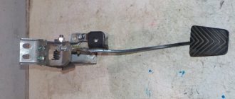
The stamped clutch pedal 21 is mounted on a welded bracket 12, fixed to the body with bolts 11 and studs 8 with nuts 7. The clutch pedal swings on an axis 16, which is fixedly fixed in the bracket 12. The pedal is secured against rotation by a flat that fits into a shaped hole in one of the cheeks pedal bracket.
The axial movement of the axis is limited by the cotter pin 13 and the shoulder of the flat. Two polyamide bushings 17 rotating on an axis, having collars at one of the ends, are inserted into the pedal hub.
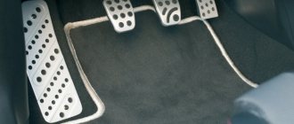
The bushings have high wear resistance and do not require lubrication during operation. A rubber pad 31 is put on the pedal platform. The pedal is held in its original (rearmost) position by the force of the tension spring 15. In this case, the non-adjustable pusher 14, pivotally connected to the pedal with a pin 19, rests against the limiting washer 5, fixed in the axial direction with a locking ring.
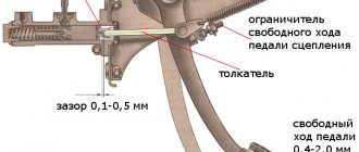
In the initial position of the pedal, the piston 12 of the clutch master cylinder under the action of the spring 8 abuts its end against the washer 14. Between the pusher 14 and the piston 4 there is a constant gap of a = 0.2 - 1.0 mm, which is ensured within the specified limits by the selected dimensions of these parts and the limiting washers 5.
The specified gap provides the piston of the master cylinder with the opportunity to take its original position (with the clutch engaged), guaranteeing communication between cavity a of the cylinder and the filling tank 3 through compensation hole b.
In clutch and foot brake control drives, pedal axles, polyamide bushings, pushers, pedal linings and fasteners are interchangeable. The clutch master cylinder is designed to create pressure in the hydraulic clutch drive system. The cylinder has a cast iron body 9 with an internal diameter of 22 mm with a figured flange; Two pins 18 are screwed into the flange, with the help of which the cylinder and pedal bracket 12 are attached to the front panel of the body. During assembly, up to four (as needed) adjusting shims 6, made of sheet steel 0.5 mm thick each, are installed between the cylinder body flange and the front body shield. These spacers help establish the initial position of the clutch pedal, which should ensure its full travel L until it touches the rubber floor mat, equal to 150-155 mm.
Rice. Clutch release drive: 1 — bracket for fastening the connecting tube; 2 — connecting tube; 3 — clutch master cylinder assembly; 4 — piston of the clutch master cylinder; 5 — limit washer; 6 — adjusting gasket; 7 and 28 - nuts; 8 — master cylinder mounting pin; 9 — supply tank for the clutch master cylinder; 10 — nut holder; 11 — bolt of fastening of the clutch pedal bracket; 12 — clutch pedal bracket: 13 — cotter pin for the clutch pedal axis; 14 — piston pusher of the clutch master cylinder; 15 — clutch pedal release spring; 16 — axis of the clutch and brake pedals; 17 — bushing for the clutch and brake pedal axle; 18 and 33 - washers; 19 and 23 - fingers; 20 and 32 — cotter pins; 21 — clutch pedal; 22 — clutch release fork; 24 — pusher tip; 26 — release spring for clutch release fork; 26 - lock nut; 27 — fork pusher; 29 — clutch operating cylinder; 30 — pin for fastening the working cylinder; 31 — pedal pad; 34 — protective cap; 35 — retaining ring; 36 — piston of the working cylinder; 37 — sealing collar; 38 — spacer mushroom; 39 — spring; 40 — air release valve; 41 — valve protective cap; 42 — tube fastening bracket; 43 — gasket
At the top of the master cylinder body there is a tank 3 made of translucent plastic. The reservoir contains a certain supply of brake fluid necessary for the normal operation of the hydraulic clutch drive. The tank is closed with a plastic threaded cap 1, in which there is a hole to communicate the internal cavity of the tank with the atmosphere, and a reflective plate is attached to prevent the brake fluid from splashing out through the specified hole. The flange of the strainer 2 rests on the end of the supply tank, which simultaneously functions as a damper for the brake fluid in the tank.
The nutrient tank 3 is attached to the main cylinder body 9 with a threaded fitting 4, which has a slot at the end for a screwdriver. The sealing gasket 5 after tightening the fitting guarantees the tightness of the connection between the tank and the cylinder body. Through the hole in fitting 4, brake fluid from reservoir 3 flows by gravity into housing 9 of the master cylinder.
A rubber sealing collar 13 is placed on the piston 12 located inside the cylinder, which prevents liquid from leaking out of the cylinder. The piston is cast from zinc alloy. There are six through holes in the piston head, covered with a thin steel ring-valve 11 and an internal working rubber cuff 10. On the outer surface of the cuff there is one annular and six longitudinal grooves. Spring 8 presses the cuff against piston 12, and the piston against thrust washer 14. The other end of the spring rests against threaded fitting 7, which closes the internal cavity of the cylinder body.