Problems with voltage in the on-board network are typical for many AvtoVAZ cars. They worry owners because they damage various electrical equipment to the point of making it impossible to operate the car. Therefore, motorists are interested in the question of how much a VAZ 2114 generator should produce.
In this article we will tell you what the voltage of the generator should be and how many amperes it is designed for. We will also look at the main causes of low and high voltage, their consequences, and ways to check the generator.
How many volts and amperes should the VAZ 2114 generator produce?
The generator of the “fourteenth”, like any other car, is designed to convert the energy produced by the motor into electric current. The electricity it generates powers all the electrical equipment of the car. For normal operation, the generator must have a certain current strength and produce the required voltage.
In this regard, many owners are interested in how many amperes the VAZ 2114 generator produces. If the car has a standard part, then it is designed for 90 A. question of how many volts a generator on a VAZ 2114 should produce is no less than 13-13.2 V. On average, this value is 13.6 V. But this is at full load. When consumers are turned off, it is much higher.
How to remove the generator
Removal
Genadiya in Samara through the top without straining.
- In order to remove the generator, you will need to drive the car into a pit or lift it on a lift. For ease of operation, it is necessary to remove the crankcase protection. The next step is to remove the terminal from the car battery.
- Moving the rubber boot to the side, you can see the nut that attaches the positive terminal to the generator. It should be unscrewed and the wire block disconnected. This may require some force.
- Using a socket wrench or wrench, unscrew the adjusting bolt.
- Find the nut of the bolt located on top. It is thanks to him that the generator is held on the bar. Both the nut and bolt should be removed while simultaneously removing the tension bar that holds the bolt.
- Finally, you need to unscrew the nut of the bolt located below. Directly behind this nut there is a spacer sleeve that will also need to be removed.
- Next, using milk, you should knock out the bolt from the generator, but at the same time the latter must be held suspended.
What generator is installed on the VAZ 2114?
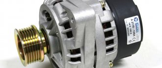
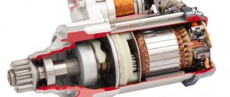
Having figured out what voltage the generator on the VAZ 2114 should produce, it’s worth understanding what kind of device produces it. This domestic hatchback is equipped with a three-phase generator type 94.3701 . It consists of a stationary winding or stator, a rotor, rotor bearings, an impeller, and a pulley for putting on a belt. It also has a diode bridge or rectifier, a voltage regulator and a housing.
Russian-made devices of the KZATE brand were installed on the car from the factory. Also, on some cars of recent years of production you can find standard German Bosch. Despite the fact that domestic generators, with proper care, can be used for a relatively long time, foreign-made parts are considered more reliable. Therefore, when replacing, many owners buy products from this or another foreign brand. In addition, sometimes more powerful generators are installed. They are purchased, for example, by car audio enthusiasts, since the factory ones are not designed for such a heavy load.
Useful : Where is the VAZ 2114 generator fuse located?
WHAT IS A GENERATOR?
The VAZ 2114 generator can be imagined as an electric three-phase alternating current machine. It has a built-in rectifier unit that converts alternating current to direct current. The device consists of the following parts:
- Front and back cover made of aluminum alloy. Each of them has slots for installing bearings. On the back cover body there is a battery connection terminal and a connector for supplying voltage to the excitation winding. There is also a capacitor installed on the back cover, which suppresses radio interference; there is a place for installing and fastening the brush assembly;
- Stator core cylinder made of transformer iron. Inside it there are grooves for laying the power windings of the generator. They have leads for connection to the rectifier block. Both covers are attached to the stator with four bolts;
- Excitation winding on the rotor shaft. It is connected with its leads to slip rings made of copper, which are installed on the same shaft. The front of the shaft has a keyway to accommodate the drive pulley;
- The brushes of the VAZ 2114 generator are a non-separable unit combined with an electronic relay controller. The relay in a metal case is riveted to the brush holder;
- A block of power and additional diodes is attached to the back cover from the inside. It contains six power and three additional diodes. To cool semiconductor devices, they are mounted on horseshoe-shaped aluminum alloy plates.
Generator set design
SOME OF ITS TECHNICAL CHARACTERISTICS
The generating set provides the following parameters:
- The excitation winding is powered by an adjustable voltage from 13.2V to 14.7V;
- The current strength of the voltage generated by the generator is 80 A;
- The belt deflection should not exceed 8 mm with a load of 10 kg.
The generator is installed on the engine on its left side in the direction of travel of the machine. The rotor rotates right, which it receives using a drive belt from the engine crankshaft.
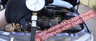
How to measure generator voltage?
Knowing what voltage the generator should produce, you also need to be able to measure it. Otherwise, it will be impossible to understand that it is too low or prohibitively high. There are two ways to measure voltage. The first one is very simple, but imprecise. The car's on-board computer shows the voltage. Therefore, you can simply look at his testimony. Unfortunately, they are often underestimated. Therefore, you should not rely on these data to accurately diagnose the generator. In addition, sometimes the voltage on the on-board computer fluctuates under load. But this is not always a reason to troubleshoot. Perhaps one of the consumers is too powerful or connected incorrectly. Or is it just a device error.
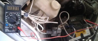
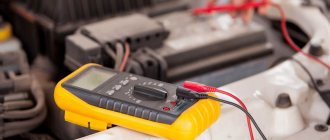
The second method gives the most accurate result. To do this you will need a multimeter and an assistant. The measurement is performed in the following sequence:
- Turn on the ignition and make sure that all warning lights on the dashboard light up as normal;
- Start the car and check that the battery indicator goes out. If the battery icon is on, it means the generator, battery or wiring problems are faulty;
- Warm up the car to operating temperature and turn on all available electrical consumers;
- Take a multimeter and set it to voltmeter mode;
- Ask an assistant to maintain engine speed within 3500;
- The multimeter is connected to the battery;
- Evaluate the measurement result. If everything is in order, the multimeter will show approximately 13-13.2 V or a little more. If the readings are lower, the generator or battery is faulty.
Next, you should carry out the same check with the consumers turned off. With a working generator, the voltmeter will show about 14.5-14.7 V.
To diagnose the generator, you need to connect a multimeter to its terminals. The device should display values in the range of 14-14.3 V. Then you should ask an assistant to increase the engine speed. The voltage of a working generator should not jump by more than 0.5 V. If it changes or was initially lower or higher than expected, the unit needs to be repaired.
HOW TO REMOVE THE GENERATOR FROM THE CAR
It is installed in a special bracket on the cylinder block; there is also a bar for tensioning the generator belt. Find the generator in the front part of the engine compartment on the right side in the direction of travel of the car. To remove it, you need to prepare the following tools:
- Wrench set to “10”;
- The same key for "13"
- Open-end wrench 17x19;
- Head at "15"
- Mount.
We remove and do not touch the engine protection.
Removal is carried out in several ways, where it is necessary to remove the engine protection. They are well described in various sources. Let's try to remove it without removing the protection. The procedure will be as follows:
- The first step is to disconnect the terminals from the battery;
- Loosen the belt tension, remove first the belt, and then the entire tension mechanism;
- Disconnect the wires from the battery, they are covered with a rubber cover, and the connector for supplying voltage to the excitation winding;
- The generator on the bracket is mounted on a long bolt and nut. It’s not very convenient to get it, so use a “15” head to unscrew the two bolts securing the bracket to the block. They are found at the back of the generator, one bolt is long and the other is shorter. Now the generator can be turned clockwise and it will be possible to remove the axis of its attachment to the bracket;
- Unscrew the nut with a wrench to “19” and remove it together with the spacer sleeve;
Use a small punch or something similar to knock the axle out of the bracket. The generator is lifted up. Now you can use it to repair the generator or perform maintenance.
Recharging the battery
Sometimes when the generator breaks down, the battery overcharges. This can be noticed not only when taking measurements with a multimeter, but also in the readings of the on-board vehicle. And if the set voltage is greatly exceeded, various electrical equipment may fail or the battery may boil out. Also, the headlights may shine brighter than usual, and the battery charge indicator on the dashboard will constantly light up. These are the main symptoms of overcharging. It occurs most often due to a faulty voltage regulator. This part on the VAZ 2114 can be easily changed with your own hands.
And the battery and generator diagnostics described above will help determine the exact presence of the problem.
VAZ 2115 Generator malfunctions
8.1.4.1. Generator faults
Also check with the indicator that there is voltage at the large generator connector. It should always be here - if it is not, then check the connection of the generator to the battery. If the voltage regulator on your car is located separately from the alternator, then it may also be faulty. In this case, it is better to remove the generator and voltage regulator and contact an auto electrician.
The simplest way to check the generator load current is to turn on the car's side lights and start the engine. If the lights do not become brighter while the engine is running, then this is the best evidence that the alternator is not delivering current. If you have a voltmeter, connect it to the battery terminals and start the engine. At high idle speeds, the generator should produce current, and the voltmeter should show about 14 V. Do the readings differ by more than 1 V? Either the generator or the voltage regulator is faulty.
In many cases, a constant light on the control light indicates a malfunction of the generator, but problems are possible in other places, and the generator, paradoxically, may be working properly at this time.
And yet, for most car owners, the warning light is the only indicator of the health of the generator. The most common causes of abnormal functioning of the charge warning lamp and typical situations are shown in the table. For example, the line “The warning lamp does not light up” implies that the ignition should already be on, and at the same time it does not mean that the engine should be running. Generator malfunctions are listed in order of increasing likelihood of their occurrence. Faults in italics are not directly related to the generator. Below is a table that explains what some of the above problems can cause.
Typical faults indicated by the charge indicator lamp
Lights up dimly when starting the engine
Flashes when the engine is running
The generator produces low voltage
Unlike overcharging, which is observed infrequently, owners of the “four” often encounter low voltage in the on-board network. It can be determined not only by readings on the dashboard or by measurements with a voltmeter. The most common symptoms of this problem are:
- Constantly lit battery indicator on the dashboard;
- Low voltage on the on-board computer (although it often lies a lot);
- Dim or flickering headlights and dashboard lights;
- Failure of electrical appliances or their unstable operation;
- Intermittent engine operation;
- The engine stalls while driving;
- Difficulty starting the engine or inability to start it.
Most often this occurs due to a failure of the voltage regulator or diode bridge. But the voltage can also be low due to a short circuit in the stator winding, bearing wear and some other generator failures. But, before repairing or replacing it, you need to make sure that the problem is in the generator set. Sometimes similar symptoms are caused by a faulty battery or poor wiring or oxidized terminals. In addition, the car may have powerful additional electrical equipment, such as an expensive radio, amplifier, or subwoofer. You should make sure that it is working and connected correctly. Or perhaps the generator simply does not have enough power for such consumers.
Generator breakdowns
All breakdowns that occur with current-generating devices can be divided into mechanical and electrical. The first includes factory defects in components, excessive tension or too much slack in the drive belt, as well as wear or complete destruction of bearings.
Generator bearing wear
Electrical faults include the generated voltage being too high, the generated voltage being too low, or a complete loss of voltage.
No voltage
Test of automobile generators KZATE, LKD, Fenox, "Pramo" and "StartVOLT"
Every motorist who is interested in the design of his iron horse knows that the main source of electricity in the electrical equipment of any car is a power plant, which includes a battery, a generator and a relay regulator. The battery is the main one in this trio. It powers the entire on-board network of the car, and the generator with a relay regulator, to the extent possible and necessary, feeds the battery and ensures that the on-board network of the car does not exceed the specified voltage (for cars with 12-volt equipment, this voltage is 14-14 .6 V, and for 24-volt - 27-28.8 V). And although generators in a car are long-lasting items, they sometimes fail. Let's see what the Russian market offers us to replace a failed generator, and at the same time test the proposed models in our testing laboratory.
To begin with, a small educational program. The generator is necessary for uninterrupted charging of the constantly discharged battery by electrical appliances included in the vehicle’s on-board network. Modern cars are equipped with alternating current generators. They best meet the requirements for one of the most important power components of a car.
The generator converts mechanical energy received from the engine into electrical energy. The voltage regulator (in the vast majority of modern cars is an integral part of the generator, with rare exceptions when the regulator is “remote”, that is, placed in the engine compartment, separately from the generator) maintains the voltage of the vehicle’s on-board network within specified limits when the electrical load and rotation speed change generator rotor and ambient temperature.
A car generator must provide an uninterrupted supply of current and have sufficient power to:
- supply electricity to the battery, which is constantly discharged by working on-board consumers;
- When all regular electricity consumers were turned on at low engine speeds, the battery did not discharge.
In addition, the generator must have sufficient strength, a long service life, small weight and dimensions, low noise levels and radio interference.
Summarizing all of the above, we can conclude that the generator is the heart of the car’s electrics, which must always “beat” and provide current for charging in order for the car to “live.”
Understanding the importance of this automotive unit, we turned our attention to the market of generators for domestic cars.
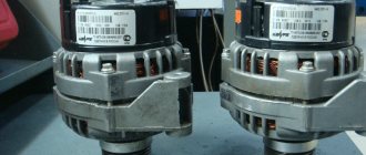
For a comparative test, we purchased five car generators from a regular spare parts store. These are generators of the KZATE, LKD, Fenox, Pramo and StartVOLT brands. All of them are designed for installation on VAZ car engines.
Alternating current generator 9402.3701-01 with built-in rectifier unit and analog voltage regulator (14 V; 80 A; 1.12 kW; 1200/6000 min-1; 4.9 kg) - JSC "Plant im. A. M. Tarasov" (JSC "ZiT") - KZATE brand (Russia)
This generator is considered standard, since it is the generators of this plant that are supplied to the AvtoVAZ conveyor.
The build quality did not raise any complaints. The generator is repairable.
A little about the evaluation methodology: to measure the current-voltage characteristics, the generators were installed on a specialized stand. Generators must provide the maximum current strength at crankshaft speeds from 1500 to 2500.
At 700 crankshaft revolutions per minute, this generator showed a current value of within 40 A with a predisposition to “attenuation”. When reaching the nominal speed, the KZATE generator confirmed the declared 80 A and even reached 90 A. Assessing the reviews of motorists, we can say with confidence: this generator is a variant of the classic reliable design without a claim to outstanding performance, but guaranteeing trouble-free operation.
Testing of the KZATE generator at 700 rpm of the engine crankshaft
Testing of the KZATE generator at 2000–2500 rpm of the engine crankshaft
Alternating current generator 9402.3701 P with built-in rectifier unit and analog voltage regulator (14 V; 100 A; 1.4 kW; 1200/6000 min-1; 4.85 kg) - LKD Electrical (China)
The LKD generator almost completely repeats the design of the KZATE generator described above. It is characterized by the same features in terms of workmanship and maintainability.
However, even when installed on the stand, the LKD generator showed its complete inoperability. When identifying the cause of the failure, a lack of soldering was discovered on the supply wire of the regulator relay. When considering the future fate of the generator, we decided to exclude it from the tests. Even though troubleshooting could take several minutes, we decided to take the consumer's position. Having paid money, the consumer does not have to independently eliminate the manufacturer’s defects and carry out modifications on his own.
LKD generator lack of charge
Subsequently, we took an interest in consumer reviews on the Internet for this generator and found other negative responses to this test subject, with the only difference being that someone had to pay a little more for it.
Alternator AL 21305 with built-in rectifier unit and analog voltage regulator (14 V; 80 A; 1.12 kW; 1200/5500 min-1; 5.6 kg) – Fenox Global Group (Belarus)
The Fenox brand generator is identical in design to the two described earlier. However, upon inspection of this generator, higher quality workmanship was found. Maintainability at the same level requires the intervention of a trained specialist. Knowing the “sores” of such generators, we checked the tightening of the contacts. As it turned out, it was not in vain. If they had not been tightened, the consequences would have been sad, albeit in the foreseeable future: melting of the contacts due to the formation of transient resistances during the passage of high currents, subsequent failure of the unit. In fact, this is more of a prevention than a crime. All generators were subjected to this procedure.
Bench tests of the Fenox generator showed the following results. When operating at 700 crankshaft revolutions per minute, it was possible to achieve values at the level of 45-50 A with obvious signs of “damping”. When the crankshaft speed increased to 2500, the generator produced 90 A under load, but that was all.
Fenox generator testing at 700 rpm engine crankshaft
Testing the Fenox generator at 2000-2500 rpm of the engine crankshaft
Alternating current generator 5102.3771 with built-in rectifier unit and analog voltage regulator (14 V; 100 A; 1.4 kW; 1200/5500 min-1; 5.4 kg) - JSC Concern Pramo (Russia)
The design of the Pramo brand generator is somewhat different from the previous three: a different casting is used, a different design of bearing supports is used. Securing the bearings using flanges, among other things, made it possible to significantly increase the maintainability of the unit. To repair the bearing assembly of this generator, you can attract specialists with less qualifications.
The diode bridge of the generator also differs in design. The design exactly copies the design used in Bosch generators. But the diode bridge itself is not repairable. The leads from the stator winding are sealed on a diode bridge. In general, maintainability is sacrificed for stable contact.
Bench tests of the Pramo generator showed the following results. When operating at 700 crankshaft rpm under load, a value of 50 A was achieved. When the crankshaft rpm increased to 2500, the generator reached a value of 100 A under load.
Testing the "Pramo" generator at 700 rpm of the engine crankshaft
Testing the "Pramo" generator at 2000-2500 rpm of the engine crankshaft
Alternating current generator "StartVOLT" LG 0110 with a built-in rectifier unit and digital voltage regulator (14.6 V; 120 A; 1.9 kW; 1200/5500 min-1; 5.3 kg) - Carville LLC (St. Petersburg)
In design, the StartVOLT brand generator is very close to such representatives as KZATE, LKD and Fenox. Its diode bridge is also similar to them, with the exception of the presence of two additional power diodes designed to produce additional power take-off, as the developer states. This is the so-called use of the third harmonic, which is simply not used in other generators.
The stator winding terminals do not have mechanical contacts. The stator winding leads are sealed on a diode bridge. The relay-regulator, unlike all those described above, is digital, not analog, again according to the manufacturer, and it is also assumed that, among other things, “a field-effect transistor is installed on the output switch, which has zero resistance when opening, which ensures a decrease losses."
The bearing units are also similar to the designs of the KZATE, LKD and Fenox generators.
And the most important significant difference from all previous models is the declared current of 120 A!
We did not take the manufacturer’s word for it, but bench tests of the StartVOLT generator showed the following results: when operating at 700 crankshaft rpm under load, we managed to achieve a value of 60 A. Amazingly, when the crankshaft rpm increased to 2500, the generator reached the declared value of 120 A under load! De facto, this is almost 50% more than that of a standard KZATE generator.
Testing of the StartVOLT generator at 700 rpm of the engine crankshaft
Testing of the StartVOLT generator at 2000-2500 rpm of the engine crankshaft
So, let's sum up the intermediate results. With almost identical designs, the “zest” of the StartVOLT generator made it possible to achieve 30-50% better performance than that of potential competitors. All we have to do is summarize the measurement data in a table, enter prices and expert assessments.
CONCLUSIONS
The classic model of a standard generator from KZATE is in demand among motorists, although it cannot be said that the increased need for more powerful generators is a requirement of the time. Therefore, this model, despite its quality and the level of the manufacturer itself, is morally outdated. Therefore, our choice fell on the generator as it is more interesting in terms of real characteristics.
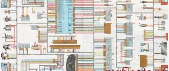
Wiring diagram VAZ 2115
It is difficult to imagine a modern Lada Samara car without electrical appliances. Generator connection diagrams, high or low beam lights, lighting in the car interior, air conditioning and other systems - this is the wiring of the VAZ 2115. The Samara is based on the 99 Zhiguli model with a modified appearance and a new engine. The latest innovation led to improvements in the electrical wiring of the machine. The changes also affected the connectors of the devices that make up the electrical circuit and the wiring diagrams inside the machine.
Lada Samara is equipped with two types of engines. You can choose a 1.5 m3 carburetor power plant (VAZ 2115-01) or a VAZ 2115 injector of the same volume. The wiring of the VAZ 2115 directly depends on what engine is installed on the Lada Samara model. If there is an injector, a circuit with one leading wire is used. Negative contacts are output to the housing, and positive contacts are connected to separate conductors.
The electrical wiring of the VAZ 2115 is installed depending on the type of engine installed in the car. With an engine that has 8 valves and distributed fuel injection, the car has more electronics and additional sensors and devices. And in this case, the wiring harnesses that make up the electrical wiring of the VAZ 2115 will be thicker.
Maintenance of the electrical wiring system in Lada Samara
In a car with an injection or carburetor engine, maintenance of electrical wiring consists of protecting and repairing it. The electrical equipment in the car will last a long time, and it will only have to be repaired as a last resort if you carefully ensure that no moisture gets into the wiring system, and that high-voltage wires are not tangled and are located as far as possible from the hot parts of the engine. The VAZ 2115 electrical diagram will help with this.
You need to pay special attention to the condition of the contacts and connectors; if necessary, they should be cleaned of dirt and dust. Burnt-out sections of wiring should not be replaced; it is much better to change the entire wire
The VAZ 2115 wiring diagram will become a visual aid and will help you carry out minor repairs yourself or even completely replace the electrical wiring in the car. The VAZ 2115 diagram is clear and intuitive to the user; its especially important details are highlighted in color or a different font.
Without a diagram of the location of electrical components in a machine with 8 valves, it is impossible to repair or replace the main relay or other unit.
Checking the main relay in a Lada Samara car
One of the most important parts of the VAZ 2115 electrical wiring is its main relay. Before replacing any part in a car, you first need to determine where it is located. And to understand this, you will need a wiring diagram. As for the main relay in the VAZ 2115, it is installed next to the fuel pump and the system that includes radiator cooling. Fuses responsible for the operation of the engine and fuel system are also usually installed there.
When the ignition is turned on, the relay should make a clicking sound. If this does not happen, you need to check that there is power on contacts 85 and 86 of the main relay. This is done using a test lamp, which is connected to the minus. The control current consumption should not be higher than 0.25 A, otherwise the controller may be damaged. If the light on one of the outputs does not light up, the relay is disconnected from electricity. This happens when a fuse blows or when the supply wire breaks.
It happens that the lamp on one of the terminals burns brighter, and the relay is triggered. Then you need to turn off the ignition, remove the relay from the connector, connect contacts 85 and 86 with a control, and the lamp will light up normally. If this does not happen, you need to check the connection between the relay and the block. When this does not help, you should ensure the integrity of the conductor connecting the relay to the controller, and also check the connections of the controller wires to the motor housing. On the Lada Samara, these contacts are located at the end of the cylinder head, directly above the thermostat.
On cars manufactured by AvtoVAZ, when the main relay does not function, you can use the most suitable part from the mounting block to test the system. Relays for turning on signals, low beam or high beam headlights are suitable.
When troubleshooting problems due to which the main relay does not turn on, it is necessary to take into account the possibility of anti-theft systems in the car. When installing them, blocking blocks are often included in the relay circuit, which break the power circuit when the alarm is triggered.