Welcome, friends, to the DIY car repair website. The generator is, without exaggeration, the key component of a car. Its task is to power the entire electrical part of the vehicle while driving (cassette recorder, head light, navigator, and so on).
How to check a generator diode bridge
When the generator fails, the entire load is transferred to the battery. As a result, after just a few hours the car is completely immobilized.
Most car enthusiasts immediately go to a service station, where they spend a lot of money on repairs. Take your time - the problem in 90% of cases lies on the surface.
If you know how to test a generator diode bridge, you can quickly identify the problem, fix it and save money.
Removing and replacing a diode bridge on a VAZ 2101, 2102, 2103, 2104, 2105, 2106, 2107 (video)
Hello, from this article you will learn how to replace the diode bridge on VAZ 2101, 2102, 2103, 2104, 2105, 2106, 2107 cars. The diode bridge in the generator plays a key role, therefore, if it fails, the generator will not produce charge and soon the car’s battery will run out.
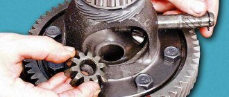
In principle, it is the burnt diode bridge that in most cases damages the generator. To replace the diode bridge, you will need to remove the generator from the car. To disassemble the generator and remove the diode bridge, you will need heads 8 and 10. First of all, you need to disassemble the generator into 2 parts; to do this, unscrew the nuts on the bolts that hold the generator housing together
Next, carefully tap one of the parts of the generator with a hammer to disassemble it.
The next step is to unscrew the head with an extension nut securing the diode bridge and, disconnecting the block from the generator, remove it
Installation of a new diode bridge occurs in the reverse order.
Source
How to check a diode bridge with a multimeter and a test lamp
Let's start with the fact that checking the diode bridge of the generator can be done in two ways. One requires the presence of a tester (multimeter), while the second is performed using a 12 V test lamp.
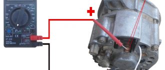
- Let's start with the simplest method with a lamp. First you need to connect the diode bridge (diode bridge plate) to the negative terminal of the battery. The plate must be pressed tightly against the generator body.
Next, take a known working light bulb with wires, which with one end of the wire is connected to the “plus” of the battery, while the other end of the wire is connected to the output terminal of additional diodes. Then the connection is made to the “+” terminal bolt, as well as to the connection points of the stator winding.
If the light starts to light up, this clearly indicates that the diode bridge has burned out or broken. By the way, an additional check of the diode bridge for a break is performed as follows:
You need to connect the “minus” of the test lamp to the “plus” of the battery, the other end of the test light to the “minus” of the battery. Next, the lamp is connected at the contact points described above. However, in this case the llama should burn brightly. If this is not the case (the control light does not light up or the glow is very weak), this will indicate a break in the diode bridge.
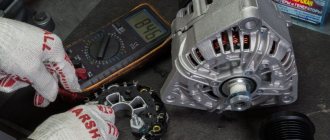
- Checking the diode bridge with a multimeter will require removing the entire bridge from the generator. In this case, the method is more accurate, since each diode is checked separately by the tester.
To check, the multimeter is set to the so-called “ringing” mode. In this mode, the device makes a sound when two electrodes are connected. If there is no sound notification, then the mode is set to 1 kOhm.
Next, the electrodes of the multimeter are connected to the two ends of the diode, after which the probes are swapped. Normally, the diode should show 400-700 Ohms in one direction, while infinity in the other.
If infinity is shown in both directions when ringing, this indicates that the diode has broken. If there is resistance, but it is weak or the same on both sides, in this case the diode is broken. Now let's look at this method in more detail.
Checking the diode bridge with a multimeter
Before starting diagnostics of the generator, the device itself must be cleaned of dirt and prepared. The check should begin by removing the protective casing, then disconnecting the regulator leads. Please note that positive diodes are marked in red, negative diodes are marked in black.
During testing, the tester first checks the entire circuit of additional diodes. If problems are found, then each diode must be ringed individually. To check, the positive probe of the tester is connected to the diode bus, and the negative probe to the desired diode.
As mentioned above, if the generator diode is normal, the readings on the device will show infinity, and after rearranging the probes, the required resistance will appear. If the readings differ from the norm, the diode or the entire bridge must be replaced. In a similar way, you can check a circuit of positive and negative diodes by ringing each one.
Technical characteristics of the VAZ 2105 generator
Starting in 1986, 37.3701 generators began to be installed on “fives”. Before this, the car was equipped with the G-222 device. The latter had different stator and rotor coil data, as well as a different brush assembly, voltage regulator and rectifier. The generator set is a three-phase mechanism with excitation from magnets and a built-in rectifier in the form of a diode bridge. In 1985, the relay responsible for indicating the warning light was removed from the generator. The on-board network voltage was monitored only using a voltmeter. Since 1996, the 37.3701 generator has received a modified design of the brush holder and voltage regulator.
Table: parameters of generator 37.3701 (G-222)
| Maximum output current (at a voltage of 13 V and a rotor speed of 5 thousand min-1), A | 55(45) |
| Operating voltage, V | 13,6–14,6 |
| Engine-generator gear ratio | 2,04 |
| Direction of rotation (drive side) | right |
| Generator weight without pulley, kg | 4,2 |
| Power, W | 700 (750) |
What generators can be installed on a VAZ 2105
The question of choosing a generator for a VAZ 2105 arises when the standard device is not capable of providing current to the consumers installed on the car. Today, many car owners equip their cars with powerful headlights, modern music and other devices that consume high current.
The use of an insufficiently powerful generator leads to undercharging of the battery, which subsequently negatively affects engine starting, especially in the cold season.
To equip your car with a more powerful source of electricity, you can install one of the following options:
- G-2107–3701010. The unit produces a current of 80 A and is quite capable of providing additional consumers with electricity;
- generator from VAZ 21214 with catalog number 9412.3701–03. The current produced by the device is 110 A. For installation, you will need to purchase additional fasteners (bracket, strip, bolts), as well as make minimal changes to the electrical part;
- product from VAZ 2110 for 80 A or higher current. For installation, a suitable mount is purchased.
Diode bridge: check
So, problems with the generator can lead to the battery not charging. This leads to its deep discharge. Also, failure of individual elements of the generator can lead to overcharging of the battery, boiling off of the electrolyte, damage to the battery, etc.
In any case, before replacing the battery, it is necessary to check the generator itself. If the problem is not with the brushes or bearings, then the diode bridge may be the culprit.
Note that it is useful for every car owner to know how to check the diode bridge with their own hands. Please note that the method discussed below can be used to perform such a check in a regular garage.
Generator device
The main structural elements of a car generator are:
To know how the generator functions, you need to understand the purpose of each element in more detail.
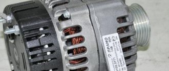
On the VAZ 2105, the generator is installed in the engine compartment and is driven by a belt from the engine crankshaft.
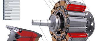
Rotor
The rotor, also known as the armature, is designed to create a magnetic field. On the shaft of this part there is an excitation winding and copper contact rings, to which the coil leads are soldered. The bearing unit, installed in the generator housing and through which the armature rotates, is made of two ball bearings. An impeller and a pulley are also attached to the rotor axis, through which the mechanism is driven by a belt drive.
Stator
The stator windings create an alternating electric current and are combined through a metal core made in the form of plates. To avoid overheating and short circuits between the turns of the coils, the wires are coated with several layers of special varnish.
Frame
The generator housing consists of two parts and is made of duralumin, which is made to facilitate the design. To ensure better heat dissipation, holes are provided in the housing. By means of an impeller, warm air is expelled from the device to the outside.
Generator brushes
The operation of a generator set is impossible without elements such as brushes. With their help, voltage is supplied to the rotor slip rings. The embers are enclosed in a special plastic brush holder and installed in the corresponding hole in the generator.
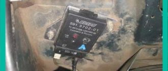
Voltage regulator
The relay-regulator controls the voltage at the output of the unit in question, preventing it from rising above 14.2–14.6 V. The VAZ 2105 generator uses a voltage regulator combined with brushes and fixed with screws on the back of the power source housing.
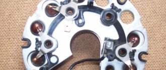
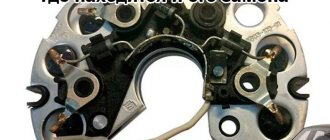
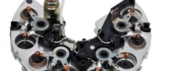
Diode bridge
The purpose of the diode bridge is quite simple - to convert (rectify) alternating current into direct current. The part is made in the shape of a horseshoe, consists of six silicon diodes and is attached to the back of the case. If at least one of the diodes fails, the normal functioning of the power source becomes impossible.
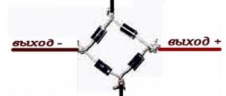
Diode bridge functions
For charging and normal operation of the battery, direct current is required, but the generator produces only alternating current. To make the desired conversion, a diode bridge is used. The electronic components included in this unit conduct current in only one direction, rectifying it. The resulting voltage drops are smoothed out by the battery, “replacing” the capacitor. The functions of valves are most often performed by silicon diodes. However, it is possible to use other types of rectifiers - for example, selenium pillars.
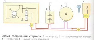
Operating principle of the generator set
The “five” generator functions as follows:
- When the ignition is turned on, power from the battery is supplied to terminal “30” of the generator set, then to the rotor winding and through the voltage regulator to ground.
- The plus from the ignition switch, through the fuse-link “10” in the mounting block, is connected to contacts “86” and “87” of the charge warning lamp relay, after which it is supplied through the contacts of the switching device to the light bulb and then to the minus of the battery. The light is on.
- As the rotor rotates, a voltage appears at the output of the stator coils, which begins to power the excitation winding, consumers and charge the battery.
- When the upper limit of the voltage in the on-board network is reached, the relay regulator increases the resistance along the excitation circuit of the generator set and keeps it within 13–14.2 V. Then a certain voltage is supplied to the winding of the relay responsible for the charge lamp, as a result of which the contacts open and the light goes out. This indicates that all consumers are powered by the generator.
Voltage Regulator Diagnostics
To check the voltage regulator on a VAZ 2114, 2106 car, you should perform the following steps:
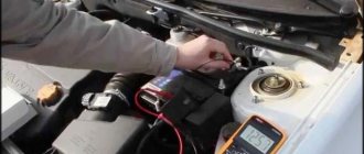
- Start and warm up the engine by turning on the headlights. Warm up the engine for about 15 minutes. For diagnostics, a multimeter or voltmeter capable of taking measurements in the voltage range 0-15 V is used.
- Measure the voltage between ground and terminal 30. For most cars in normal condition, the reading will be within 13.5-14.6 V. A value less than 13 V means the unit needs to be replaced.
Generator faults
The Zhiguli generator is a fairly reliable unit, but its elements wear out over time, which leads to problems. Malfunctions can be of various types, as evidenced by characteristic signs. Therefore, it is worth dwelling on them, as well as on possible problems, in more detail.
The battery discharge light is on or flashing
If you observe that the battery charge light on a running engine is constantly on or flashing, then there may be several reasons for this behavior:
- insufficient tension of the generator belt drive;
- open circuit between the lamp and the generator;
- damage to the rotor winding power supply circuit;
- problems with the relay regulator;
- brush wear;
- damage to diodes;
- break or short circuit in the stator coils.
No battery charge
Even when the generator is working, the battery may not be charged. This may be due to the following reasons:
- the generator belt is loose;
- unreliable fixation of the wiring to the generator or oxidation of the terminal on the battery;
- battery problems;
- problems with the voltage regulator.
Generator check
If problems occur with the generator set, a unit check must be performed to determine the cause. This can be done in several ways, but the most accessible and common is using a digital multimeter.
Diagnostics with a multimeter
Before starting the test, it is recommended to warm up the engine at medium speed for 15 minutes, turning on the headlights. The procedure is performed as follows:
- We turn on the multimeter to measure voltage and take a measurement between terminal “30” of the generator and ground. If everything is in order with the regulator, then the device will show a voltage in the range of 13.8–14.5 V. If the readings are different, it is better to replace the regulator.
- We check the regulated voltage by connecting the probes of the device to the battery contacts. In this case, the engine should operate at medium speeds, and consumers should be turned on (headlights, heater, etc.). The voltage must correspond to the values installed on the VAZ 2105 generator.
- To check the armature winding, connect one of the multimeter probes to ground, and the second to the rotor slip ring. At low resistance values, this will indicate a faulty armature.
Video: diagnosing a generator with a light bulb and a multimeter
To be able to constantly monitor the battery charge voltage, I installed a digital voltmeter in the cigarette lighter, especially since I am not a smoker. This device allows you to always monitor the voltage of the on-board network without leaving the car and without lifting the hood to take measurements. A constant voltage indication immediately makes it clear that everything is in order with the generator or, conversely, if problems have arisen. Before installing the voltmeter, more than once I had to deal with problems with the voltage regulator, which were detected only when the battery was discharged or when it was being recharged, when the liquid inside simply boiled due to the excess of the output voltage.
At the stand
Diagnostics at the stand are carried out at the service, and if everything necessary is available, it is also possible at home.
- We mount the generator on the stand and assemble the electrical circuit. On the G-222 generator we connect pin 15 to pin 30.
Oscilloscope
Generator diagnostics are possible using an oscilloscope. However, not everyone has such a device. The device allows you to determine the health of the generator based on the signal shape. To check, we assemble the same circuit as in the previous diagnostic version, after which we perform the following steps:
- On the generator 37.3701, we disconnect the “B” terminal from the diodes from the voltage regulator and connect it to the battery positive through a 12 V car lamp with a power of 3 W.
- We turn on the electric motor on the stand and set the rotation speed to about 2 thousand min-1. We disconnect the battery using the toggle switch “6” and set the output current to 10 A using the rheostat.
- Using an oscilloscope, we check the signal at terminal “30”. If the winding and diodes are in good condition, the shape of the curve will be in the form of uniform saw teeth. In case of broken diodes or a break in the stator winding, the signal will be uneven.
Trouble-shooting
There are two main options for solving the problem. The first is accurate diagnostics on the bench: after detecting signs of burnt-out diodes, a check is carried out and it is determined which elements have failed. After this, the faulty diodes are soldered off, and new ones are soldered in their place. It is very important to take exactly the same brand; any analogues will not last long.
It is much easier to change the assembly, it is faster and of better quality, since you can be sure that the spare part will last for some time. The price of the part is low, for example, on a VAZ 2110 it is about 650 rubles. Replacement is not difficult and can be done independently.
Identifying a faulty diode bridge and replacing it is not difficult for any car enthusiast with a minimum set of tools. If the check shows a breakdown, it is best to remove the generator and carry out repairs. The process is simple and takes no more than an hour.
Source
Repair of VAZ 2105 generator
Having determined that the generator needs repair, it must first be removed from the car. To perform the operation you will need the following tools:
- keys for 17 and 19;
- heads for 10, 17 and 19;
- ratchet handle and knob;
- extension with cardan joint.
How to remove the generator
We dismantle the unit in the following order:
- Remove the negative terminal from the battery and disconnect the wiring from the generator.
Generator disassembly and repair
To disassemble the mechanism you will need the following list of tools:
- wrench and socket 10 with extension;
- hammer and adapter made of soft metal;
- bearing puller;
- crosshead screwdriver.
The operation consists of the following steps:
- Using a Phillips screwdriver, unscrew the fastening of the relay-regulator to the housing.
Video: generator repair on a “classic”
Generator belt
The flexible drive is designed to rotate the pulley of an electricity source, ensuring the functioning of the latter. Insufficient tension or a broken belt leads to a lack of battery charge. Therefore, despite the fact that the belt life is about 80 thousand km, its condition must be periodically monitored. If damage is detected, such as delamination, protruding threads or tears, it is better to replace it with a new product.
Many years ago, when I first purchased a car, I encountered an unpleasant situation - the alternator belt broke. Fortunately, this happened near my house and not in the middle of the road. I had to go to the store to buy a new part. After this incident, I always carry an alternator belt in stock, because it does not take up much space. In addition, when I carry out any repair work under the hood, I always check the condition of the flexible drive and its tension.
The VAZ Five uses an alternator belt 10 mm wide and 944 mm long. The element is made in the shape of a wedge, which allows it to more easily engage with the generator pulley, pump and crankshaft.
How to tension the alternator belt
To tension the belt you will need the following tools:
- mount;
- head for 17 and knob.
The procedure consists of the following steps:
- Check the tension level of the drive. Normal values are those at which the belt between the pump pulley and the crankshaft pulley bends by 12–17 mm or by 10–17 mm between the pump pulley and the generator pulley. When taking measurements, the pressure should not be more than 10 kgf in the location indicated in the image. To do this, press with the thumb of your right hand with moderate force.