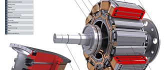
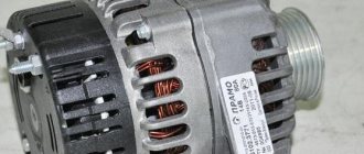
A car generator is an important element in the design of a car. Simply put, the generator, which is an electric motor, supplies the entire on-board network of the car with electricity after starting the internal combustion engine. The generator also charges the battery.
As practice shows, for one reason or another, various generator breakdowns can occur, but a fairly common malfunction is the diode bridge. Next, we will look at why diode bridges fail, the generator does not charge the battery, and also how to check the diode bridge of the generator.
What is a diode bridge and what is it for?
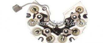
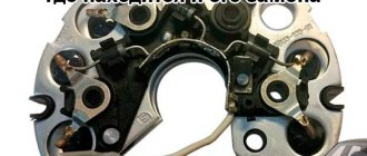
The diode bridge is installed in the VAZ generator and is designed to convert multiphase current into unidirectional pulsating current. This is one of the important elements of the generator along with brushes. Its failure causes the generator to stop charging the battery.
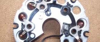
The diode bridge of the generator consists of four or six diodes. The diodes are located on the body of the generator circuit and tend to burn out, there are several reasons for this.
If the battery fails to charge, one of the reasons may be the failure of the diode bridge.
Useful tips
As practice shows, the diode bridge of the generator often burns out precisely as a result of the carelessness of the car owner himself. If there is an incorrect connection of the battery terminals, the load on the generator is prohibitively high, then the diodes burn quickly.
It is also important to understand that active use of the car, as a result of which dirt and water gets on the generator, does not add resource to the diode bridge. As a result, in order to increase service life, you need to properly wash the engine, follow the rules for connecting terminals to the battery, know how to light a car, etc.
We also recommend reading the article on how to quickly check the functionality of the generator. From this article you will learn what signs indicate that the generator is faulty, as well as how to check the generator with a multimeter without removing it.
In the case where there is no new diode bridge, then the solution is to replace the failed individual elements. To replace, you need a powerful soldering iron, as well as known-good diodes in stock.
Please note that replacing the entire diode bridge at once is also not always advisable. If the generator has been in service for a long time, then it is optimal to change the diode bridge assembly, but this will be a more expensive solution.
In cases where the generator is not old, and the breakdown occurred due to an accidental mistake by the owner (for example, after lighting the car), you can limit yourself to only repairing the generator. Often, in this case, there is no need to fear that other diodes will also begin to burn out quickly (provided that the rules are followed during further operation).
Checking with a multimeter
The method is the most labor-intensive of the three presented. The diode bridge must be completely dismantled. Each diode is then tested individually.
- The tester must be set to test mode. When two electrodes of the tester are short-circuited, it will squeak. You can set it to the 1 kOhm .
- Connect the electrodes to both ends of the diode, then swap the leads. A diode is considered to be working if it shows 400-700 ohms and infinity in the other. If you have infinity in two directions, the diode is broken . If there is resistance, but it is small or the same on both sides, the diode is broken and requires replacement.
- Broken diodes can be replaced, but it’s easier to go and buy a new one. Practice shows that soldering does not give the desired result, and ultimately, we will go for a new bridge.
Methods for diagnosing performance
To independently detect faults in the rectifier unit, you will need a multimeter (tester) or a 1–5 W, 12V lamp. The bridge is removed from the generator. It is recommended to diagnose each diode one by one.
Multimeter (tester)
Measuring DC and AC current with a multimeter will help diagnose diode failure
The tester is set in ohmmeter (1 kOm) or diode monitoring mode. One electrode is tightly fixed to the frame of the diode or the plate on which it is fixed, the second to its terminal. Then the electrodes are swapped. For a working diode, one indicator will be equal to 400–800 Ohms, depending on its power, the second will be equal to 1 (tends to infinity), which indicates a closed (locked) direction. The remaining diodes are checked in the same way.
The operating resistance on all semiconductors should not differ significantly. The permissible difference in resistance of semiconductors on one wafer is 5 units. A diode with an exceeding deviation does not work well, which will lead to charging problems.
Units on both sides indicate diode damage. When the tester produces any values when changing electrodes, the diode has a short circuit.
It is acceptable to set the multimeter to test mode, but this method is less accurate. In this case, with a correctly functioning diode in one position of the probes, the tester will emit a sound signal, and in another it will be silent. A squeak or silence on both sides when changing electrodes indicates damage to the diode.
Video verification instructions
More information about diagnostics on a VAZ (video with diagrams from a practitioner)
A light bulb
In the absence of a tester, the operating condition of the semiconductors is checked with a test lamp. Why connect the battery to the lamp and form a gap near it, the stripped ends of which will serve as probes to facilitate testing. The probes are simultaneously pressed against the body and the diode terminal, then the polarity is changed. In one position, the lamp will light for a working semiconductor, but not in another.
Circuit for checking a diode bridge using a light bulb
Checking with control
- Connect the diode bridge plate (housing) to the negative terminal of the battery, and it should be pressed tightly against the generator body.
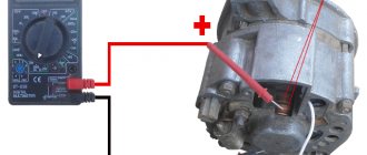
- We take the control and connect one end to the “positive” terminal of the battery, and connect the other end to the output terminal of additional diodes. After this, to the “positive” terminal bolt and to the connection points of the stator winding, we perform the actions described in the photo.
- If the light bulb is working properly, it should not light up when touched. If it does catch fire, you can safely conclude that the diode bridge is broken.
Symptoms of a problem
If even one diode breaks or breaks, a voltage with dips is formed at the generator output. The battery compensates for some of the failures, however, the voltage in the on-board network drops, which affects the performance of electrical appliances and lighting equipment. Electromagnetic interference is generated, reducing the quality of the speaker system and radio receiver.
Malfunctions of the diode bridge are determined by the following factors:
- the battery runs out quickly without being recharged from the generator (the warning lamp continues to light after starting the engine);
- the battery is recharged, the electrolyte boils;
- headlights dim when driving;
- The starter is difficult to start the engine;
- The power of the air conditioner and heater decreases;
- sounds in the audio system are distorted.
The main causes of damage to semiconductors are moisture entering the bridge through the ventilation holes of the generator during vehicle operation or mixing up the “+” and “-” wires when starting the engine from the cigarette lighter.
A malfunction of the diode bridge is not visible to the naked eye, so it is necessary to use special devices
How to Accurately Test a Diode Assembly: Detailed Analysis
To check, you will need a multimeter that has a diode test mode.
Verification steps:
- Testing begins with diodes 1 and 2. To do this, the red probe of the tester is connected to the terminal with the “-” sign. Above the two center terminals there is an AC or ̴ marking. The black probe is connected in turn, first to one such terminal, and then to the second. This is a direct connection in which current flows freely. The display of the digital multimeter will show the voltage drop across the pn junction when connected directly. In foreign datasheets this value is designated as Vf. For silicon diodes it is in the range of 0.4-0.7 V. For Schottky semiconductors it is lower and equal to approximately 0.3 V. If these values are displayed on the measuring device, then the diode assembly is working.
- To clarify the results of checking diodes 1 and 2, a reverse connection is made. To do this, connect a black probe (negative) to the “-” terminal. The red probe is alternately connected to the terminals marked AC or ̴. The display should show a unit, indicating high resistance and no reverse current. If this is so, then the serviceability of diodes 1 and 2 is confirmed.
- Next, check the verification of diodes 3 and 4 under the condition of direct connection. To do this, connect the black probe to the positive, and the red one in turn is connected to the AC terminals. The display should display the voltage drop across the pn junction, which was described in detail in the first paragraph.
- To confirm the result, connect the red probe to the plus, and the black probe to the AC terminals. The display should show one.
If the diode assembly successfully passes this test, we can say with confidence that all elements are in good working order.
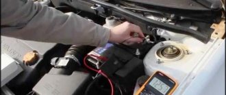
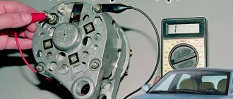
Checking the generator on the car
First of all, you need to see if the alternator belt is intact. If it is not torn, then the belt tension is checked. Then it's time for the battery. Using a tester (multimeter), we measure the voltage at the terminals. It should be around 12−12.7 volts. If everything is fine, start the engine. If the battery is discharged, charge it and start the engine again.
We measure the voltage at the battery terminals. It should be within specified limits, usually from 13.2 to 14.5 volts. But on modern cars these limits may differ. If you have an instruction manual, you can read it. Deviation from the specified values in any direction is a malfunction. These deviations can be of three types:
- Lack of charging current - the generator does not work.
- There is a charging current, but below the minimum value -
- Voltage above the maximum value means the battery is overcharged.
All three cases indicate an existing malfunction in the vehicle's electrical supply system. it is necessary to carry out a comprehensive check of the generator.
But before that, conduct a visual inspection of all the wires and cables that go from the generator to the battery. There should be no visible damage, breaks or oxidation of the electrical wiring. Be sure to check the terminals on the battery, starter and alternator. They must be clean and dry. Any oxidation, rust or dirt must be cleaned off. Often this helps restore lost contact and the car begins to work as expected. If this does not help, we proceed to a detailed check.
Using a Multimeter
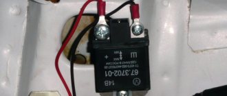
For further inspection, it is better to remove the generator from the car. First of all, remove the relay regulator from the generator and check it. To check the voltage stabilizer, you will need a multimeter and a charger with regulated voltage. It would be better to use a power supply instead of a charger. Voltage adjustment from 0 to 16 volts will be sufficient.
Connect the plus of the power supply to the regulator - usually this is a male plug connection. Hook the minus to the minus, it is usually output to the ear of the relay mount. Connect the red wire of the tester to the positive wire of the power supply, the black wire to the negative wire. Connect two stripped wires to the brushes, one for each. A light bulb is connected to the other pre-stripped ends (it can be removed from the rear lights of the car during testing). The test bench is ready.
Continuity of the relay regulator
Connect the power supply to the network, carefully use the regulator knob to begin raising the voltage. At the same time, monitor the multimeter readings. The light bulb should not light up at the very beginning, but as the voltage rises it should light up, first at half-incandescence and as the voltage increases, the brightness should increase.
When the 14.5 volt mark is reached, the regulator should operate, cutting off the voltage. The light should then go out. It is generally accepted that the stabilizer is working if it cuts off the current at values from 14.2 to 14.8 volts. If this happens at lower or higher values, then the voltage regulator is faulty. The relay is also faulty if there is no current cutoff at all.
If the relay malfunctions, replace it with a new one. If it is working properly, we continue checking.
Safety regulations
Depending on where and which diode bridge you are testing, consider the following:
- Many modern units operate with high-voltage power supplies, that is, the bridges in them are under high voltage! Therefore, before testing, disconnect the device from the network and discharge the smoothing capacitors, which are in the photo under the scarlet arrows. This is easy to do: you can short-circuit the capacitor terminals for a second with a screwdriver, while holding it by the insulating area. If you do not take this point into account, you can lose your life!
- When the repair is completed, you should not directly connect the device to the network. First, turn it on through a lamp (150-200 W). If everything is ok, it will burn a little. But a bright light indicates a short circuit.
- Take care of your eyes and more. Parts of impulse units can explode if repaired incorrectly, and this is very dangerous!
Now you know how to test a diode bridge with a multimeter. Take on the job if you have thoroughly studied safety precautions and are confident in your abilities.
Share your experience in the comments.
We wish you safe and accurate measurements!
Checking with an indicator screwdriver
This is the simplest test option, which will give a general idea of the condition of the diode bridge and the entire circuit as a whole. To operate, you only need an indicator; the entire procedure is performed under voltage, so extreme caution should be used:
- Touch the tip of the screwdriver to each AC voltage terminal of the diode bridge in turn. If the light does not light, this indicates a fault in the circuit up to the diode bridge - a broken winding, a broken charger, etc. If the light is on, then voltage is supplied to the bridge normally.
Rice. 2. Testing with an indicator screwdriver
- Also touch the positive terminal with a screwdriver - if the light comes on, then the diode bridge normally passes positive half-cycles, respectively, there is potential at this pin. If it does not light, there is damage to the diode bridge.
- Repeat the same procedure with the negative terminal. Be sure to divide the test into both terminals of the rectifier unit, since a fault may be present in any diode and in any branch.
As you can see, in this example an insulated blade screwdriver was used. This is due to the need to perform work under voltage, when you can cover different parts of the electrical installation with a metal part, which will entail extremely unpleasant consequences. A significant disadvantage of the method is its low information content and the limitation on the operating voltage - since the indicator is designed for a nominal value of 220 V, it cannot be used for low-voltage circuits.