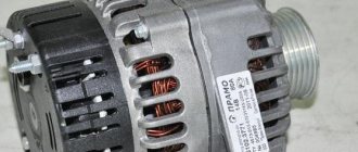
Despite the high quality of assembly and parts of the VAZ 2110, the diode bridge of the generator often fails. A bridge breakdown can be recognized by the heating of the generator of a personal vehicle in a short period of time.
This article will talk about how to diagnose and change the diode bridge on a VAZ 2110 with your own hands, without spending a lot of money.
It’s probably not worth mentioning the important role of the generator. The operation of the entire engine depends on its performance and quality.
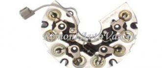
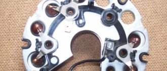
A diode bridge is an electrical device that is aimed at converting alternating current into direct current. Also, this device is also called a rectifier.
It consists of 4-6 diodes, which act as “auxiliary” gateways that pass current in one direction. The bridge prevents current from passing to the stator windings of passenger vehicles. The diodes are located on the protective box of the generator and can burn out under the influence of various factors.
Functions of the diode bridge in the VAZ 2110
Content
When the generator turns on, it begins to produce direct current. Thanks to the pulsating current, all electric batteries work and the battery is charged. However, to power the entire car, alternating current is required at a certain frequency.
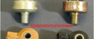
Diode bridges are unique; they have different designs.
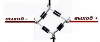
However, among the variety, a three-phase rectifier is common for the following reasons:
- The maximum constant current is created at the output;
- Three-phase devices are suitable for half bridges and diode bridges;
- Thanks to the design, a capacitor can be used to serve as a current filter.
Causes of breakdowns
As numerous checks show, the main cause of breakdowns is factory. Here, first of all, you need to pay attention to the shell in which the diodes are located. If it is aluminum, it is better not to take such a unit. Much more reliable is steel.
In addition, if the seller does not provide a guarantee, you should be wary. According to reviews on the Internet, the most unreliable diode bridges are made in Belarus.
- Another reason is moisture ingress, which results in oxidation of the space between the diode itself and the housing;
- Contact of oil or other working fluids of the VAZ 2110 on the surface;
- If you reverse the polarity of the battery while lighting or charging, the diode bridge can easily “fly out”;
- You can also suspect that the VAZ 2110’s rectifier is failing if the battery stops charging.
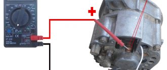
Instructions for checking the diode bridge with a multimeter
Verification steps:
- Switch the device to the desired mode and set the sound signal;
- Connect the probes of the device to the diode terminals. A central plate made of aluminum or steel is connected to the negative output. On the positive side, a metal core with a cross-section of no more than 1 millimeter;
- By touching the outputs one by one with the probes, the driver should hear a sound signal.
If the sound indicator is triggered at any position of the probe, then the bridge is broken. If absent, then there is a broken diode. There should be a signal when one side is tested.
Causes of problems
As practice shows, the main cause of problems is mainly factory. If the shell is made of aluminum, then it is better to refuse such a unit. If it is steel, then this option should be taken. It is more reliable and durable. If the seller does not provide a guarantee, then this also makes it clear that you should not trust his product.
In addition, the causes of breakdowns may be:
- moisture ingress, which causes the space between the diode and the housing to oxidize;
- ingress of oil or other liquids;
- if the polarity of the battery is reversed when lighting a cigarette.
If the diode bridge cannot be repaired, which happens if it has worn out over the years or has completely failed, then it is necessary to resort to the last resort - replacing this unit.
Checking the diode bridge with a light bulb
The second method to check the diode bridge without dismantling and independently is as follows:
Checking the diode bridge with a light bulb
- The first step is to remove the protective casing;
- You can check the operation of the diode circuit by connecting both ends of the light bulb to different poles. If current is supplied to the light bulb and it lights up, then there is a problem in the electrical circuit, most often it is a short circuit. From this it follows that the diodes are faulty. Also, it is important to understand which charge does not work: positive or negative. This will provide information about the cause of the breakdown and will become an experience for the car owner.
- The negative group is checked first. To check the charge, connect the minus of the light source to the generator housing, and the plus to one of the bolts for fastening the diode bridge. If the light bulb is receiving AC or DC current, there is a short circuit somewhere.
- The fourth step is to check the positive diodes. We also connect the negative of the light bulb to one of the fastening products, and the positive of the battery through a light bulb with a “30” generator clamp. At this stage of the problem, as in the previous case, a sign of a malfunction is the light coming on.
- The final stage will be checking additional diode bridges. We connect the negative pole of the battery to the fastener, and connect the positive pole of the battery through the lamp to the terminal of the generator “61”. You can detect the presence of a short circuit if the light comes on.
Checking the generator on the car
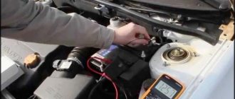
First of all, you need to see if the alternator belt is intact. If it is not torn, then the belt tension is checked. Then it's time for the battery. Using a tester (multimeter), we measure the voltage at the terminals. It should be around 12−12.7 volts. If everything is fine, start the engine. If the battery is discharged, charge it and start the engine again.
We measure the voltage at the battery terminals. It should be within specified limits, usually from 13.2 to 14.5 volts. But on modern cars these limits may differ. If you have an instruction manual, you can read it. Deviation from the specified values in any direction is a malfunction. These deviations can be of three types:
- Lack of charging current - the generator does not work.
- There is a charging current, but below the minimum value -
- Voltage above the maximum value means the battery is overcharged.
All three cases indicate an existing malfunction in the vehicle's electrical supply system. it is necessary to carry out a comprehensive check of the generator.
But before that, conduct a visual inspection of all the wires and cables that go from the generator to the battery. There should be no visible damage, breaks or oxidation of the electrical wiring. Be sure to check the terminals on the battery, starter and alternator. They must be clean and dry. Any oxidation, rust or dirt must be cleaned off. Often this helps restore lost contact and the car begins to work as expected. If this does not help, we proceed to a detailed check.
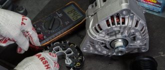
Using a Multimeter
For further inspection, it is better to remove the generator from the car. First of all, remove the relay regulator from the generator and check it. To check the voltage stabilizer, you will need a multimeter and a charger with regulated voltage. It would be better to use a power supply instead of a charger. Voltage adjustment from 0 to 16 volts will be sufficient.
Connect the plus of the power supply to the regulator - usually this is a male plug connection. Hook the minus to the minus, it is usually output to the ear of the relay mount. Connect the red wire of the tester to the positive wire of the power supply, the black wire to the negative wire. Connect two stripped wires to the brushes, one for each. A light bulb is connected to the other pre-stripped ends (it can be removed from the rear lights of the car during testing). The test bench is ready.
Continuity of the relay regulator
Connect the power supply to the network, carefully use the regulator knob to begin raising the voltage. At the same time, monitor the multimeter readings. The light bulb should not light up at the very beginning, but as the voltage rises it should light up, first at half-incandescence and as the voltage increases, the brightness should increase.
When the 14.5 volt mark is reached, the regulator should operate, cutting off the voltage. The light should then go out. It is generally accepted that the stabilizer is working if it cuts off the current at values from 14.2 to 14.8 volts. If this happens at lower or higher values, then the voltage regulator is faulty. The relay is also faulty if there is no current cutoff at all.
If the relay malfunctions, replace it with a new one. If it is working properly, we continue checking.
Replacing a diode bridge in a VAZ 2110
Replacing a diode bridge is not particularly difficult if you follow safety rules and instructions.
To perform a bridge replacement, the following is required:
- The generator is removed from the car and freed from the cover. Remove the cover by unfastening the lock on the sides. After this is done, you can start working.
- Screws or bolts are unscrewed with tools. And remove the voltage regulator.
- Next, the wire connector is disconnected from the regulator.
- Using a spanner or socket, unscrew the three bolts that secure the wires to the diode bridge, and another bolt that secures the bridge itself.
- The fifth step is to get rid of the wires. Removing and putting the wires aside so as not to get in the way.
- Using a Phillips screwdriver, you need to unscrew the screw securing the capacitor. Next you need to remove the capacitor itself from the generator and the diode bridge.
- Taking a new diode bridge, put it in place of the old one and screw it on, not forgetting about the capacitor. The entire installation of a new device occurs in the reverse order.
This completes the replacement of the diode bridge on the VAZ 2110. The replacement procedure itself will not take much time and will save money that would have been spent not only on a new car device, but also installation in a car service center. The whole operation is simple, even a beginner can do it. The main thing is not to forget to diagnose every part of the car and treat it with care.
How to test a generator with a multimeter
The diode bridge of the generator can be checked with a multimeter, but you can also use the stand that was used to check the regulator.
But before that, first of all, without removing the rectifier bridge from the generator, connect the red wire of the tester to terminal 30 of the generator, and the black wire to the housing. Set the tester operating mode to dial (diode icon). If it is not there, then set it to 1-2 kOhm. The multimeter should show infinity. If the readings are different, the diode bridge is faulty.
Then check the current rectifiers for breakdown. Leave the positive (red) probe on terminal 30, touch the negative one to the bridge mounting bolts one by one. The multimeter display should show infinity in all cases; any others mean a breakdown.
Additional testing of generator components faults
The stable operation of this device can be affected not only by the DM and the relay regulator, but also by the electric rotor and stator windings, brushes and capacitor. If the first measurements do not reveal any malfunctions in the operation of the main generator components, then proceed to additional testing of the generator components.
Generator winding testing
This type of measurement is carried out on a dismantled and disassembled generator. You will need to separately check the serviceability of the rotor and stator windings. The meter is set to ohmmeter mode at a value of 200 Ohm.
The main stages of monitoring the electric rotor and stator windings:
- Measure the resistance value on the rotor windings. For this purpose, probes are connected to the outputs of the windings. The normal value is above 5 ohms, if less than 1.9 ohms, there is a turn short on the rotor. Most often, the electrical circuit breaks in the connection areas between the rotor winding and the ring. It is possible to determine the malfunction by moving the wire in the soldering area with a probe. Alternatively, integrity may be compromised here.
- Carefully inspect all connections. It is possible that dark and damaged wire insulation will be detected, which is a consequence of a break and short circuit.
- We call electrical circuits to determine the short circuit on the housing. To do this, the first probe is brought to the rotor shaft, and the second to any ring. If the winding is working properly, the ohmmeter reading will go off scale. If the resistance is low, this winding must be rewound. In this case, perfect balancing must be maintained.
- Before checking the stator, a visual inspection is performed, paying attention to all kinds of external damage to both the housing and the insulator, as well as the places where the wires from the short circuit are burned.
- If a defect is detected, the stator is sent for rewinding.
- If no external abnormalities are found on the stator, examine it with a multimeter.
- The stator must be disconnected from the generator and removed.
- The multimeter is set to resistance control mode. Initially, the probes are installed on the 1st pair of terminals. Then they test a pair of windings “1–3”, and then “3–2”. If the analog multimeter needle goes off the scale, the windings will need to be rewinded.
- To check the generator for the absence of a short circuit between the turns and on the housing. The first probe is connected to the terminal, and the second to the body. If the windings are short-circuited, the multimeter on the scale will show a lower resistance value than on the working ones.
Diagnostics
The diagnostic procedure must be carried out on a dismantled generator device, so the unit must first be removed. When the mechanism is dismantled, the plastic cover is removed from it, as mentioned above, the DM is located immediately behind it (the author of the video about self-diagnosis with a multimeter is Ramil Abdullin).
For diagnostics you will need a tester - a multimeter - the test is carried out as follows:
- First, the multimeter should be activated in ohmmeter mode. Having done this, the positive probe of the tester must be connected to the diode bus.
- In the same way, connect the negative probe of the tester to the corresponding contact on the diode bridge.
- Next, you need to monitor the tester readings. If the diode bridge is in working condition, then the tester display will show values close to infinity. If there are no such values, then most likely the DM is inoperative and should be replaced. But the diagnosis does not end there.
- Next, you will need to swap the location of the probes, that is, the negative contact is connected to the positive one and vice versa. Having done this, again look at the multimeter reading on the display. If there are no failures in the operation of the DM and the device as a whole is functioning normally, then a value of several hundred Ohms should appear on the tester screen.
- If the DM is equipped with an additional diode, then you can check it too. In this case, the diagnostic procedure is performed in a similar way; you just need to repeat all the steps.
Photo gallery “Self performance test”
Possible malfunctions: signs and causes
As stated above, the purpose of diode elements is to convert alternating voltage to direct voltage. If one of the diode elements fails, then its malfunction may be indicated by such a sign as a decrease in the voltage level, as well as power in the vehicle electrical network.
For what reasons may problems occur in the operation of the DM:
- Manufacturing defects. As practice shows, many modern DM manufacturers use aluminum shells of fairly low quality in their production. Accordingly, this affects their reliability as a whole. That is why it is recommended to use DM equipped with steel shells, since this directly affects the service life.
- Moisture gets inside the device. Regular exposure to moisture can cause oxidation, in particular, on the surface between the device body and diode elements.
- Engine fluid getting into the unit is one of the most common causes. Exposure to lubricant can lead to disruption of the functionality of the device as a whole, especially if it gets inside the generator unit, directly on the DM.
- Another reason why DMs on “tens” often fail is the polarity of the battery is reversed. If you connect the battery to a charger or accidentally reverse the polarity while “lighting up” the car, this will most likely cause the motor to burn out. Therefore, you should always remember that plus is connected to plus, and minus is connected to minus.
- Regular operation of a vehicle with a weak battery. If the battery does not pull the load and constantly operates under conditions of reduced charge, then the reason may be the inoperability of the DM.
Replacement
When dealing with any component related to electrical equipment, you need to start by de-energizing the VAZ 2110. So, we proceed according to the algorithm:
- Disconnecting the battery (remove the “-” terminal);
- Remove the pink wire that turns on the generator. To do this, you need to unscrew the nut from the positive bolt;
- Loosen the upper and lower nuts, and also unscrew the tension bolt, remove the belt;
- Turn the generator 90° and remove the lower mounting bolt;
- Clean all connections, as well as the rectifier housing itself;
- Clean the inside of the ring very thoroughly;
- Replace the generator diode bridge with a new one;
- Reassemble all parts;
- Check the functionality of the generator.
Relay regulator
The relay regulator maintains the optimal voltage value in the standard electrical circuit. In fact, it is precisely this that prevents the voltage from increasing to critical values. To carry out the test, start the engine, connect the multimeter and set the “voltage measurement” value.
After this, it is necessary to measure the power supply of the on-board network directly at the battery terminals or at the contacts of the generator itself. The values should be between 14–14.2 V.
Then you need to press the accelerator and take the measurement again.
Note! The readings should not change by more than 0.5 V. Otherwise, this will indicate incorrect operation.
Design
In the original (factory) configuration, the diode bridge of the generator on the VAZ 2110 is a monolithic structure. It is quite reliable, inexpensive, compact, and has, one might say, only one drawback: if one of the diodes burns out, its local replacement is impossible; you need to buy a new factory bridge and install it.
In the event that a check shows that the diode bridge is no longer functioning and needs to be replaced, it is quite possible to assemble it from various diodes. If the factory layout provides four or six diodes, then during self-assembly you can install an additional one.
Many car enthusiasts do this. In addition, as a rule, in the case of self-assembly, diodes are installed not in the factory layout, but a little stronger, so that they do not burn out so quickly.
But since it is impossible to qualitatively test such a rectifier, during “home assembly” you can damage the generator, after which it will be necessary to replace not just a cheap part, but the entire assembly.
Selection of diodes for the rectifier bridge
The main thing they look at when choosing a diode is power. It depends on the highest rated current generated by the generator. The higher the generator power, the more powerful the diodes. Diodes for the rectifier bridge are conventionally divided into categories: low power diodes, current 300 mA;
medium power diodes, current 300mA – 10 A;
high power diodes above 10 A.
Diodes are divided according to the type of material used, these are germanium and silicon. Most manufacturers prefer silicon diodes. The main reasons for choosing silicon diodes:
· low reverse current;
· high permissible reverse voltage up to 1500 V;
·operability of silicon diodes from -60 to +150оС
Germanium diodes have a low reverse voltage value of up to 400V. They operate in the temperature range from -60 to +85°C.
For example, to replace diodes for a Bosch generator with a 140A for a Touring Custom car. For such a generator you need 50A diodes, for example, Cargo 50A 138634 and Cargo 138635, for a 140A generator you will need 12 pieces, for an 80A generator 6 pieces.
Symptoms of malfunction
The following signs may indicate a generator malfunction:
- the warning light on the dashboard is constantly on;
- The battery began to discharge quickly, and recharging does not save the situation;
- there are malfunctions in the functioning of electrical equipment (ventilation and heating, multimedia devices, alarm system and lighting), even if the motor is working properly;
- there was a smell of something burnt in the car interior;
- the generator began to whistle or rustle.
Read also: DIY wooden mechanisms
If you notice these symptoms, you should immediately go to a car service center for a thorough diagnosis. However, you can check the functionality of the generator on your own, especially if you have the skills to use an autotester.
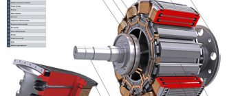
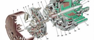
Generator rotor
The rotor is a rod made of metal with an excitation winding. If you look at one of its ends, you can see special contact rings with sliding brushes.
First of all, it is necessary to remove the rod and conduct an external inspection of the winding, as well as the bearings. In some cases, the problem is damage. If everything is in order, then you should proceed to checking with a multimeter.
The device should be set to “Resistance measurement” mode. It should be checked between the slip rings. This value should not be too large - this indicates the serviceability and integrity of the winding.
Note! It is quite difficult to carry out detailed diagnostics of the rotor on your own, so if you suspect any problems, you should contact a car repair shop.