VAZ-2112 wiring diagram
Wiring diagram for a car in a hatchback body (click on the picture to enlarge)
Designations: 1 – Headlight, 2 – Horn, 3 – Main radiator fan, 4 – Starter, 5 – Battery, 6 – Generator, 7 – Gearbox limit switch (reverse), 8 – Actuator in the front passenger door, 9 – Relay power windows permissions, 10 – Starter relay, 11 – Heater fan, 12 – Electric heater partition drive, 13 – Main pump, 14 – Washer reservoir sensor, 15 – Driver’s door actuator, 16 – Front passenger window selector, 17 – Fifth wheel release button doors, 18 – Heater fan resistance unit, 19 – Main wiper motor, 20 – Driver's window lift selector, 21 – Front passenger's window lift motor, 22 – Central locking, 23 – Exterior light switch, 24 – Brake fluid leakage sensor, 25 – Additional pump , 26 – Driver's window lift motor, 27 – PTF on indicator, 28 – PTF switch, 29 – Dashboard , 30 – Heated glass on indicator, 31 – Heated glass switch, 32 – Steering column selector switch, 33 – PTF relay, 34 – Ignition switch , 35 – Main fuse block, 36 – Illumination of heater controls, 37 – Hazard warning button, 38 – Heater control controller, 39 – Glove compartment lighting, 40 – Glove compartment lid end cap, 41 – Cigarette lighter, 42 – BSK – display unit, 43 – Ashtray illumination, 44 – 12V socket, 45 – Instrument lighting switch, 46 – Actuator in the right rear door, 47 – Right rear passenger window selector, 48 – Clock, 49 – Right rear passenger window motor, 50 – Brake limit switch (closed – pedal is pressed), 51 – Left rear passenger window motor, 52 – Left rear passenger window selector, 53 – Actuator in the left rear door, 54 – Turn signal, 55 – Handbrake limit switch (closed – handbrake on), 56 – Rear wiper motor, 57 – Navigator’s lamp, 58 – Interior lamp, 59 – Temperature sensor in the heater, 60 – Limit switch for an open front door, 61 – Limit switch for an open rear door, 62 – Trunk lighting, 63 – Rear optics (on the body), 64 – Rear optics ( on the fifth door), 65 – License plate illumination.
The letters indicate the terminals to which it is connected: A – Front speaker on the right, B – Radio, C – Injector harness, D – ESD diagnostic connector, D – Front left speaker, E – Diagnostic connector for the heater controller, G – Rear right speaker, W – Rear left speaker, I – BC connector, K – glass heater thread, L – fifth door actuator, M – Additional brake light.
All door switches remain open when the doors are closed. We provide a wiring diagram for the VAZ-2112 with a description, and information about the limit switches will be useful to signal installers.
Please note that starter power may be connected in different ways. Either the current to terminal 50 comes directly from the lock, or through relay 10. The second option (as in the diagram) is less common.
The three relays shown in the diagram are always installed on a block mounted on top of block 35 (see photo).
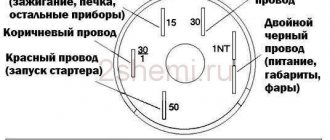
Main fuse and relay box
Here part 5 is “relay 9”, and part 7 is “relay 10”.
Window lifters
When the ignition is turned on, relay 11 closes its contacts. This enables the operation of the power windows controlled by selectors 3, 4, 9 and 10.
Without the ignition, the power windows don't work.
The diagram does not require any other explanation.
central locking
The diagram shows four actuators, as well as control unit 3. Actuator 7 is located in the driver's door.
Actuators, central locking unit and one limit switch
It would seem that everything is simple here. But in the description of the VAZ-2112 electrical circuit, the main thing is usually not reported: the white cord is the input for the “Open” command, the brown one is the “Close” command.
There is a variant of the circuit where module 7 contains only a limit switch (without an actuator).
Relay K4 turns on the low beam lamps, K5 - high beam.
Headlights with single-filament lamps
Selector lever 3 only switches on relay K5. But in the explanation to the electrical diagram on the VAZ-2112 it is said that:
- Selector 3 is used to select the “near/far” mode;
- With its help, the high beam lamps are turned on briefly.
Basic principles
It doesn’t matter what kind of engine the Lada is equipped with - it could be a VAZ 2110 injector or a 2110 carburetor - the basic electrical components in this model will not be different. Below are the main features that the VAZ 2110 wiring has:
Below are the main features that the VAZ 2110 wiring has:
- Any electrical equipment, as well as devices that are powered by electricity, is based on a single-wire connection. Lada engineers equipped the electrical wiring with wires of different colors, and each of them is responsible for the operation of certain functions. Accordingly, certain devices will be connected to the circuit through a specific wiring harness. Thanks to this, the car enthusiast has the opportunity to understand the nuances of the wiring himself, especially since, if necessary, he himself will be able to repair certain elements.
- The VAZ 21102 has 8 or 16 valves, it makes no difference, the minus is the ground, that is, it is connected to the vehicle body.
- As for the positive cable, on an 8- or 16-valve engine it will always be red. So, if the VAZ 2110 wiring is being replaced or repaired, there is no need to change the color of the wires, otherwise you will confuse yourself in the future.
- Each equipment or system associated with the vehicle’s electrical circuit is equipped with a separate cable harness.
- The tenth model of the VAZ family is designed in such a way that when the battery is activated, the entire electrical circuit and equipment operate under voltage. Therefore, when performing any work related to the on-board network, you should always disconnect the battery.
- Remember that there is also a contactless system. As a rule, it is necessary in order to create a high-quality spark when starting the engine, which also contributes to better combustion of the combustible mixture. For the normal functioning of such a contactless system, it is necessary to use high-voltage cables (the author of the video is MR. BORODA).
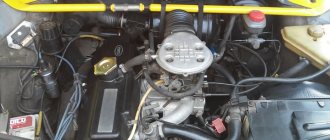
Carburetor models
The first models of 8- and 16-valve VAZ 2110 cars were equipped only with carburetor engines. A few years later, the domestic automobile concern began to equip its vehicles with injection engines. Of course, the injection model is more advanced, but today in Russia and the CIS countries tens of thousands of carburetor cars with 8- and 16-valve internal combustion engines are used.
Most likely, dozens of owners are interested in the question: is the circuit different on carburetors and injectors 21102 or not? In principle, there are no special differences between these versions in terms of the electrical circuit. Almost all systems used on injection 8- and 16-valve engines are identical to carburetor units. Accordingly, if you need to replace a carburetor engine with an injection one or install additional devices, then there will be no problems with this. If you look into the engine compartment, you will notice that both versions of the car even have the same outputs and plugs.
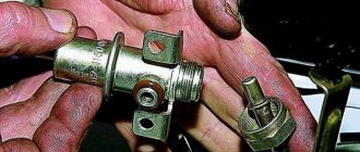
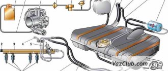
One of the main points that must be taken into account when replacing a carburetor with an injector is the connection of the fuel pump. In order for the fuel pump to always work correctly, it is necessary to additionally install wiring to power it to the control unit.
Injector
In addition to the fact that the electrical wiring in the carburetor and injection versions is virtually identical, the injector has certain features. For example, it is equipped with fuses, and also in the injection versions of the car there are a larger number of sensors.
In fact, as a result of the fact that these vehicles are equipped with a large number of different sensors designed to provide ECU functionality, the system itself is more complex. It should be noted that carburetor versions do not have an electronic control unit. To repair the system if necessary, you need to clearly know about all its components and their installation locations. The electrical circuit itself in any car is divided into the engine compartment and the interior. Above you can familiarize yourself with the electrical circuit diagram, and below are its main symbols.
Ignition and engine control circuit
Here are the control diagrams for the following internal combustion engines:
- 21120 – January 5.1 or BOSCH M1.5.4N, Euro-2;
| Motor | 21120 (Euro-2) | 21124 (Euro-2) | 21124 (Euro-3) |
| Injectors | 1 | 2 | 2 |
| Ignition coil | — | 1 | 1 |
| Candles | 2 | — | — |
| Ignition module | 3 | — | — |
| Diagnostic connector | 4 | B | B |
| ECU | 5 | 3 | 3 |
| Tidy taps | 6 | E | E |
| Ignition relay (6) | 7 | 4 | 4 |
| Ignition fuse (1) | 8 | 5 | 5 |
| Fan relay (4) | 9 | 6 | 6 |
| Fan fuse (2) | 10 | 7 | 7 |
| Fuel pump relay (5) | 11 | 8 | 8 |
| Fuel pump fuse (3) | 12 | 9 | 9 |
| Mass air flow sensor | 13 | 10 | 10 |
| Rough road sensor | — | — | 11 |
| TPDZ | 14 | 11 | 12 |
| DTOZH | 15 | 12 | 13 |
| RXX | 16 | 17 | 14 |
| Lambda probe main | 17 | 14 | 15 |
| Additional lambda probe | — | — | 16 |
| Knock sensor | 18 | 15 | 18 |
| DPKV | 19 | 16 | 19 |
| Canister purge valve | 20 | 13 | 17 |
| APS block | 21 | 18 | 20 |
| APS indicator | 22 | 19 | 21 |
| Speed sensor | 23 | 21 | 23 |
| Fuel pump + level sensor | 24 | 22 | 24 |
| Oil pressure sensor | 25 | 23 | 25 |
| Antifreeze thermometer sensor | 26 | 24 | 26 |
| Oil level sensor | 27 | — | — |
| Phase sensor | 28 | 20 | 22 |
| ABS connector | A | A | A |
| Air conditioner connector | B | IN | IN |
| Fan connector | C | — | — |
| Illumination of the ignition switch (to the blue-white wire) | D+E | — | — |
| Bends to the door harness | — | D | D |
| + battery | F | G | G |
| Weight | G1+G2 | G1+G2 | G1+G2 |
The elements installed in the additional mounting block are indicated in brackets.
Mounting block on the right side under the dashboard
Source
Injection "ten"
In addition to the wiring that is provided for the VAZ 2110 - carburetor, "ten" - injector, it is also equipped with a number of fuses that protect almost all of it from the possibility of short circuiting.
Structurally, fuses are not provided only for the electrical supply via a relay wire from the battery, in the car starting and ignition circuit, as well as for the wire going to the generator.
Electrical circuit of an injection car
In addition, the injector (as opposed to the carburetor) is a more complex system, and in order to repair it yourself, you need to understand it well. The controller in this wiring system “reads” the operation of all systems, thereby determining and setting many indicators - calculation of the fuel mixture, etc.
VAZ-2112 diagram
The VAZ-2112 car was produced at AvtoVAZ from 1998 to 2009, in Ukraine from 2009 to 2014. The following are color wiring diagrams (injector and carburetor) with a description of all elements for various modifications. The information is intended for self-repair of cars. Electrical circuits are divided into several blocks for ease of viewing via a computer or smartphone; there are also circuits in the form of a single picture with a description of the elements - for printing on a printer in one sheet.
To diagnose and repair yourself, first look to see if everything is okay with the generator. Is it put on well and does not sag? This procedure must be done with all versions of the fuel system, both carburetor and injection. We check the fuses according to the electrical diagram. The reverse side of the safety block cover will also be of great help. There are clues there that the diagram will help you decipher. Replace the burnt out element and try to start the car again. You need to check whether the battery terminals are tightly connected and whether they are oxidized. Is the wire going from the battery to the generator and to the starter damaged?
General information
The car and electricity are fused together from the very beginning. You may recall that the very first such vehicle used an electric motor, until the internal combustion engine was invented.
Wiring a VAZ 2112 makes it possible to perform actions that simply cannot be carried out without electricity.
Among them are:
- ignition of the fuel mixture in the cylinders of a carburetor and injection engine;
- starting the engine;
- operation of head lighting devices at night to illuminate the road surface;
- fog lights when driving in conditions of limited visibility;
- light indication of the instrument scale;
- side lights for vehicle detection at night;
- turn indicators;
- signaling devices.
Schematic diagram of the electrical wiring of a VAZ 2112 car (16 valve) In addition, the wiring diagram of the VAZ 2112 will help you figure out how and what the auxiliary equipment is connected to:
- “wipers”, which allow the driver to feel normal in rainy or snowy weather;
- sound signals in case of an emergency;
- searching for a spark in case of engine failure;
- CD player and radio;
- window lifters;
- windshield and rear window heaters;
- interior lighting lamps.
The electrical wiring of the VAZ 2112 connects electrical appliances and devices with current sources located in the car. An electrical equipment system is a collection of current consumers and its producers.
Serviced battery
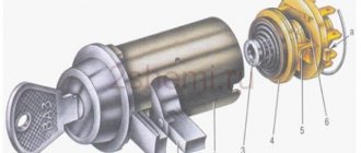
Car power supplies and ignition
Let's take a closer look at it, starting with the most important elements:
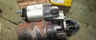
A rechargeable battery is a chemical source of energy, which is a lead-acid DC battery module. The photo shows a battery being serviced. Usually there are six of them.
It is used for:
- starting the engine with an electric starter;
- supplying power to electrical equipment when the engine is not running or when it is running at low crankshaft speeds.
Generator. Used as the main source of current for all electronic and electrical devices and instruments in the car. But, it can provide this only at medium or high crankshaft speeds. The price of this equipment depends on the manufacturer.
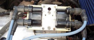
Ignition system. Designed to ignite fuel in engine cylinders. Can be contact or non-contact. Modern VAZ 2112 cars are equipped with the latter version, which has a number of advantages over the contact system, which is already considered obsolete.
The main advantages should be noted:
- increased voltage potential supplied to the secondary winding of the ignition coil;
- increased power and longer spark discharge duration;
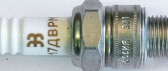
- increased service life of the spark plug;
- the breaker contacts practically do not fail;
- fuel burns better in the cylinders, which saves money as a result;
- makes engine starting easier;
- the engine becomes more responsive and more economical.
Starter relay installation diagram
If the battery is not charging
When the battery is no longer charged, it does not allow the car to be used for a long time. Maximum until it is completely discharged. In this case, a red light comes on on the instrument panel, which signals that the wiring on the VAZ 2112 requires checking.
The instructions below will help with this:
- Check the generator drive belt, it should be intact and have the required tension.
Advice: it is not recommended to apply too much tension; it will significantly shorten the life of the belt.
- If everything is fine, check the fuse. The VAZ 2112 wiring diagram for 8 or 16 valves, as well as the reverse side of the mounting block cover, will help you find out where it is located. After replacing it and starting the engine, the lamp should go out, allowing you to continue your journey.
Checking and replacing the fuse
- When the charging lamp does not go out, check the wire from the generator to the “+” terminal of the battery. There are usually two of them:
- thick – from the battery to the starter,
- thin - to the generator.
Advice: when driving only on battery power, to reduce on-board electricity consumption, turn off as many devices as possible - radio, heater fan, etc.
Modifications of the VAZ-2112 car
VAZ-21120 . Modification with a 16-valve injection engine with a volume of 1.5 liters and a power of 93 horsepower. 14-inch wheels were installed on the car. This modification has a problem with valves bending when the timing belt breaks. The problem can be solved by increasing the depth of the grooves in the piston bottoms.
VAZ-21121 . The car was equipped with a VAZ-21114 8-valve injection engine with a volume of 1.6 liters and a power of 81 horsepower.
VAZ-21122 . Budget modification with an 8-valve injection engine VAZ-2111. The car was produced without electric windows, the wheels were 13 inches in size, and the brakes were unventilated from a VAZ-2108 car.
VAZ-21123 Coupe . Three-door, five-seater hatchback. The only two doors for entering the car are 200 millimeters wider than those of the five-door hatchback, and they are mounted on new, durable hinges. The rear arches of the car have become wider. The engine was installed with a 16-valve injection engine with a volume of 1.6 liters and a power of 90 horsepower. The car was produced from 2002 to 2006 in small quantities, the reason for this was the high cost of the car.
VAZ-21124 . Modification with a 16-valve injection engine VAZ-21124 with a volume of 1.6 liters. Produced from 2004 to 2008. For this type of engine, the problem with valve bending was solved. To do this, the depth of the grooves in the piston heads was increased (up to 6.5 mm). In addition, the design of the cylinder block was changed to achieve a working volume of 1.6 liters, for which its height was increased by 2.3 mm, and the radius of the crankshaft was increased by 2.3 mm accordingly. There were also a number of other minor changes.
VAZ-21128 . The luxury version of the car, produced by Super-auto JSC, was equipped with a 16-valve VAZ-21128 engine with a volume of 1.8 liters and a power of 105 horsepower.
VAZ-2112-37 . A racing modification of the VAZ-2112, prepared for the “ring” in the Lada Cup qualifying group. The car was equipped with a 1.5-liter VAZ-2112 engine with a power of 100 horsepower. The racing car was equipped with a safety cage, an external aerodynamic kit and a front extension of the strut support cups.
VAZ-2112-90 Tarzan . All-wheel drive modification with a VAZ-2112 body on a frame chassis with transmission and suspension parts from a VAZ-21213 Niva. It was also equipped with a 1.7 or 1.8 liter engine from the Niva.
Video “How to repair wiring yourself”
Find out more about how electrical circuit repair is carried out in a garage from the video below (video author - Ramanych).
Wiring in a car plays one of the most significant roles, since it is actually the connecting link of many functional elements of the car. In the VAZ 2110, wiring is replaced if it malfunctions, or if the owner decides to upgrade. This, in turn, will help to significantly improve the efficiency of the vehicle's electronic systems. Often, old wiring simply cannot withstand the load of various additional high-tech devices. Replacing the wiring in a VAZ 2110 can be easily done on your own.
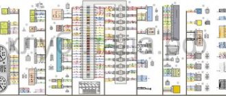
Electrical diagram of VAZ-2112
Designations: 1 – Headlight, 2 – Klaxon, 3 – Main radiator fan, 4 – Starter, 5 – Battery, 6 – Generator 2112, 7 – Gearbox limit switch (reverse), 8 – Actuator in the front passenger door, 9 – Power window enable relay, 10 – Starter relay, 11 – Heater fan, 12 – Electric heater partition drive, 13 – Main pump, 14 – Washer reservoir sensor, 15 – Driver’s door actuator, 16 – Front passenger window selector, 17 – Unlock button fifth door, 18 – Heater fan resistance unit, 19 – Main wiper motor, 20 – Driver’s window lift selector, 21 – Front passenger’s window lift motor, 22 – Central locking, 23 – Exterior light switch, 24 – Brake fluid leakage sensor, 25 – Pump additional, 26 – Driver's window lift motor, 27 – PTF on indicator, 28 – PTF switch, 29 – Dashboard, 30 – Heated glass on indicator, 31 – Heated glass switch, 32 – Steering column selector switch, 33 – PTF relay, 34 – Ignition switch, 35 – Main fuse block, 36 – Illumination of heater controls, 37 – Hazard warning button, 38 – Heater control controller, 39 – Glove compartment lighting, 40 – Glove compartment lid end cap, 41 – Cigarette lighter, 42 – BSK – display unit, 43 – Ashtray illumination, 44 – 12V socket, 45 – Instrument lighting switch, 46 – Actuator in the right rear door, 47 – Right rear passenger window selector, 48 – Clock, 49 – Right rear passenger window motor, 50 – Brake limit switch (closed – pedal is pressed), 51 – Left rear passenger window motor, 52 – Left rear passenger window selector, 53 – Actuator in the left rear door, 54 – Turn signal, 55 – Handbrake limit switch (closed – handbrake on), 56 – Rear wiper motor , 57 – Navigator's lamp, 58 – Interior lamp, 59 – Temperature sensor in the heater, 60 – Limit switch for the open front door, 61 – Limit switch for the open rear door, 62 – Trunk light, 63 – Rear optics (on the body), 64 – Rear optics (on the fifth door), 65 – License plate illumination.
The letters indicate the terminals to which it is connected: A – Front speaker on the right, B – Radio, C – Injector harness, D – ESD diagnostic connector, D – Front left speaker, E – Diagnostic connector for the heater controller, G – Rear right speaker, W – Rear left speaker, I – BC connector, K – glass heater thread, L – fifth door actuator, M – Additional brake light.
Wiring diagram VAZ-2112 injector 16 valves - full view
Latest publications
The interior heater of the VAZ-2110 (Heater), in comparison with previously produced car models of this car plant, has become a structurally more complex device. In his circuit, the valve that shuts off the supply of coolant to the heater radiator has disappeared, so it is constantly hot. The radiator is located horizontally and to remove air or steam from it, there is a steam outlet in its left tank. The air flow is controlled by two dampers driven by a micro motor. The entire work process is controlled by an electronic unit, which receives information from a temperature sensor installed next to the interior lighting lamp.
If we look at the statistics, the most likely causes of malfunctions in the stove on the VAZ 2110 can be: control unit, micro motor, fan, cabin temperature sensor, heater dampers. It was in this sequence that the stove malfunctions were located, after a survey of VAZ-2110 car owners.
Most car owners can only check if the control unit is faulty by replacing it with a known-good unit. At the same time, they should know that the “tens” that are currently in use can have four types of control units. Their markings are as follows: 1303.3854, 1313.3854, 1333.3854, 1323.3854. The first three blocks are interchangeable and can be installed on heaters 2110-8101012 and 2110-8101012-01. But the latest control unit began to be installed in 2003 on the stove 2111-8101012
That is, now, if you paid attention to the markings, on the “tens” there is a stove from a VAZ-2111.
The cabin temperature sensor is not difficult to get from the installation site. There is a mini fan on it and if you put the control unit in the “MIN” (blue dot) or “MAX” (red dot) position, it should not rotate. You can also check the functionality of the stove by replacing it with a working sensor.
Other faults may be located only inside the heater and cannot be eliminated without partial or complete disassembly. This applies to the micro motor and its shaft position sensor, as well as two dampers that distribute the flow of cold and warm air. In addition, AVTOVAZ does not recommend repairing the heater yourself. Well, you probably already know about such malfunctions of the cooling system as insufficient antifreeze level or failure of the thermostat, which affect the operation of the stove.
Sources
- https://gold.doitwork.ru/skachat-ventiljator-pechki-vaz-2112-novogo-obraztsa.html
- https://helping-auto.ru/vaz/2110/pochemu-ne-rabotaet-pechka-na-vaz-2110/
VAZ-21124 engine control circuit
Connection diagram of the VAZ-21124 engine control system with distributed fuel injection to Euro-2 emission standards (controller M7.9.7): 1 - ignition coils; 2 — nozzles; 3 - controller; 4 - main relay; 5 - fuse connected to the main relay; 6 — cooling system electric fan relay; 7 - fuse connected to the cooling system electric fan relay; 8 - electric fuel pump relay; 9 - fuse connected to the electric fuel pump relay; 10 — mass flow and air temperature sensor; 11 — throttle position sensor; 12 — coolant temperature sensor; 13 — solenoid valve for purge of the adsorber; 14 — oxygen sensor; 15 — knock sensor; 16 — crankshaft position sensor; 17 — idle speed regulator; 18 — immobilizer control unit; 19 — immobilizer status indicator; 20 - phase sensor; 21 — vehicle speed sensor; 22 — electric fuel pump module with fuel level sensor; 23 — oil pressure warning lamp sensor; 24 — coolant temperature indicator sensor; A - block connected to the wiring harness of the ABS cabin group; B — diagnostic block; B - block connected to the air conditioner wiring harness; G - to the “+” terminal of the battery; D — to the side door wiring harness block; E - block connected to the instrument panel wiring harness; G1, G2 - grounding points; I - the order of conditional numbering of plugs in the block of the immobilizer control unit; II - the order of conditional numbering of contacts in the diagnostic block.
Connection diagram of the VAZ-21124 engine control system with distributed fuel injection under Euro-3 toxicity standards (controller M7.9.7): 1 - ignition coils; 2 — nozzles; 3 - controller; 4 - main relay; 5 - fuse connected to the main relay; 6 — cooling system electric fan relay; 7 - fuse connected to the cooling system electric fan relay; 8 - electric fuel pump relay; 9 - fuse connected to the electric fuel pump relay; 10 — mass flow and air temperature sensor; 11 — rough road sensor; 12 — throttle position sensor; 13 — coolant temperature sensor; 14 — idle speed regulator; 15 — control oxygen sensor; 16 — diagnostic oxygen sensor; 17 — solenoid valve for purge of the adsorber; 18 — knock sensor; 19 — crankshaft position sensor; 20 — immobilizer control unit; 21 — immobilizer status indicator; 22 - phase sensor; 23 — vehicle speed sensor; 24 — electric fuel pump module with fuel level sensor; 25 — oil pressure warning lamp sensor; 26 — coolant temperature indicator sensor; A - block connected to the wiring harness of the ABS cabin group; B — diagnostic block; B - block connected to the air conditioner wiring harness; G - to the “+” terminal of the battery; D — to the side door wiring harness block; E - block connected to the instrument panel wiring harness; G1, G2 - grounding points; I - the order of conditional numbering of plugs in the block of the immobilizer control unit; II - the order of conditional numbering of contacts in the diagnostic block.
Basic principles
Regardless of whether your VAZ 2110 has a carburetor or an injector, the basic principles for laying the wiring are the same. Finding a wiring diagram is not at all difficult, the main thing is to understand it. Actually, according to the location, the wiring is under the hood and in the cabin.
Its basic principles are the same, and boil down to the following:
- Whatever electrical device you have in a car, its connection will be single-wire. Moreover, the creators of the VAZ 2110 from the very beginning provided that both in the diagrams in the instruction manual and in reality, the colors of the wires would be clearly distributed. Simply put, all electrical equipment is connected using wires of a clearly defined color. Each unit has its own wiring harness enclosed in blocks. Naturally, this was done so that it would be easier for those who do the repairs themselves to understand this intricacy. Thus, replacing the wiring under the hood becomes more understandable. Advice: if you have a small problem with specific equipment and only one wire needs to be replaced, it is better not to be greedy and not change it to the first one you come across. Buy a complete harness and replace it with the wire of the desired color - it will be easier for you later;
- the wire supplying power to the positive terminal of the battery is always braided in red; it is also advisable not to change its color. In all diagrams it is designated as “P”, that is, plus;
- but the role of the “minus” (in other words, mass) is assigned to the automobile body;
- all terminals of any electrical consumers are directly connected to the body;
- Each system that is electrically connected has its own wiring harness.
In the VAZ 2110, if the battery is connected, all electrical equipment is energized. That is why, in fact, before starting any repair (especially if it is related to the electrical part of the car), it is strongly recommended to disconnect the battery.
VAZ-2112 harness diagrams
Instrument panel harness diagram
1, 2, 3, 4 – instrument panel harness pads to the front harness; 5 — block of the instrument panel harness to the side door harness; 6, 7, 8 — instrument panel harness pads to the rear harness; 9 – rear window heating switch; 10 – light signaling switch; 11 – windshield wiper switch; 12 – block of the instrument panel harness to the radio; 13 – mounting block; 14 — instrument cluster; 15 – heater control controller; 16 – heater motor switch; 17 — block of the instrument panel harness to the ignition system harness; 18, 19 — blocks of the instrument panel harness to the air supply box harness; 20 — ignition switch; 21 – fog lamp relay; 22 – sound signal relay; 23 — power window relay; 24 — starter relay; 25 – seat heating relay; 26 – external lighting switch; 27 – fog lamp switch; 28 – cigarette lighter; 29 – lampshade lighting of the glove box; 30 – glove box lighting switch; 31 – switch for rear fog lights; 32 – right steering column switch; 33 – socket for connecting a portable lamp; 34 — instrument lighting switch; 35 – brake signal switch; 36 – sound signal switch; 37 – alarm switch; 38 – air distribution drive gearmotor; 39 – VAZ-2112 illuminator; 40 — instrument panel harness block to the front harness; 41 – trunk lock drive switch; 42 – rear fog light relay.
A – grounding point of the instrument panel harness.
Source
Replacing the wiring harness in the rear of the car
The vehicle manual warns that harsh climatic operating conditions have a negative impact on the vehicle's electrical components. And electrical connectors and wires are among the first to suffer. And since the price of parts is low, the car owner can replace:
- Collapsed terminal block;
- Wire with damaged insulation;
- Components and devices approved for installation from other models of the VAZ family.
Advice: for this you need a VAZ 2112 wiring diagram with decoding in order to clearly understand which electrical circuit is responsible for what and controls what.
Rear Harness Terminal Blocks
Let's take a closer look at the above diagram:
- common terminal block of the wiring harness for connecting the wiring coming from the instrument panel (in the diagram under No. 1);
- terminal block of the wiring harness for connection with the wiring of the instrument panel of cars in the “standard” configuration and for connection to the side door harness for cars in the “luxury” configuration (in diagram No. 2);
- rear harness terminal block for connection to the instrument panel harness (No. 3);
- two 4-pin terminal blocks (for modifications 2112-3724558-10 16 valves). Indicated on the diagram as No. 4 and No. 5;
- side direction indicators (no. 6 – left, no. 7 – right);
- power supply to the individual lighting lamp (number 8 on the diagram);
- power supply for the general interior lighting lamp (No. 9);
- handbrake sensor connector (No. 11);
- rear lights (in the diagram No. 11 is left, No. 12 is right);
- interior temperature sensor connector (No. 13 in the diagram);
- connector for connecting 4 interior dome light switches (in the diagram under numbers 14,15,16 and 17);
- connector for trunk light (No. 18);
- reserve block of the wiring harness (in diagram No. 19). Can be used as a connector to connect to the side door wiring harness;
- block for connecting the wiring harness of the license plate lights (no. 20 in the diagram);
- The wiring grounding points are indicated in the diagram as A and A1.
Wiring an additional wiring harness for VAZ 2112
Individual parts of the wiring can also be replaced with your own hands. Specifically, an additional wiring harness in the trunk of the car (pictured below).
It connects to the mains:
- rear window heating system;
- electric rear wiper gear;
- additional brake light;
- trunk lock electric motor.
The VAZ 2112 electrical wiring of this wiring harness has the following designations:
- Through the terminal block No. 1, the wiring harness is connected to the main wiring of the car. Includes 4 wires: red, yellow-blue, white-blue and pink-black;
- Block No. 2 is similar in functionality. Uses wires: green, white, black and red;
- Terminal No. 3 is responsible for the operation of the electric motor unit and the rear window wiper gearbox. The contacts are powered by 4 wires: black, pink-black, yellow-blue and white-blue;
- terminal blocks No. 4 and 5 are responsible for connecting the rear lights;
- Terminal No. 6 powers the trunk lock motor. Wires – white and black;
- terminal block No. 7 is responsible for connecting the heated rear window (two red wires);
- the additional brake light is powered from terminal block No. 8 (wires black and red).