The VAZ-2112 car was produced at AvtoVAZ from 1998 to 2009, in Ukraine from 2009 to 2014. The following are color wiring diagrams (injector and carburetor) with a description of all elements for various modifications. The information is intended for self-repair of cars. Electrical circuits are divided into several blocks for ease of viewing via a computer or smartphone; there are also circuits in the form of a single picture with a description of the elements - for printing on a printer in one sheet.
To diagnose and repair yourself, first look to see if everything is okay with the generator. Is it put on well and does not sag? This procedure must be done with all versions of the fuel system, both carburetor and injection.
We check the fuses according to the electrical diagram. The reverse side of the safety block cover will also be of great help. There are clues there that the diagram will help you decipher.
Replace the burnt out element and try to start the car again. You need to check whether the battery terminals are tightly connected and whether they are oxidized. Is the wire going from the battery to the generator and to the starter damaged?
Design of the power supply system for the injection engine VAZ 2110, VAZ 2111, VAZ 2112, Lada Ten
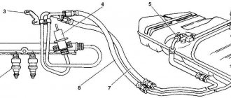
Fuel supply diagram for an engine with a fuel injection system
1 – injectors 2 – fitting plug for monitoring fuel pressure 3 – injector ramp 4 – bracket for fastening fuel pipes 5 – fuel pressure regulator 6 – canister with solenoid valve 7 – hose for sucking gasoline vapors from the canister 8 – throttle assembly 9 – two-way valve 10 – gravity valve 11 – safety valve 12 – separator 13 – separator hose 14 – fuel tank plug 15 – filler pipe 16 – filler pipe hose 17 – fuel filter 18 – fuel tank 19 – electric fuel pump 20 – fuel drain line 21 – fuel supply line
Fuel is supplied from a tank installed under the bottom in the rear seat area. The fuel tank of the VAZ 2111 is made of steel and consists of two stamped halves welded together. The filler neck is connected to the tank with a gas-resistant rubber hose secured with clamps. The plug is sealed. The fuel pump is electric, submersible, rotary, two-stage, installed in the fuel tank. The developed pressure is at least 3 bar (3 atm).
The VAZ 2110 fuel pump is turned on at the command of the injection system controller (with the VAZ 2112 ignition on) via a relay. To access the pump, there is a hatch under the rear seat in the bottom of the car. From the pump, fuel under pressure is supplied through a flexible hose to the fine filter and then through steel fuel lines and rubber hoses to the fuel rail.
The fine fuel filter is non-separable, in a steel housing, with a paper filter element. There is an arrow on the filter housing that must coincide with the direction of fuel movement.
The fuel rail serves to supply fuel to the injectors and is mounted on the intake manifold. On one side there is a fitting for monitoring the fuel pressure, on the other there is a pressure regulator. The latter changes the pressure in the fuel rail - from 2.8 to 3.2 bar (2.8-3.2 atm) - depending on the vacuum in the receiver, maintaining a constant difference between them. This is necessary for accurate dosing of fuel by injectors.
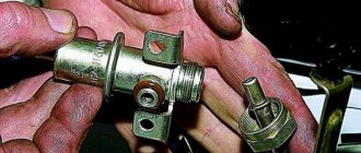
The fuel pressure regulator VAZ 2111, VAZ 2112 is a fuel valve connected to a spring-loaded diaphragm. The valve is closed under the action of the spring. The diaphragm divides the regulator cavity into two isolated chambers - “fuel” and “air”. The “air” is connected by a vacuum hose to the receiver, and the “fuel” is connected directly to the ramp cavity. When the engine is running, the vacuum, overcoming the resistance of the spring, tends to retract the diaphragm, opening the valve. On the other hand, fuel presses on the diaphragm, also compressing the spring. As a result, the valve opens and part of the fuel is released through the drain pipe back into the tank. When you press the gas pedal, the vacuum behind the throttle valve decreases, the diaphragm, under the action of a spring, closes the valve - the fuel pressure increases. If the throttle valve is closed, the vacuum behind it is maximum, the diaphragm pulls the valve harder - the fuel pressure decreases. The pressure difference is set by the spring stiffness and the size of the valve opening and cannot be adjusted. The pressure regulator is non-separable; if it fails, it is replaced.
The injectors are attached to the ramp through rubber sealing rings. The injector is an electromagnetic valve that allows fuel to pass through when voltage is applied to it, and closes under the action of a return spring when there is no power. At the injector outlet there is a nozzle through which fuel is injected into the intake manifold. The injection system controller controls the injectors. If there is a break or short circuit in the injector winding, it should be replaced. If the injectors become clogged, they can be washed without dismantling at a special service station.
The feedback injection system uses the VAZ 2110 fuel vapor recovery system. It consists of an adsorber installed in the engine compartment, a separator, valves and connecting hoses. Fuel vapor from the tank partially condenses in the separator, and the condensate is drained back into the tank. The remaining vapor passes through gravity and two-way valves. The gravity valve prevents fuel from leaking out of the tank when the VAZ 2111 car rolls over, and the two-way valve prevents excessive increase or decrease in pressure in the fuel tank.
Then the fuel vapors enter the VAZ 2110 adsorber, where they are absorbed by activated carbon. The second fitting of the adsorber is connected by a hose to the throttle assembly, and the third to the atmosphere. However, when the engine is turned off, the third fitting is closed by an electromagnetic valve, so that in this case the adsorber does not communicate with the atmosphere. When the engine starts, the injection system controller begins to send control pulses to the valve with a frequency of 16 Hz. The valve communicates the adsorber cavity with the atmosphere and the sorbent is purged: gasoline vapors are sucked through the hose into the receiver. The greater the engine's air consumption, the longer the duration of the control pulses and the more intense the purging.
In an open-loop injection system, the fuel vapor recovery system consists of a separator with a two-way check valve. The VAZ 2111 air filter is installed in the front left part of the engine compartment on three rubber holders (supports). The filter element is made of paper; when installing, its corrugations should be located parallel to the axis of the car. After the filter, the air passes through the mass air flow sensor and enters the intake hose leading to the throttle body. The throttle assembly is fixed to the receiver. By pressing the gas pedal, the driver slightly opens the throttle valve, changing the amount of air entering the engine, and therefore the combustible mixture - after all, the fuel supply is calculated by the controller depending on the air flow. When the engine is idling and the throttle valve is closed, air flows through the idle air control valve, a valve controlled by the controller. The latter, by changing the amount of supplied air, maintains the idle speed specified (in the computer program). The idle speed regulator of the VAZ 2112 is non-separable; if it fails, it is replaced.
Features of the power supply system for engines 21124 and 21114
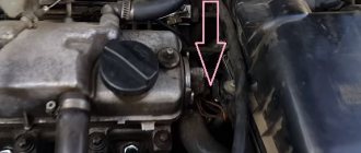
Location of engine power system elements
[Engine with decorative trim removed.]
21124 (1.6i 16V) in the engine compartment:
1
-
inlet pipe;
2 —
throttle assembly;
3 — air supply hose to the throttle valve; 4 — air intake; 5 — air filter; 6 — fuel rail; 7 — throttle valve drive cable; 8 — diagnostic fitting; 9 — adsorber check valve; 10 -
adsorber
Location of engine power system elements
[Engine with decorative trim removed.]
21114 (1.6i 8V) in the engine compartment:
1
-
adsorber check valve;
2 — diagnostic fitting; 3 - receiver; 4 - throttle assembly; 5 - fuel rail; 6 — air supply hose to the throttle valve; 7 — corrugated air intake hose; 8 — air filter; 9 — throttle valve drive cable; 10 -
adsorber
On the 21124 engine, the receiver is combined with the intake manifold into a single unit and is made of plastic. On engine 21114, only the receiver is made of plastic.
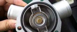
There are two valves in the filler neck of the fuel tank: one for emergency release of fuel vapor pressure from the tank (which is possible when the ambient temperature rises), and the other for the entry of air from the atmosphere when fuel is consumed from the tank (this eliminates the occurrence of strong vacuum in the tank ).
Engine inlet pipe 21124 (1.6i 16V): 1
— a flange with an o-ring for fastening the throttle pipe; 2 - receiver; 3 - intake manifold flange with o-rings for connection to the cylinder head
Engine receiver 21114 (1.6i 8V):
1 — flange with an o-ring for fastening the throttle pipe; 2 - receiver with o-rings for connection to the inlet pipeline
Fuel module for engines 21124 and 21114 (1.6i):
1 — inlet pipe (for supplying fuel to the pressure regulator); 2 - outlet (discharge) pipe; 3 — module cover; 4 — fuel level indicator sensor; 5 - intake chamber; 6 — module cover guide
The fuel pump is combined with a fuel level sensor and a fuel pressure regulator into a single unit - a fuel module (often called an electric fuel pump). Fuel from the pump (through the outlet pipe of the fuel module) enters the fuel filter. Purified gasoline is again supplied through the fuel line and through a tee to the inlet pipe of the fuel module and then fed into the fuel rail. Excess fuel flows through the pressure regulator back into the tank. The fuel pressure regulator is installed in the fuel module cover.
>
Diagram of the power supply system for engines 21124 and 21114 (1.6i):
1 — nozzles; 2 - fuel rail; 3 — diagnostic fitting; 4 - adsorber; 5 - check valve; 6 — throttle assembly; 7 - gravity valve; 8 - separator; 9 — fuel line tube connecting the fuel filter to the tee; 10 — fuel line tube connecting the fuel filter to the outlet pipe of the fuel module; 11 — fuel module; 12 — fuel filter; 13 - filler pipe; 14 — fuel tank; 15 — hose connecting the fuel filter and the fuel module with the fuel line; 16, 18 — metal fuel pipes; 17 — connecting hose; 19 — fitting for connecting the fuel rail to the fuel line.
Note. On the 21114 engine, the shape of the fuel rail has minor differences (see below).
Fuel pressure regulator for engines 21124 and 21114 (1.6i):
1 — hole for dumping excess fuel; 2, 4 — sealing rings; 3 — holes for supplying fuel to the regulator; 5 — body; 6 - terminal for connecting the regulator to ground
Fuel rail for engines 21114 (1.6i 8V) (a) and 21124 (1.6i 16V) (b) assembled with injectors:
1 — diagnostic fitting; 2 - fuel rail; 3 — fitting for connecting to the fuel line; 4, 5, 6 and 7 - injectors
Source
Fuel supply diagram for an engine with a fuel injection system
1 – nozzles; 2 – fitting plug for monitoring fuel pressure; 3 – injector ramp; 4 – bracket for fastening fuel pipes; 5 – fuel pressure regulator; 6 – adsorber with solenoid valve; 7 – hose for suction of gasoline vapors from the adsorber; 8 – throttle assembly; 9 – two-way valve; 10 – gravity valve; 11 – safety valve; 12 – separator; 13 – separator hose; 14 – fuel tank plug; 15 – filling pipe; 16 – filling pipe hose; 17 – fuel filter; 18 – fuel tank; 19 – electric fuel pump; 20 – fuel drain line; 21 – fuel supply line.
Fuel is supplied from a tank installed under the bottom in the rear seat area. The fuel tank is made of steel and consists of two stamped halves welded together. The filler neck is connected to the tank with a gas-resistant rubber hose secured with clamps. The plug is sealed.
The fuel pump is electric, submersible, rotary, installed in the fuel tank. The developed pressure is at least 3 bar (300 kPa).
The fuel pump is turned on at the command of the injection system controller (with the ignition on) through a relay. To access the electrical connector of the pump, there is a hatch under the rear seat in the bottom of the car. From the pump, fuel under pressure is supplied through a flexible hose to the fine filter and then through steel fuel lines and rubber hoses to the fuel rail.
The fine fuel filter is non-separable, in a steel housing, with a paper filter element. There is an arrow on the filter housing that must coincide with the direction of fuel movement.
The fuel rail serves to supply fuel to the injectors and is mounted on the intake manifold. On one side there is a fitting for monitoring the fuel pressure, on the other there is a pressure regulator. The latter changes the pressure in the fuel rail - from 2.8 to 3.2 bar (280-320 kPa) - depending on the vacuum in the receiver, maintaining a constant difference between them. This is necessary for accurate dosing of fuel by injectors.
The fuel pressure regulator is a fuel valve connected to a spring-loaded diaphragm. The valve is closed under the action of the spring. The diaphragm divides the regulator cavity into two isolated chambers - “fuel” and “air”. The “air” is connected by a vacuum hose to the receiver, and the “fuel” is connected directly to the ramp cavity. When the engine is running, the vacuum, overcoming the resistance of the spring, tends to retract the diaphragm, opening the valve. On the other hand, fuel presses on the diaphragm, also compressing the spring. As a result, the valve opens and part of the fuel is released through the drain pipe back into the tank. When you press the gas pedal, the vacuum behind the throttle valve decreases, the diaphragm, under the action of a spring, closes the valve - the fuel pressure increases. If the throttle valve is closed, the vacuum behind it is maximum, the diaphragm pulls the valve harder - the fuel pressure decreases. The pressure drop is determined by the spring stiffness and the size of the valve opening; cannot be adjusted. The pressure regulator is non-separable; if it fails, it is replaced.
The injectors are attached to the ramp through rubber sealing rings. The injector is an electromagnetic valve that allows fuel to pass through when voltage is applied to it and closes under the action of a return spring when there is no power. At the injector outlet there is a nozzle through which fuel is injected into the intake manifold. The injection system controller controls the injectors. If there is a break or short circuit in the injector winding, it should be replaced. If the injectors become clogged, they can be washed without dismantling at a special service station.
The closed-loop injection system uses a fuel vapor recovery system. It consists of an adsorber installed in the engine compartment, a separator, valves and connecting hoses. Fuel vapor from the tank partially condenses in the separator, and the condensate is drained back into the tank. The remaining vapor passes through gravity and two-way valves. The gravity valve prevents fuel from leaking out of the tank when the vehicle rolls over, and the two-way valve prevents excessive increase or decrease in pressure in the fuel tank.
Then the fuel vapor enters the adsorber, where it is absorbed by activated carbon. The second fitting of the adsorber is connected by a hose to the throttle assembly, and the third is connected to the atmosphere. However, when the engine is turned off, the third fitting is closed by an electromagnetic valve, so that in this case the adsorber does not communicate with the atmosphere. When the engine starts, the injection system controller begins to send control pulses to the valve with a frequency of 16 Hz. The valve communicates the adsorber cavity with the atmosphere and the sorbent is purged: gasoline vapors are sucked through the hose into the receiver. The greater the engine's air consumption, the longer the duration of the control pulses and the more intense the purging.
In an open-loop injection system, the fuel vapor recovery system consists of a separator with a two-way check valve. The tube connecting the tank to the atmosphere is led into the cavity of the rear right wing.
The air filter is installed in the front left part of the engine compartment on three rubber holders (supports). The filter element is paper.
After the filter, the air passes through the mass air flow sensor and enters the intake hose leading to the throttle body.
The throttle assembly is fixed to the receiver. By pressing the gas pedal, the driver slightly opens the throttle valve, changing the amount of air entering the engine, and therefore the combustible mixture, because the fuel supply is calculated by the controller depending on the air flow. When the engine is idling and the throttle valve is closed, air flows through the idle air control valve, a valve controlled by the controller. By changing the amount of supplied air, the controller maintains the idle speed specified (in the computer program). The idle speed regulator is non-separable; if it fails, it is replaced.
VAZ 2110 engine 8 valves, design of the “tens” injection engine, power circuit
The VAZ 2110 8-valve engine became the first power unit to appear on the “top ten”. At first it was a carburetor engine, which differs little from the 08 engine, which we will talk about today, and then they mastered the production of the VAZ 2110 with an 8-valve injection engine. The device of which we will also consider.
In total, during the production of the “ten”, three 8-valve engines were under the hood of this car. This is a carburetor with a volume of 1.5 liters, an injector of the same volume and an 8-valve injector, but with a volume of 1.6 liters. These are engine models 2110, 2111 and 21114 respectively. The main difference between the 1.5 and 1.6 liter engines is the increased piston stroke from 71 to 75.6 mm, due to which the volume increased. At the same time, the cylinder diameter remained the same 82 mm. The height of the cylinder block and the crankshaft configuration have increased.
To begin with, we will take a detailed look at the structure of the VAZ-2110 engine with a carburetor power system, so that we can then clearly understand the differences between the injection version of the VAZ 2110 8-valve engine and the carburetor version. So, pay attention to the picture, just below.
The “tens” unit differed from the 08 engine only in the presence of an original camshaft. Otherwise, the layout is almost the same as on the G8, the same components and parts. For convenience, everything in this picture is numbered.
Engine structure VAZ 2110 8 valves, carburetor
1 – generator drive pulley (damper); 2 – oil pump; 3 – toothed pulley of the coolant pump; 4 – connecting rod; 5 – piston pin; 6 – tension roller; 7 – camshaft toothed pulley; 8 – front cover of the timing mechanism drive; 9 – timing belt; 10 – rear cover of the camshaft drive; 11 – camshaft oil seal; 12 – cylinder head cover; 13 – camshaft; 14 – front cover of camshaft bearings; 15 – oil separator mesh for the crankcase ventilation system; 16 – rear cover of camshaft bearings; 17 – oil filler cap; 18 – fuel pump; 19 – ignition distributor; 20 – housing of auxiliary units; 21 – outlet pipe of the cooling jacket; 22 – pusher; 23 – valve spring; 24 – coolant temperature sensor; 25 – valve; 26 – cylinder head; 27 – cylinder block; 28 – piston; 29 – flywheel; 30 – crankshaft rear oil seal holder; 31 – rear crankshaft oil seal; 32 – crankshaft; 33 – main bearing cover; 34 – oil pan; 35 – oil pump receiver; 36 – connecting rod cover; 37 – front crankshaft oil seal; 38 – crankshaft toothed pulley; 39 – oil pan drain plug; 40 – oil filter; 41 – coolant pump; 42 – exhaust manifold; 43 – intake manifold; 44 – carburetor; 45 – valve adjusting washer; 46 – crankcase ventilation hose; 47 – valve holder; 48 – valve guide; 49 – oil dipstick.
The main difference between the VAZ 2110 injection engine is 8 valves in the power system, which is much more complicated, but this has its advantages. The injection engine is more economical, more powerful, works better and more stable. However, such an engine requires diagnostic equipment for maintenance, without which it can be extremely difficult to identify poor operation of the power unit.
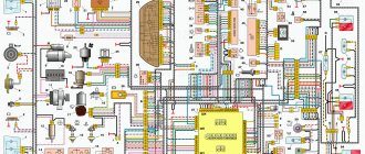
Electrical diagram of VAZ-2112
Designations: 1 – Headlight, 2 – Klaxon, 3 – Main radiator fan, 4 – Starter, 5 – Battery, 6 – Generator 2112, 7 – Gearbox limit switch (reverse), 8 – Actuator in the front passenger door, 9 – Power window enable relay, 10 – Starter relay, 11 – Heater fan, 12 – Electric heater partition drive, 13 – Main pump, 14 – Washer reservoir sensor, 15 – Driver’s door actuator, 16 – Front passenger window selector, 17 – Unlock button fifth door, 18 – Heater fan resistance unit, 19 – Main wiper motor, 20 – Driver’s window lift selector, 21 – Front passenger’s window lift motor, 22 – Central locking, 23 – Exterior light switch, 24 – Brake fluid leakage sensor, 25 – Pump additional, 26 – Driver's window lift motor, 27 – PTF on indicator, 28 – PTF switch, 29 – Dashboard, 30 – Heated glass on indicator, 31 – Heated glass switch, 32 – Steering column selector switch, 33 – PTF relay, 34 – Ignition switch, 35 – Main fuse block, 36 – Illumination of heater controls, 37 – Hazard warning button, 38 – Heater control controller, 39 – Glove compartment lighting, 40 – Glove compartment lid end cap, 41 – Cigarette lighter, 42 – BSK – display unit, 43 – Ashtray illumination, 44 – 12V socket, 45 – Instrument lighting switch, 46 – Actuator in the right rear door, 47 – Right rear passenger window selector, 48 – Clock, 49 – Right rear passenger window motor, 50 – Brake limit switch (closed – pedal is pressed), 51 – Left rear passenger window motor, 52 – Left rear passenger window selector, 53 – Actuator in the left rear door, 54 – Turn signal, 55 – Handbrake limit switch (closed – handbrake on), 56 – Rear wiper motor , 57 – Navigator's lamp, 58 – Interior lamp, 59 – Temperature sensor in the heater, 60 – Limit switch for the open front door, 61 – Limit switch for the open rear door, 62 – Trunk light, 63 – Rear optics (on the body), 64 – Rear optics (on the fifth door), 65 – License plate illumination.
The letters indicate the terminals to which it is connected: A – Front speaker on the right, B – Radio, C – Injector harness, D – ESD diagnostic connector, D – Front left speaker, E – Diagnostic connector for the heater controller, G – Rear right speaker, W – Rear left speaker, I – BC connector, K – glass heater thread, L – fifth door actuator, M – Additional brake light.
Wiring diagram VAZ-2112 injector 16 valves - full view
VAZ 2110 engine power supply diagram 8 valves injector
The power supply system of an injection engine with 8 valves (these are engines 2111 1.5 liters and 21114 1.6 liters) consists of the following elements. Let's look at the image below.
Sealed tank with built-in electric fuel pump, which constantly provides the required pressure in the rail. The ramp contains injectors that inject fuel into the engine. In this case, the process is controlled by electronics, which sends a pulse to the injector solenoid valve, it opens and fuel is injected into the combustion chamber, and due to a mechanical return spring, the injector closes, cutting off the fuel supply. The pressure created in the injector fuel system is about 3 atmospheres. Actually, without this, not a single injection engine will work, especially if the fuel system is not sealed.
It is worth noting that the VAZ 2110 injection engine has 8 valves , among other things, there are a number of sensors, without which stable operation of the engine is not possible, these are an oxygen concentration sensor, a mass air flow sensor, a throttle position sensor. Data from the sensors is constantly transmitted to the engine control unit, which is a computing module programmed for a specific engine operating mode. It is this block that determines when and how much fuel needs to be injected into the internal combustion chambers of the engine. Some craftsmen even reprogram this unit, making the VAZ-2110 engine more powerful, but such a unit at the same time becomes more voracious.
Design of the VAZ 2110 fuel pump for injection and carburetor car models
Two types of fuel pumps are installed on VAZ 2110 cars, depending on the type of car engine. The first type, mechanical, is installed mainly on carburetor models, the second type is electrical, which are installed on inverter tens.
Mechanical fuel pumps, which were installed on the first modifications of the VAZ 2110/2112, have a simple design. It is based on a set of membranes made of special rubberized fabric that is resistant to the chemical action of gasoline. The pump body has two valves: inlet and outlet. The membranes are driven by a rod (pusher). It is driven by a cam mechanism rotated by a camshaft.
Such a mechanical fuel pump can serve for decades until the drive rod wears out or one of the membranes breaks. And even then, if this happens, you can replace these elements in half an hour.
With an electric fuel pump, things are much more complicated. Its design is based on a small electric motor. It is no different from a regular one, although it works completely immersed in gasoline. The pressure in the system here is created not by a membrane (although there are such pumps), but by a specially shaped impeller mounted on the electric motor shaft.
The VAZ 2110 fuel pump is located directly in the car’s tank.
The service life of the electric fuel pump is 150–200 thousand km. But it can fail much earlier. The main cause of breakdowns when the resource is not used up is additives added to gasoline, as well as various kinds of mechanical impurities. The former destroy the brushes and commutator, while the latter clog the valve mechanisms.
Repair manual for VAZ 2110, 2112, 2111 (Lada 110)
The power supply system includes elements of the following systems:
– a fuel supply system, including a fuel tank, a fuel pump, a pressure regulator, a fuel filter, a ramp with injectors, hoses and pipelines;
– an air supply system, which includes an air filter, an air supply pipe, a throttle assembly;
– a fuel vapor recovery system consisting of an adsorber and connecting pipelines.
The functional purpose of the fuel supply system is to ensure the supply of the required amount of fuel in all operating modes.
4.17. Engine fuel supply system mod. 2111 and 2112: 1 – fitting plug for monitoring fuel pressure; 2 – injector ramp; 3 – bracket for fastening fuel pipes; 4 – fuel pressure regulator; 5 – fuel pump; 6 – fuel filter; 7 – fuel drain line; 8 – fuel supply line; 9 – nozzles
Design of the motor power supply system mod. 2111 and 2112 (Fig. 4.17) differs from the power supply system for mod. 21114 and 21124 (Fig. 4.18) in that the latter do not have a return fuel line, since the pressure regulator is installed directly in the gas tank in the fuel pump module. In addition, for connecting elements of the fuel line on engines mod. 21114 and 21124 use special clamping tips instead of threaded fittings, the shape and design of the fuel rail are changed, new injectors are used, and the pressure is increased.
4.18. Engine fuel supply system mod. 21114 and 21124: 1 – fitting plug for monitoring fuel pressure; 2 – injector ramp; 3 – fuel pump module; 4 – fuel filter; 5 – tee; 6 – fuel supply line; 7 – nozzles
Features of the power supply system for engines 2112 and 2111
Elements of the power supply system for engines 2112 and 2111 (1.5i):
1 — nozzles; 2 - fuel rail; 3 — diagnostic fitting; 4 - adsorber; 5 - check valve; 6 — throttle assembly; 7 - gravity valve; 8 - safety valve; 9 - separator; 10 — fuel tank filler pipe; 11 — fuel filter; 12 — fuel supply line; 13 — fuel line hose connecting the outlet (discharge) pipe of the fuel module with the fuel filter; 14 — fuel module; 15 — fuel tank; 16 — fuel drain line; 17 - fuel pressure regulator.
Note. The fuel supply line on the 2111 engine is connected to the fuel rail at the end (see below).
Location of engine power system elements
[Engine with decorative trim removed.]
2112 (1.5i 16V) in the engine compartment:
1
-
receiver; 2 — throttle assembly; 3 — air supply hose to the throttle valve; 4 — air filter; 5 — fuel pressure regulator; 6 — throttle valve drive cable; 7 — fuel rail; 8 — diagnostic fitting; 9 — adsorber check valve; 10 - adsorber
Location of elements of the engine power supply system 2111 (1.5i 8V) in the engine compartment:
1
—
canister check valve; 2 — diagnostic fitting; 3 - receiver; 4 - throttle assembly; 5 — fuel pressure regulator; 6 — air supply hose to the throttle valve; 7 — air intake; 8 — air filter; 9 — fuel rail; 10 — throttle valve drive cable; 11 - adsorber
Air is supplied to the inlet valves of the cylinders of engines 2112 and 2111 through a receiver and an inlet pipeline made of aluminum alloy.
Fuel pump
combined with the fuel level indicator sensor into a single unit -
a fuel module
(often called an electric fuel pump). The pressure pump delivers fuel from the tank through the fuel filter to the fuel rail.
Fuel pressure control
installed on the fuel rail. Excess fuel is returned to the tank through the fuel return line.
Fuel rail for engine 2112 (1.5i 16V) assembly
with
injectors:
1
—
fuel supply tube to the fuel rail; 2 — fuel pipe for draining fuel into the tank; 3, 4, 5 and 6 - nozzles; 7 — diagnostic fitting (to check the fuel pressure, closed with a threaded cap); 8 — fuel rail; 9 - fuel pressure regulator
Fuel rail for engine 2111 (1.5i 8V) assembly
with
nozzles:
1 — diagnostic fitting; 2 - fuel rail; 3 — fuel supply tube to the fuel rail; 4 — fuel pressure regulator; 5 — tube for draining (draining) fuel into the tank; 6, 7, 8 and 9 injectors
Diagram of the fuel system of the 16-valve injection VAZ-2112
The fuel system is one of the most important components in any car. After all, without it it is simply impossible to imagine the full operation of the vehicle. And so that you can imagine what the fuel system on your VAZ-2112 consists of, below we will present you with its detailed diagram, with a detailed description of each of the main elements.
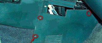
How to replace the fuel pump on a VAZ 2110 with your own hands - step-by-step instructions
In order to replace the fuel pump on a VAZ 2110, you must perform the following procedure:
- Disconnect the negative battery terminal;
- Relieve the residual pressure in the fuel rail using a special fitting;
The “tens” fuel pump is located under the rear seat of the car. We recline the seat and unscrew the protective cover;
Disconnect the electrical terminal block of the pump, unscrew the fuel supply and drain lines.
The rubber gaskets for the tips of the lines should be replaced;
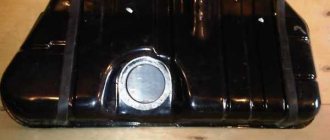
On a VAZ 2112, the fuel pump is held in place by eight bolts on an O-ring with a lining
All you have to do is remove the old fuel pump and install a new one according to the indicating arrow on the body of the product.
Detailed diagram of the fuel system
Detailed diagram of the fuel system.
1 — nozzles; 2 — fitting plug for monitoring fuel pressure; 3 — injector ramp; 4 — bracket for fastening fuel pipes; 5 — fuel pressure regulator; 6 — adsorber with solenoid valve; 7 — hose for suction of gasoline vapors from the adsorber; 8 — throttle assembly; 9 - two-way valve; 10 - gravity valve; 11 - safety valve; 12 - separator; 13 — separator hose; 14 — fuel tank plug; 15 - filling pipe; 16 — filling pipe hose; 17 — fuel filter; 18 — fuel tank; 19 — electric fuel pump; 20 — fuel drain line; 21 - fuel supply line.
Below we will look at the main elements of the fuel system separately.
Fuel tank
Dismantled VAZ-2112 gas tank.
The filled gasoline is supplied from the tank, which is located in the rear of the car, in the area where the sofa is located . The tank is made of steel and assembled by welding two stamped parts. Gasoline is supplied to the tank through a special neck, from a gas-resistant hose made of rubber, secured together with clamps.
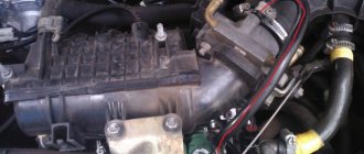
Gasoline pump
Fuel pump VAZ-2112 1139009
A gas pump is an electrical functional device, submersible, installed directly into the gas tank itself. This pump is started by a signal from the ECU controller, which is responsible for fuel injection, through a relay when the ignition is turned on. If the fuel pump doesn't pump, the engine won't start! The operating pressure of the pump is at least 2.8-3 bar (atmospheres - approx.). In order to get to it, just lift the rear sofa and unscrew the technical hatch.
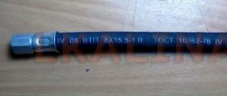
Fine filter
The new filter is ready for installation.
From the fuel pump, through a flexible steel hose, gasoline passes under pressure to the fine filter. The filter is made of steel and cannot be disassembled. A special paper filter element is installed inside. On the housing cover there is a special arrow, created for visual indication during installation, showing the direction of movement of gasoline in the system.
Fuel rail
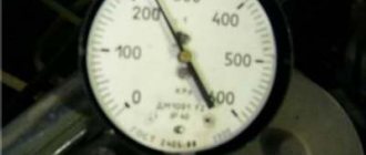
Through steel fuel pipes, after filtration, gasoline passes directly to the fuel rail. It is designed to transfer gasoline to atomization and is mounted on the “outlet”. On one side of the fuel rail there is an RTD, on the other there is a fitting for controlling gasoline pressure. The pressure in the ramp in operating condition should be from 2.8 to 3.2 bar ( 2.8-3.2 atmospheres - approx.) - this indicator depends on the stabilization in the receiver, indicating constant differences in them. This is necessary in order to dose the optimal amount of gasoline into the injectors.
Fuel pressure control
Be careful when dismantling.
An RTD is a special device with a valve, assembled with a special diaphragm with a spring retainer. Under the influence of this element, the working position is in the locked type. It is also designed to divide the internal space of the regulator itself into two closed cavities - air and fuel.
The cavity for air is connected to the hose and receiver, and for fuel it is connected to the structure itself on the ramp.
During operation of the motor, the vacuum overcomes the resistance created by the spring and tries to tighten the diaphragm, thereby opening the valve. And from another position, at this time, gasoline presses on the diaphragm, also influencing the spring. As a result of this action, the valve opens slightly and part of the fuel flows back into the gas tank through the fuel line.
When the gas is pressed, the vacuum behind the throttle valve (throttle valve - approx.) becomes less, and the diaphragm, under the influence of a spring, closes the valve, increasing the fuel pressure. And if it is closed, the vacuum pulls the valve as far as possible - reducing fuel pressure.
The total pressure drop in the sensor is determined by the stiffness of the spring and the size of the hole. It cannot be adjusted, it is a non-separable element, and when it fails it must be replaced.
Fuel rail with injectors
An injector is a special solenoid valve that is needed to transfer gasoline to the manifold when current is applied to it, and close under the influence of a return spring when the power is turned off. They are mounted in place of fixation through special rubber rings and held there with a metal bracket. It is controlled by the ECU from the injection system. If a break or short circuit occurs in the injection wiring, the injectors should be replaced.
Injection system
An injection system in which feedback is provided and a fuel evaporation trap is installed. It consists of an adsorber, a separator, connection hoses and valves mounted under the hood. Its action is as follows:
- Some of the fuel vapor that accumulates in the tank is condensed in the separator and then drained back into the tank. And the rest pass through two-way and gravity valves.
- A two-way valve prevents excessive decrease and increase in pressure inside the fuel tank, and a gravity valve prevents fuel from leaking out when the vehicle rolls over.
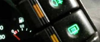
Vapor recovery system
This is what the adsorber looks like on a VAZ-2112.
Afterwards, fuel vapors go through one fitting into the engine compartment - namely into the adsorber, where coal is installed to absorb them. The second fitting of the adsorber is connected to the throttle units using a tube, and the third is directly connected to the atmosphere. However, when the engine is not running, the 3rd fitting is closed by a valve and in this state the remaining elements are not associated with air. And when starting the engine, the controller of the system responsible for injection sends a signal to the valves with a frequency of 15-16 Hz , communicating the adsorber itself with the atmosphere. During such work, if the air flow rate is higher and the intensity of the pulses passes through more, then the blowing will be much more efficient.
And where this feedback does not exist, fuel vapors are “caught” only by a separator and one check valve.
Injection system design
F2 - 7.5A - Left headlight low beam.
Subsequently, the controller, based on the information coming from the on-board computer, makes a decision on the position and duration of opening of the injector damper. In principle, a novice motorist can understand its operation. In this case, the problem definitely does not lie in the control unit, the problem is related to malfunctions in the controller. The role of the electronic control unit in the overall injector circuit. From a practical point of view, the electronic control unit consists of several high-tech components: ROM - memory devices, PROM - dynamic memory devices, RAM - regulatory memory; all of the above elements function only if there is voltage available . Relay for monitoring the health of brake light lamps and side lights. There are slight differences, but the basic principles of operation and wiring are the same. But this does not take away the fact that many have dozens of them under the hood with a carburetor. The crankshaft, rotating, fills the cylinder with fuel, the size of its volume is determined by the state of the injector, and the operation of the injector is carried out by the controller. Thanks to this program, the moment and volume of gasoline supply to the chambers where internal combustion occurs is set.
The positive terminal that comes from the battery to consumers is always red. Unstable operation at low speeds. Generator excitation winding. For each system that is connected to the electrical system, it is equipped with its own separate wiring harness. Advice: make sure that the pressure in the fuel supply system does not exceed MPa.
Indicator lamp for turning on the high beam. How to look for faults? A pump is built in to supply gasoline and maintain the required pressure in the rail. The collapsible design allows for vehicle maintenance and repair. Checking the wires using a multimeter with the battery disconnected.
To check their condition, you need to carefully inspect all the wires that are laid in the harness. However, without protection on the VAZ there is: A wire from the battery charge relay to the battery itself, VAZ wiring to the injector, which is responsible for the ignition and engine starting circuits; Generator wiring excluding the field winding, which is activated after turning the key in the ignition and starting the engine. It allows you to move the damper, changing the angle of its opening, as well as the amount of cold air entering the heater from outside. VAZ 2110 21124 engine troubles, stalls, twitches (problem solution)