But there are also versions of the car in which the wiring is directly connected to the contacts, and when installing a new element with this type of wiring connection on a VAZ-2101, an ignition switch circuit will be required.
If the lock assembly is replaced, then you can connect the wiring to the new one, install it in place, secure it and cover it with a decorative panel.
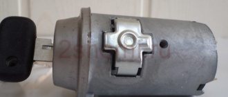
If only the contact group is changed, then the removed lock is disassembled. The contact group is fixed using a locking ring, which must be pryed off with an awl or screwdriver and removed. After this you can remove the group. A new one is installed in its place and secured with the same retaining ring. After this, everything is put in place and the VAZ-2101 ignition switch is connected.
Connection
Now about the connection. If the wires are assembled into a chip, then there will be no difficulties - we install the chip correctly on the contacts and that’s it.
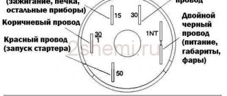
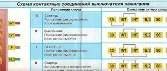
If each wire is connected separately, then you need to follow the diagram:
- To pin 50 – red wire (responsible for the operation of the starter);
- To pin 15 – blue with a black stripe (ignition, interior heating and other devices);
- Pin 30 – pink wire;
- Pin 30/1 – brown wire;
- INT – black wire (dimensions and headlights);
After connecting the wiring, everything is assembled, the terminal is connected to the battery and the functionality is checked. First you need to check whether all electrical appliances powered by the lock are working. Then check the functionality of the starter.
If something does not work, you need to remove the lock and once again check that the wiring is connected correctly, since this alone determines the operation of the devices when you turn the key.
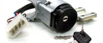
The structure of a car ignition switch
- Locking rod
- Frame
- Roller
- Contact disc
- Contact sleeve
- Block
- Protrusion of the contact part.
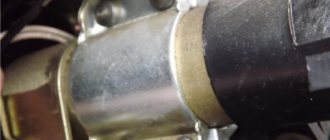
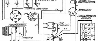
The lock mechanism is connected to many wires. They continue from the battery, connecting all the electrical devices of the car into a single chain. When you turn the ignition key, the electrical circuit is closed from the “-” terminal of the battery to the ignition coil. As a result, the current passes through the wires to the ignition switch, through its contacts it is directed to the induction coil, after which it returns back to the “+” terminal. As electricity passes through the coil, it generates high voltage, which it transmits to the spark plug. Therefore, the key closes the contacts of the ignition circuit, thereby starting the car engine.
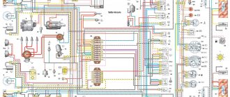
Electrical diagram of VAZ 2104
The electrical equipment of the machine is protected by fuse links installed in the mounting block. The battery charging circuit, ignition and engine start circuits, and the high and low beam relay windings are not protected by fuses. Before replacing a blown fuse link, correct the problem that caused the fuse to blow. When looking for a problem, I advise you to look at the circuits that protect this fuse.
In cars produced before 1988, the fog lights in the rear lights and the fog light warning lamp were protected by fusible insert No. 17 of the mounting block. Since 1988, they have been protected by a separate fuse in the wiring harness near the fog light switch. This insert is designed for current flow up to 8A.
Until 1988, the glove compartment light was protected not by fuse No. 15, but by a second fuse. All fuses and various auxiliary relays were mounted in a separate block in the engine compartment. Also, through the mounting block, the wiring harnesses of the engine compartment are connected to the dashboard harness and to the rear harness.
The mounting blocks are quite easy to disassemble and repair. The old-style block (with finger inserts) consists of two parallel-connected printed circuit boards; the new-style blocks (with knife inserts) have one board. Soldering of wires is allowed in case of bypassing burnt-out tracks on printed circuit boards, but only if this does not require disconnecting the PCB.
The principle of operation of the immobilizer and its design
The immobilizer works as follows: before starting the car’s ignition system, the owner must either enter an identification “PIN code”, consisting of a series of presses on the function keys of the dashboard, or activate the immobilizer using a microchip that is sewn into the key, car key fob and even plastic card.
Otherwise, the car may be blocked when you try to start it. Some models of immobilizers allow you to start a car and even drive it for a short distance. After the car stalls, the attacker has no choice but to leave the vehicle. The owner of the car has the opportunity to immediately find the car. The immobilizer consists of three parts:
- Control block.
- Electromagnetic relay.
- Key.
Each of these elements has its own purpose. So, the control unit activates the device after sending the appropriate signal. Relays immobilize the vehicle by interrupting electrical networks. Well, the key is a control element that can deactivate the security system and start the vehicle.
However, an immobilizer does not provide 100% protection for a car. An attacker can use the device's diagnostic connector to deactivate it. The connector is located in an easily accessible place, through which a car thief can register another key and put the control unit into emergency mode (when this mode is activated, the immobilizer does not respond to attempts to start the car).
Additionally, by using the CAN bus, an attacker can use capital keys for emulation. There are often cases when a winder is inserted into the connector; literally in half a minute it breaks the standard security system and adds a key that can be used by an attacker during theft.
A car thief can also replace the ECU and immobilizer unit, rendering this device useless in the fight against theft. Also, attackers can relay the immobilizer key code, or simply steal the latter.
Electrical diagram of VAZ-2104 with symbols
Reference information for the vehicle in DJVU format. For high-quality display, I recommend using the DJVU viewer
VAZ 21041-30 with ECU M 74k (Factory diagram) (for injection cars assembled in Izhevsk)
Electrical connection diagram of the VAZ-2104 engine control system with the “January-5.1.3” controller
The VAZ-21045 design is distinguished by the exclusion of some ignition system components and the addition of engine starting system components and cooling system fans. Conductor color designations: BC – white with black; B – white; GP – blue with magenta; G – blue; GC – blue with black; ZCh – green with black; G – green; K – brown; P – purple; O – orange; P – pink; SP – gray with purple; C – gray; H – black.
Glow plug control system
1 – ignition switch; 2 – mounting block; 3 – engine preheating indicator; 4 – glow plug control unit; 5 – candles; 6 – solenoid valve of the fuel pump;
Fuel heater
1 – indicator of the presence of water in the fuel; 2 – control indicator for turning on engine preheating; 4 – current converter; 3 – sensor for the presence of water in the fuel; 5 – fuel heating switch; 6 – mounting block; 8 – relay for turning on fuel heating; 7 – fuel heater; 9 – protective fuse, 8 A; A – to the glow plug control unit; B – to terminal “15” of the ignition switch; C – to the generator The heater is turned on by a special switch installed on the instrument panel through a relay. The fuel filter heating relay is mounted in the engine compartment and secured with a nut to the bulkhead.
Engine cooling fan motors
1 – fan relay; 2 – switch on sensor; 3 – mounting block; 4 – fans; 5 – 8 A fuse link; A – to terminal “15” of the ignition switch; B – to the generator. To drive the fans of the engine cooling system, DC electric motors with excitation from permanent magnets of type VA09-AP3-27S f. "SPAL". The electric motors are switched on via relay contacts by the TM 108 sensor, which is installed in the left radiator tank. The sensor contact closing temperature is 92±2 °C, and the opening temperature is 87±2 °C. The fan relay is mounted in the engine compartment and secured with a screw to the right wing mudguard at the front. EDs do not require maintenance and, in case of breakdown, must be replaced with new ones.
The brake light in a car should always be red and turn on automatically when the driver presses the brake pedal. The emission power of brake lights should be higher than that of side lights. It is necessary to have two brake lights on both sides of the rear of the car.
1 – mounting block; 2 – switch; 3 – additional resistance; 4 – heater ED; 5 – ignition switch; A – to terminal “30” of the generator.
1 – gearmotors for headlight cleaners; 2 – washer ED; 3 – mounting block; 4 – switch; 5 – windshield washer switch in the three-lever switch (at the same time it is a headlight washer switch); P2 – relay for turning on the cleaners and washer; A – the order of conditional numbering of plugs in the headlight cleaner blocks; B - to terminal “30” of the generator.
1 – thermal fuse; 2 – ED of the windshield wiper; 3 – ED windshield washer; 4 – mounting block; 6 – wiper switch in a three-lever switch; 5 – washer switch in the three-lever switch; 7 – windshield wiper relay; 8 – ignition switch; A – to terminal “30” of the generator; B – the order of conditional numbering of plugs in the blocks of the gearmotor and the wiper relay.
1 – mounting block; 2 – rear window cleaner and washer switch; 3 – ED of the purifier; 4 – washer ED; A – to the 15th contact of the ignition switch. In the diagram, all connections to the mounting block are located on the interior side (behind the glove compartment).
A turn signal is a periodically flashing light indicating a turn in one direction or another. When they are turned on from all sides, this indicates an emergency stop of the car. Within the framework of this article, we consider the circuits for turning on the direction indicators and hazard warning lights of the VAZ 2104
Fog lights are headlights used on vehicles. The front ones should emit an even white or selected yellow, but in factory-made VAZ-2104 models they are usually not installed. In addition, all “fours” have rear fog lights - these are additional powerful red lights in the taillights
The cigarette lighter is one of the few car features that has retained its original design for more than 70 years. As a result of this, both vintage cars and the most modern models use the same design. Of course, in the old days this device was used only for one function, although now in the modern “information world” it performs different functions, for example, a connector for charging various digital gadgets or even starting a car.
The absence of a sound signal in a VAZ 2104 car is a serious malfunction that has a significant impact on traffic safety. The ability to warn other road users in time can help avoid accidents and traffic jams, and therefore help save human life. A problem such as the absence of a sound signal on VAZ 2104 cars is quite easy to solve with your own hands, without resorting to the help of expensive car services.
| Starting a car engine begins with turning the flywheel, to which the starter gear is connected. It engages its teeth with the flywheel only at the moment when the retractor relay is activated, and then rotates the flywheel (see video above), after which it returns to its original position. The principle of operation of the starter is based on the movement of the overrunning clutch (Bendix) on the shaft when the relay is activated. |
Functionality check
Diagnosis of the correctness of the work performed is carried out as follows:
- Terminals are connected to the battery.
- The key is inserted into the 3Z in mode 0. If all contact components are connected correctly, then no car system will be activated.
- Then the key is set to mode I. In this position, power is supplied to the control panel, generator set, optics and sensors. The windshield washer system and wipers, warning lights and power windows, if installed in the car, are also turned on. It is necessary to check the operation of each node.
- At the next diagnostic stage, the key is moved to position II. Electricity is supplied to all the systems described above, but the starter device is also activated.
If the ignition switch on a VAZ 2106 is connected correctly, the locking rod of the locking mechanism will extend and disengage when the key is moved from 0 to I.
Electrical wiring of VAZ 2104: features and differences
Did you like the article? Follow our channel for new ideas of useful car tips. Subscribe to us in Yandex.Zen. Subscribe.
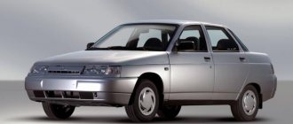
The success of the VAZ “penny” significantly influenced the development of the domestic automotive industry. On its basis, a whole series of cars was created, among which the VAZ 2104 stood out noticeably for its overall dimensions. The increase in the base led to the fact that the electrical wiring of the VAZ 2104 had its own characteristics, which will be discussed in this article.
Tip: not only different body shapes, but also different power units influenced the electrical circuits of the car. This should be kept in mind when servicing your car yourself.
Breakdowns
Most often, the contact group fails, since it is made of plastic into which copper contacts are inserted; due to the flow of high currents and weak contact between the brackets, heating occurs. Due to high temperature, the plastic is deformed and damages the contact group.
The mechanical part fails much less often, but it also happens. It becomes damaged due to prolonged use, the springs in the lock sag, the lock becomes loose, which leads to its jamming or the ability to turn it with almost any key, which reduces the car’s protection to zero.
VAZ 2104 car platform
At first, the VAZ 2102, which was an “extended” version of the classic “penny”, was assembled as a universal model with increased capacity in factory buildings. However, having identified a number of design flaws, the engineers decided to use a different platform for the station wagon.
At its core, the VAZ 2104:
- It was an extended modification of the VAZ 2105;
- Most of the parts were unified with the entire model range of the Zhiguli family;
- The rear of the car received a full-size door equipped with heated glass and a windshield wiper;
- An additional center console with function keys has appeared in the cabin.
For reference: The factory instructions offered for the new car did not always reflect the changes made during the production and modernization of the VAZ 2104.
Changing the contact group
Exploded view of the lock
Based on price considerations, replacing one contact group is less expensive:
- All our actions are repeated in principle, as in the case described above with removing the lock, you will have to remove the casing, and so on
- To avoid the widespread problem associated with mixing up contacts, it is recommended to number them before disconnecting (or mark them in some other way)
- This measure will save your nerves and time.
- Some models of locks have a locking ring in their contact group, and here we need an awl to pull it out
- It’s important not to forget to stick it in place later
- Then everything is put back together and screwed to the control column
Differences from the base model
The choice of the “five” was not accidental - in those years it was a more modern solution to the car’s design in technical terms. This was presented in every possible way in the videos of those years. But even having decided to produce a station wagon based on it, the engineers had to make changes to some components.
- Instrument panels;
- Rear blocks of side lights and brake lights;
- Injection fuel supply system for a model with a VAZ 21067 engine.
Accordingly, the VAZ 2104 engine compartment wiring diagram for the injector had design differences from the standard carburetor version.
Dashboard
An experimental panel with combined instruments was installed on a VAZ 2104 car.
In particular, a single device (in the diagram under No. 7) consisted of:
- Low battery level indicator;
- Fuel level indicator in the gas tank, combined with a warning lamp;
- Engine oil pressure warning lamp;
- Coolant temperature gauge with level indicator lamp in the expansion tank.
Illumination of the instrument board, how the panel is arranged
Any modern car must have lighting for both the instrument panel and other buttons and switches located on the car’s dashboard. Illumination of the ignition switch is a very common occurrence in imported cars. Our manufacturers have not thought of this, so many drivers improve their iron horse on their own. Such lighting will give your car a special charm at night, and it’s convenient to see where to insert the key.
It is not difficult to install, and its service life is very long. The most important thing is that when choosing such lighting you don’t need to invent anything. Car dealerships, as a rule, sell standard types of backlights that have only one bulb and can only shine at a point. For VAZ cars, they began to produce ready-made elements for illuminating the ignition switch, which are conveniently mounted and do not require alterations or cutouts in the plastic of the car’s steering column.