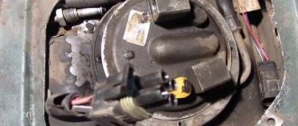
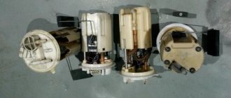
Replacing the fuel pump on VAZ-2113, 2114, 2115
It is commonly said that the heart of a car is its engine.
This is not entirely true, because a motor is an engine, that is, it should rather be compared to muscles, but a heart can, without a doubt, be called a gas pump. As soon as he stops, the car itself stands dead. You can drive to the nearest service center with three cylinders, a broken radiator, and a non-working generator, if you know how to do it. Without a fuel pump - only with a tow truck or on a cable. True, there are stories about how some craftsmen were able to connect a glass washer reservoir to the fuel system by pouring gasoline into it, but this is such an exotic thing that repeating it is dangerous both for the life of the car and for your own.
Popular breakdowns
Problems with the fuel pump can occur for several reasons. Therefore, your first priority is to determine the source of the problem. These may be:
If one of these elements fails, it can stop the normal functionality of the entire module.
Let us consider the situations with each of the specified elements of the fuel module in more detail.
Pressure
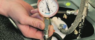
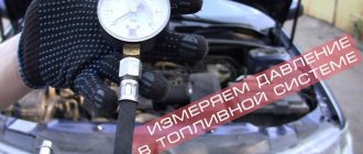
What exactly is a fuel pump? This is an element of the fuel system that allows fuel to pass through due to pressure. Therefore, if you take pressure measurements, you can get answers to many questions.
Let's give an example of normal pressure readings when checking in certain modes.
Pinout of fuel pump VAZ 2107
1 – radiator fan drive motor; 2 – mounting block block; 3 — idle speed sensor; 4 – engine ECU; 5 – potentiometer; 6 – set of spark plugs; 7 – ignition control unit; 8 – electronic crankshaft position sensor; 9 – electric fuel pump; 10 – indicator of the number of revolutions; 11 – lamp for monitoring the health of electronic systems and the brake system; 12 – ignition system control relay; 13 – speedometer sensor; 14 – special factory connector for reading errors using the BC; 15 – injector harness; 16 – adsorber solenoid valve; 17, 18, 19,20 – fuse box for repairing the mounting block that protects the injection system circuits; 21 – electronic fuel pump control relay; 22 – electronic relay for controlling the exhaust manifold heating system; 23 – exhaust manifold heating system; 24 – fuse protecting the heater circuit; 25 – electronic air sensor; 26 – coolant temperature control sensor; 27 – electronic air damper sensor; 28 – air temperature sensor; 29 – pressure control sensor and low oil pressure lamp.
You can check the fuel pump on a VAZ 2107 simply by checking the voltage at its connection block with a tester. The presence of voltage will indicate a malfunction of the electric motor. Instead of a tester (multimeter), you can use a test lamp to diagnose a malfunction.
In the absence of one, this can be done by disconnecting the connection block for the fuel pump and fuel level control and applying voltage with wires from the battery to the place where the gray wire is connected +12 and to the place where the black wire is connected - minus. A humming pump will indicate a faulty fuse, power circuit or ECU.
Checking the electrical circuit
Unlike a carburetor engine, where the fuel pump is mechanically driven, on the injection VAZ 2110/2112 a special relay and fuse are responsible for the operation of this device. Therefore, before moving on to diagnosing the pump itself, it is necessary to check the indicated elements. If any one of them is faulty, the pump will not work at all.
Turn on the ignition without starting the engine and listen. When the fuel pump is running, it emits a characteristic “whistle” when started. If it is not there, it means that either the pump itself has failed, or one of the elements of its power supply circuit has failed.
The pump relay and fuse are located in an additional mounting block located inside the vehicle's center console. It can be accessed by removing the plastic trim (near the front passenger's left foot). It is secured with several screws. Under the cover you will find three relays and three fuses. Typically, the fuel pump circuit protection elements are located centrally.
Removing and installing the fuel pump
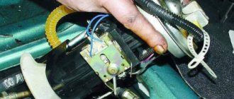
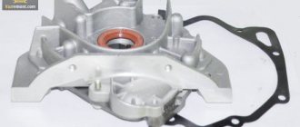
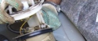
Removing and installing the fuel pump is a simple operation. The fuel pump, together with the gaskets, is mounted on two studs and secured with nuts, which must be unscrewed with a 13 mm wrench. To remove the fuel pump, you need to disconnect the supply and discharge fuel lines, unscrew the fuel pump mounting nuts, remove the spring washers, and then the fuel pump itself.
When removing it, be careful, as you can damage the thin gasket, which often sticks to both the pump and the thick heat-insulating gasket. The thermal insulation gasket itself, as a rule, can be easily removed by hand without the use of any tools. In the worst case, make it easier to remove by lightly tapping it with the handle of a screwdriver. Do not forget also that under the thick thermal insulation gasket there is another thin installation gasket, which is also a sealing gasket.
Installing a repaired fuel pump has its own characteristics. First of all, install a sealing gasket A with a thickness of 0.70-0.80 mm, and then a heat-insulating one. Next, install a thin gasket B with a thickness of 0.27–0.33 mm.
With such a set of gaskets between the fuel pump body and the cylinder block, the minimum output of the pusher (its inner end touches the back of the cam) should be in the range of 0.8-1.3 mm. This dimension (d) can be easily checked by installing spacers and a pusher (rod). If the pusher protrudes from the gaskets by an amount less than 0.8 mm, then gasket A is replaced with gasket B with a thickness of 0.27-0.33 mm.
In the case where the pusher protrudes more than 1.3 mm, instead of gasket A, it is necessary to install a thicker gasket type C with a thickness of 1.20-1.30 mm. It should be clarified that a gasket with a thickness of 0.27-0.33 mm should always be installed between the fuel pump body and the heat-insulating gasket.
Video instructions for replacement
› Logbook › 076: Replacing the fuel pump motor. PEKAR. As it turned out, it was completely in vain)
So, where did it all start?
We left our daughter with my grandmother and went with my wife to the store. As soon as I parked, I was about to turn off the car, waiting for the fan to stop, when the car suddenly stopped on its own.
Not understanding anything, I try to start it. Nevermind. It twists and turns, but does not grab at all. After thinking a little, I sent my wife home))
My first thought was that the timing belt might have jumped... since I recently took it off/on when replacing the pump. I took off the cover and rolled the car forward in gear a little. The marks matched. So it's not a belt)
I replaced the spark plugs with spare ones, it didn't help)
I checked for the presence of a spark, brought the wire with a spark plug to the body, while a random passerby turned the starter. There is a spark.
I started thinking about the fuel supply. I changed the fuel pump motor a year ago, or almost exactly 20,000 km. back. The fuel pump was the cheapest, so it could have been that))
In short, after some time, when turning the key, the fuel pump stopped buzzing altogether.
During the investigation, I found wires in the cabin that were not in very good condition))
Along the way, I changed all the fuses and relays on the ECU, the fuel pump, and apparently on the fan too))
Zero effect. The fuel pump does not pump.
And then, like a brilliant diagnostician, I conclude that the problem is in the fuel pump and the motor needs to be replaced)) As it turned out later, I was wrong ((
Sequence of repair work
Installing the cylinder head
Also need a new head gasket and valve cover gasket. Having all this, you can begin the renovation. The sequence of actions for repairs is as follows:
- The car is placed in the garage, the gearbox is set to neutral, and chocks are placed under the rear wheels. The first thing that is done after setting up the car is to de-energize the on-board network by disconnecting the “-” terminal from the battery.
- The pressure in the fuel system is relieved. For this purpose, there is a control valve on the fuel rail in the form of a regular tire valve. You need to place a container under this valve and clamp the spool. When the pressure is released, gasoline will leak out. You will also need to drain the coolant using drain plugs.
- On the engine, you need to set the piston of the 1st cylinder to the TDC position. To do this, remove the protective cover of the timing belt and rotate the crankshaft until the marks on the pulley, camshaft and flywheel match.
- The next step is to remove the valve covers. To do this, all pipes, the throttle drive rod, the accelerator drive bracket and the valve cover mounting nuts are disconnected from the cover fittings.
- The exhaust pipe of the exhaust gas removal system is disconnected from the exhaust manifold. These works are carried out under the car.
- The wiring is disconnected from the mass flow sensor, the air supply pipe to the throttle assembly is removed, after which it is completely dismantled along with the air filter housing.
- Then you need to disconnect from the head all the elements suitable for the head - pipes of the cooling system of the throttle assembly, vacuum booster, throttle drive linkage, ground wires, bracket for the exhaust manifold supply pipe.
- The intake manifold strut mounts are also loosened, and the struts themselves are removed. Next, the wiring is disconnected from - oil pressure sensors, coolant temperature and throttle position sensors, XX regulator, injectors, high-voltage wires from spark plugs.
- Then the timing belt is removed. Before this, you need to once again check the alignment of the marks on the crankshaft pulley and the timing gear. After this, the belt tension is loosened and it is removed from the timing gear.
- To remove the camshaft gear, you will need to fix it through the technological holes and unscrew the fastening bolt. You need to remove it from the shaft carefully so as not to lose the key. After this, you will need to remove the rear cover, located behind the removed gear, from the head and block.
- The cooling system pipes are removed from the head along with the thermostat from the head, as well as the rest of the wiring. The fuel supply and drain pipes are also disconnected.
- All that remains is to unscrew the head bolts. But to do this, they must first be weakened, and in a strictly defined order. And only after relaxation do they completely unscrew. If disassembly is done correctly, after removing the bolts, you can remove the head and remove the damaged gasket. At this point, the first part of the repair is considered complete.
Before you begin the process itself, you need to decide on the necessary tools. So, what will you need: a ratchet and sockets for 17, 19; screwdrivers with flat and Phillips tips; a set of keys and the gasket itself.
Now that everything is prepared, you can start working directly. In order for the manifold to be removed without any problems and rusted bolts not to create trouble, everything must be lubricated with WD-40 before performing the operation. It is advisable to do this several times. Before performing the operation, you need to think again, weigh everything and calculate your strength.
Symptoms of a problem
A malfunction of the fuel pump of VAZ 2114/2115 cars can be diagnosed by the following symptoms:
- when the ignition is turned on, there is no sound of the pump running;
- the engine does not start or starts with difficulty;
- the power unit is unstable at idle, the speed “floats”;
- “dips” appeared during acceleration;
- the motor has lost power.
The same signs also appear when other elements of the fuel system malfunction.
Before you begin diagnosing or replacing the fuel pump, you should make sure that:
- the fine fuel filter is not clogged (it is changed every 7 thousand kilometers);
- the injectors and fuel pressure regulator are operating normally;
- The sensors for mass air flow, throttle position, and oxygen quantity are working properly.
If the detected malfunction is accompanied by the lighting of the “CHECK” lamp on the dashboard, you should set the error code and decipher it.
Which fuel pump to install on a VAZ 2114
On the VAZ 2114 and others of this family, they are installed from Bosch or Denso, since the original fuel pump only comes complete with a module (article 21102-1139009-02). Other manufacturers may be preferred only for reasons of economy.
| Manufacturer | vendor code | Average price, rub. |
| SAT | STFP06 | 799 |
| MEAT DORIA | 76416 | 1056 |
| DENSO | DFP0105 | 2504 |
| BOSCH | 580453453 | 2899 |
Tool required for work
- 10mm wrench;
- Screwdrivers “+” and “-“;
- Construction hair dryer;
- Pliers;
How to Test a Mechanical Fuel Pump
To check a mechanical fuel pump, you will need the following tools and tools:
- screwdriver with Phillips bit;
- slotted screwdriver;
- key (head) 10;
- key to 13;
- 2 clean dry plastic bottles with a volume of 2 liters;
- a piece of hose (50 cm) of the same diameter as the fuel one;
- 1–1.5 liters of gasoline;
- caliper (ruler);
- stopwatch (clock).
Let's start with performance. A working VAZ 2110 mechanical fuel pump with a obviously clean filter should pump at least 1 liter of fuel per minute. The verification algorithm is as follows:
- We lift the hood and find the pump.
- Using a screwdriver, unscrew the screw of the pump outlet hose clamp. Loosen the clamp and remove the hose from the pump fitting.
A performance test involves measuring the amount of fuel pumped over a specified period of time.
If the amount of fuel pumped in 1 minute is less than 1 liter, the fuel pump is faulty
If the amount of fuel pumped per minute is less than a liter, the pump is faulty. The reasons for this may be:
- faulty valves;
- rupture of one or more membranes;
- clogging of the pump grid;
- wear of the drive rod (pusher).
We carry out further checks in the following order:
- Disconnect both fuel line hoses from the pump.
Disconnect the inlet and outlet hoses
When you press the manual pumping lever, you should feel a vacuum at the inlet fitting, and a pressure of air at the outlet
Design features of the engine on the VAZ-2114
Valve cover gasket replacement process
Before moving directly to the process, you need to know some structural elements of the VAZ-2114 engine.
The valve cover gasket is located directly under the cover itself and this can be clearly seen in the diagram below.
So, first, let's look at what the engine consists of:
Diagram of internal combustion engine components
| № | Detail number | Part name |
| 1 | 2108-1003298 | screw |
| 2 | 2108-1003278-01 | Washer |
| 3 | 2108-1003277-01 | Sleeve |
| 3 | 2108-1003277-02 | Sleeve |
| 4 | 2108-1003274 | Cover pin |
| 5 | 2111-1003260 | Cylinder head cover |
| 6 | 2108-1003271 | Bolt M12x1.25x135 |
| 7 | 2108-1003265 | Washer |
| 8 | 14328201 | Plug 10 cup |
| 9 | 14329101 | Plug 30 cup |
| 10 | 1118-1003011 | Cylinder head |
| 11 | 2101-1002042 | Sleeve |
| 12 | 14329201 | Plug 36 cup |
| 13 | 10158601 | Plug 16 spherical |
| 14 | 11183-1002011-10 | Cylinder block |
| 15 | 14234330 | Bolt M10x1.25x65 |
| 16 | 2108-1003284-10 | Ring sealing |
| 17 | 2111-1003284 | Ring sealing |
| 18 | 2111-1003286 | Bolt |
| 19 | 2111-1003288-10 | Stub |
| 20 | 10725911 | Nut M6 low |
| 21 | 11197773 | Conical spring washer 6 |
| 22 | 13541221 | Hairpin M6x22 |
| 23 | 2108-1003270-10 | Cover gasket |
| 23 | 2108-1003270-11 | Cylinder head cover gasket |
| 24 | 21083-1003020-10 | Head gasket |
| 24 | 21083-1003020-11 | Head gasket |
| 25 | 2112-3855020 | Knock sensor |
| 25 | 2112-3855020-01 | Knock sensor |
| 25 | 2112-3855020-02 | Knock sensor |
| 25 | 2112-3855020-03 | Knock sensor |
| 26 | 2101-1002040 | Sleeve |
Design features of fuel pumps for carburetor and injection fuel injection systems
Mechanical fuel pumps, which were installed on the first modifications of the VAZ 2110/2112, have a simple design. It is based on a set of membranes made of special rubberized fabric that is resistant to the chemical action of gasoline. The pump body has two valves: inlet and outlet. The membranes are driven by a rod (pusher). It is driven by a cam mechanism rotated by a camshaft.
Such a mechanical fuel pump can serve for decades until the drive rod wears out or one of the membranes breaks. And even then, if this happens, you can replace these elements in half an hour.
The first modifications of the VAZ 2110 with a carburetor injection system were equipped with mechanical fuel pumps
Fuel pump device
Modern cars use two types of fuel pumps - mechanical or electric. The former are used in carburetor engines, the latter in injection engines.
The mechanical pump is usually installed on the body of the gas tank, while the electric pump is installed inside the tank. Some automakers use both types of pumps at once.
Mechanical pump
The mechanical fuel pump is quite large. Its main elements are:
- fuel chamber;
- inlet valve;
- release valve;
- diaphragm;
- diaphragm return spring;
- drive lever;
- camshaft;
- fist.
When power is applied to the fuel pump, the lever begins a repetitive up and down motion. Due to these movements, the diaphragm moves, and gasoline flows first into the pump and then into the engine.
This is how fuel is supplied in carburetor-type engines. Since the distance between the carburetor and the fuel pump is usually small, such devices can supply fuel even at minimal pressure.
A mechanical fuel pump is usually installed on the body of the gas tank
Electric pump
Electric fuel pumps are small in size and have a simple design. Inside the pump housing are:
- chamber for gasoline;
- inlet valve;
- release valve;
- additional solenoid valve;
- diaphragm;
- diaphragm return spring;
- core;
- electrical contacts.
The main element of an electric pump is the core. Due to the additional valve, it performs reciprocating movements and opens the valves for fuel inlet and outlet. Such a pump only works when the fuel pressure in the system is high and gets very hot while the car is moving. For more efficient cooling, it is usually mounted in the gas tank.
The electric fuel pump is small in size and simple in design.
How does a fuel pump work?
The fuel pump is powered by the power unit. When the engine starts, the on-board computer signals the fuel system about the need to supply fuel. Electricity is supplied from the engine to the fuel pump, and a small motor inside the pump creates the necessary pressure in the system. In the first few seconds after starting the car, you can hear the fuel pump humming as it pumps gasoline.
A certain amount of fuel enters through the inlet valve into the pump chamber, then through the outlet valve into the fuel filter. There, the fuel is cleaned of dirt and impurities and sent to the engine. The fuel pump turns off automatically, along with the engine.
