Hi all! As I wrote a long time ago, I wanted to improve the power supply to the ignition module. This idea came after I accidentally came across an article by user mcsystem, for which I thank him. An additional fuse box was even installed, but another problem arose. My character does not allow me to get involved in the factory wiring; I like it when everything can be returned to stock without major problems. Therefore, I wanted to find the ignition module connectors and make a removable system. The connector that is inserted into the module was found in the store without any problems, but the mating part is more difficult to find. It was decided to rip the connector out of the dead module. But finding a dead module in my city turned out to be problematic. And paying 2 kilo rubles for a new one is stupid because of the connector. That's why the matter stopped.
But the world is not without good people, and exclusive33rus sent me a dead module, for which I thank him very much! At the factory I took two wires with a cross-section of four squares, and real four squares, and not those funny wires that are sold in the store. Well, at the same time, two tips, with holes for 6 and 8 mm, since I still didn’t know which one I would put.
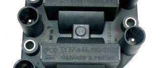
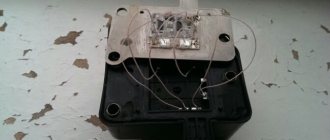
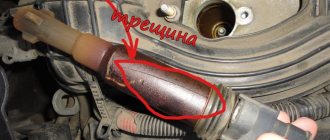
I tore the connector out of the module, measured the required length of wires and began soldering. And here’s a surprise - the metal that connects everything in the module is not soldered with anything! The metal is very shiny, like lead, and brittle to bend like aluminum. I was upset, but there was nothing to do, I had to think further. And then the OBD-II diagnostic KKL cord caught my eye, and I saw that the pins were the same! I disassembled it, found unused pins, heated them with a soldering iron and pulled them out. I pulled out solderless pins of unknown metal from the connector and melted the pins from the cord. I soldered it and decided to fill the soldering area with supermoment and soda. It was with great grief that I found superglue at home, but, as they say, it wasn’t diarrhea—it was scrofula, and there was no soda at home. It seems like such a thing that everyone has had for years and practically never used, but I don’t have it. It was late, the shops were already closed, there was no way to buy anything. And then I remember that on the balcony there is soda ash, which I used to make printed circuit boards using the photoresist method. I try it with superglue - everything is great! I fill the connector, and am faced with the second problem - the wire did not fit into the connector, so about five centimeters to the connector I had to slightly reduce the cross-section, from four squares it dropped to about 2.5, but I thoroughly tinned everything, so the losses will be minimal. I put everything in the corrugation and leave the wiring until daylight; it’s not very convenient to install in the dark.
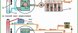
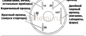
As you can see, there is a relay in the circuit. Those who understand electrics, I think, understood immediately, but for the rest I’ll explain what I can do. So, there are four wires going to the module, two signal wires, through which the ECU gives the command to give a spark to the cylinders (1-4 and 2-3, respectively), and two 12 volt power supply. So the signal signals go directly from connector to connector, but the module’s power now goes to the relay, through which +12 volts goes directly from the battery with a thick wire.
Pinout, connection diagram and check of the VAZ ignition coil
Today we will look at the design and diagrams of ignition systems for VAZ cars of all major models. Since carburetor versions of VAZ are practically history, we will dwell in detail on the ignition systems of injection cars. Their ignition system is based on an electronic ignition module. We also recommend that you carefully consider the choice of spark plugs and the quality of high-voltage wires, because the quality of the spark and, accordingly, the operation of the ignition system as a whole will depend on them. The information is intended as a reference guide for self-repairing a car.
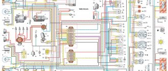
VAZ-2111 diagram
The free collection of materials to help auto electricians contains all the necessary documentation on the electrical equipment of the VAZ-2111 car - general circuit diagram, switching system, electronic engine control module, relay block with fuses and other components. The VAZ 2111 car is a station wagon (production from 1998 to 2014), which is a modernized concept of the rear-wheel drive VAZ-2104. Here the wiring diagram for the injector and a number of other components have been slightly changed, as can be seen from the electrical diagrams and harnesses.
Pinout and diagram of the VAZ ignition coil
Pinout of ignition coil modules for various car models of the VAZ family:
Ignition VAZ 2101
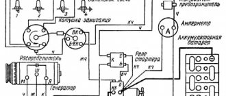
1 – generator; 2 – ignition switch; 3 – ignition distributor; 4 – breaker cam; 5 – spark plugs; 6 – ignition coil; 7 – battery.
Ignition VAZ 2106
1 – ignition switch; 2 – fuse and relay block; 3 – EPHH control unit; 4 – generator; 5 – solenoid valve; 6 – microswitch; 7 – spark plugs; 8 – ignition distributor; 9 – ignition coil; 10 – battery.
Ignition VAZ 2108, 2109
Ignition VAZ 2110
Ignition VAZ 2111
Ignition VAZ 2112
Ignition VAZ 2114
Diagram of a non-contact ignition system: 1 – non-contact sensor; 2 – ignition distributor sensor; 3 – spark plugs; 4 – switch; 5 – ignition coil; 6 – mounting block; 7 – ignition relay; 8 – ignition switch.
Repair and cleaning manual for the Lada 2110 carburetor, do-it-yourself steps for removing and installing the carburetor from the Lada 2111 car, instructions for disassembling and assembling parts of the Lada 2112 carburetor. Repair of the carburetor power system of the VAZ 2111, VAZ 2112, VAZ 2110. Maintenance of the engine of the Lada 2112 car. Instructions for repairing the cooling system, exhaust gas, power supply of Lada 2111. Features of the 8- and 16-valve engine of Lada 2110. Operation of the main components and assemblies of the engine
Diagram of a contactless ignition system 1 – battery 2 – generator 3 – plug connector 4 – ignition switch 5 – distributor sensor 6 – switch 7 – spark plugs 8 – ignition coil Ignition system – contactless or microprocessor. This section discusses the contactless ignition system. It consists of a distributor sensor, a switch, a VAZ 2112 ignition coil, spark plugs, an ignition switch and high and low voltage wires.
Scheme for checking the Hall sensor on a car 1 - ignition distributor sensor 2 - voltmeter with a scale limit of at least 15 V and internal resistance of at least 100 kOhm 3 - view of the plug connector of the ignition distributor sensor
Sensor-distributor 40.3706 a – device b – operation diagram of the centrifugal regulator 1 – coupling 2 – housing 3 – vacuum regulator 4 – vacuum regulator rod 5, 7 – vacuum regulator covers 6, 12 – springs 8 – fitting for vacuum supply 9 – diaphragm 10 – centrifugal regulator 11 – non-contact sensor 13 – driven plate of the centrifugal regulator with screen 14 – roller with drive plate of the centrifugal regulator 15 – weights 16 – oil seal 17 – cover 18 – rotor 19 – protective screen 20 – holder of the front roller bearing assembled with the support plate sensor 21 – washer for fastening wires 22 – sensor support plate with bearing Ignition distributor sensor type 40.3706 or 40.3706-01, four-spark, unshielded, with a control pulse sensor (Hall VAZ 2112) and built-in vacuum and centrifugal ignition timing regulators. The distribution sensor performs two main functions: firstly, it sets the moment of spark formation depending on its initial setting, the number of revolutions of the crankshaft and the load on the engine, and secondly, it distributes high voltage pulses (“spark”) among the cylinders in accordance with the order of their work. For this purpose, a rotor (runner) mounted on the distributor sensor roller is used. In order to avoid mistakes during assembly, the slider and the cover of the sensor-distributor are installed on the sensor-distributor in only one position, as well as its roller. The slider contains a 1 kOhm noise suppression resistor. You can check the functionality of the Hall sensor of the VAZ 2111 by assembling the circuit shown in the figure. Slowly rotating the ignition distributor shaft, monitor the voltmeter readings. The voltage should change sharply from the minimum (no more than 0.4 V) to the maximum (no more than 3 V less than the supply voltage). If a steel screen with slots touches the sensor (determined by slight jamming or a scratching sound when the roller rotates, as well as after partial disassembly of the sensor-distributor), check the axial play of the roller (no more than 0.35 mm, adjusted by selecting washers) and the fit of the screen on roller If necessary, replace the roller assembly. A faulty Hall sensor in a VAZ 2110 cannot be repaired (except for a break in the wires between the sensor itself and the block on the sensor-distributor housing). You can roughly assess the serviceability of the vacuum regulator directly on the car. With the engine running, disconnect the vacuum hose leading to the regulator from the carburetor fitting. If you now create a vacuum in the hose (you can use your mouth), the engine speed should increase, and when the vacuum is removed, it should decrease again. The vacuum should remain for at least a few seconds if the hose is pinched. You can visually verify the functionality of the vacuum regulator by partially disassembling the ignition sensor-distributor (see Removing and disassembling the ignition sensor-distributor) and applying a vacuum to the inlet fitting of the regulator. In this case, the plate with the Hall sensor should rotate at an angle of 7±1°, and when the vacuum is removed, return back without jamming. Precise checking and adjustment of the vacuum and centrifugal ignition timing regulators of the VAZ 2110 is carried out on special stands. It is not recommended to do this at home. If the vacuum regulator fails, it should be replaced; if the centrifugal regulator fails, the sensor-distributor should be replaced. A switch type 3620.3734 or 76.3734 opens the power supply circuit of the primary winding of the ignition coil, converting the sensor control pulses into current pulses in the ignition coil. The switch is checked using an oscilloscope using a special method; it is not repairable. Do not disconnect the switch connector while the ignition is on - this may damage it (as well as other components of the ignition system). Ignition coil - type 3122.3705 - dry, with a closed magnetic circuit, or type 8352.12 - oil-filled, with an open magnetic circuit. Data for testing: resistance of the primary winding at 25°C – 0.43±0.04 Ohm (3122.3705) or 0.42±0.05 Ohm (8352.12), secondary winding – 4.08±0.4 kOhm (3122.3705) or 5±1 kOhm (8352.12). Insulation resistance to ground is at least 50 MOhm. Spark plugs - type A17DVR, or A17DVRM, or A17DVRM1, or their imported analogues (with noise suppression resistance 4-10 kOhm). High-voltage wires – with a distributed resistance of 2550±270 Ohm/m. Do not touch high-voltage wires while the engine is running - this may result in electrical injury. It is also prohibited to start the engine or allow it to operate with an open high-voltage circuit (removed wires or sensor-breaker cover) - this can lead to burnout of the insulation and failure of the electronic components of the ignition system. As an exception, a short-term check of the ignition system “for spark” is possible, and the contact of the high-voltage wire being tested must be securely fixed at a distance of 5-10 mm from the vehicle ground. Do not hold the wire with your hands or tools (even with insulated handles). The EPHH Lada 2110 control unit turns off the solenoid valve when the crankshaft rotation speed increases to 2100 min-1 and turns it on when it decreases to 1900 min-1, if the carburetor limit switch is shorted to ground (the gas pedal is released). When the gas pedal is pressed (the switch is open), the valve is turned on regardless of the crankshaft speed. Power is supplied to the control unit only when the ignition is on, so when the ignition is turned off, the valve is also turned off (regardless of the position of the VAZ 2110 carburetor limit switch).
Diagram of the carburetor solenoid valve control system 1 - ignition switch 2 - ignition coil 3 - control unit 4 - solenoid valve 5 - carburetor limit switch A - to power sources To check the operation of the control unit, connect a voltmeter, as shown in the figure below (valve operation can be determined and by its click when the ignition is turned on, without a voltmeter). We disconnect the wire from the limit switch of the VAZ 2111 carburetor and short it to ground. We start the 2110 engine and, gradually increasing the crankshaft speed, monitor the voltmeter readings. After starting the engine, it should show at least 10 V (the valve is open), and at a crankshaft speed of about 2100 min -1, the voltage should sharply drop to a value of no more than 0.5 V (the valve should close). After this, we slowly lower the engine speed; at a crankshaft speed of about 1900 min -1, the voltage should increase abruptly to its previous value (the valve should open). We set the speed within 2200-2300 rpm (the valve is closed) and disconnect the VAZ 2111 carburetor limit switch wire from ground - the valve should open.
Diagram for checking control unit 1 - control unit 2 - voltmeter A - to the vehicle wiring harness
How to check the ignition coil of a VAZ
If the ignition coil is faulty, the engine will not start. A characteristic sign of a faulty coil is its increased temperature when the ignition is turned off. This is easy to determine by touch.
Signs of a faulty ignition module may include the following:
- hesitant engine starting or failure to start;
- failures during sudden changes in speed;
- high fuel consumption;
- two cylinders do not work, the engine is feverish;
- lack of dynamics;
- a sharp drop in power;
- drop in power and thrust after warming up.
These symptoms may not only be caused by the ignition module. To determine the malfunction, it is enough to spend a few minutes diagnosing spark plugs, high-voltage wires and caps. This will eliminate the remaining elements of the ignition system and make sure that it is the ignition module that is faulty.
Checking the ignition coil is performed in one of 2 ways. The simplest one is to remove the central wire from the breaker-distributor, bring it to the motor housing and turn it with the starter, and a running spark should appear. After this, we check the energy supply to a separate spark plug, for which we unscrew the working spark plug, bring its contact to ground and attempt to start the engine. In this case, the spark should come from the wire to ground. If it is absent, the reason will be a malfunction of a system element such as the ignition coil.
To check the module in the second way, we only need a multimeter, then follow the step-by-step instructions:
- We check the power supply and the presence of pulses supplied from the ECU. We check the power between the central terminal (15) of the wire block connected to the module and the engine ground. When the ignition is on, the voltage should not be less than 12 V. Otherwise, either the battery is dead or the ECU does not work.
- We check the pulses from the ECU on the wiring block. We install one tester probe on connector 15, the second on the far right, then on the far left. The assistant cranks the engine with the starter, and at this time we record short-term voltage surges with a tester. If there are no impulses from the ECU, it is he who is to blame.
- We check the resistance on the secondary windings of the coils. We put the tester in resistance measurement mode and measure it at the high-voltage terminals of the module cover. Between pins 1 and 4 and pins 2-3, the resistance should be 5.4 kOhm. Otherwise, the module must be replaced.
- We check the resistance of the primary windings between contacts 15 and the rightmost, then the leftmost terminals. Nominal - 0.5 Ohm. Deviation is not allowed.
- Check the module for a short circuit. In ohmmeter mode, install one multimeter probe on the central terminal, the second on the metal body. There shouldn't be any resistance. If the device detects at least some resistance (other than unity or infinity), the module must be replaced.
How to disassemble the ignition module of a VAZ 2110
Many car owners are faced with the problem that their car won't start. If it suddenly turns out that there is no high voltage on the cylinders (only on one or several at a time) or the control lamp does not light up, there is no spark, then the engine will not work. The ignition module may be faulty. It's not always worth rushing to the shops in search of something new.
Owners of a VAZ-2110 car are offered an alternative - to repair the ignition module themselves. The main thing is to have basic knowledge of auto electricians and the ability to understand circuits and contacts. It's also a good idea to be able to use a digital multimeter in your work.
Knowledge of its components is also required to disassemble the ignition module. This is a pair of ignition coils designed to excite high voltage pulses and a two-channel switch. Basically, high-frequency pulses can disappear in the 2nd and 3rd cylinders. First, you will need to disassemble the ignition module. The high-voltage cables are disconnected, then the VAZ-2110 ignition module itself is removed.
The essence of the repair is as follows:
- You will need a straight screwdriver to open the aluminum plate.
- Looking at the insides of the module, it may seem that everything is very complicated. You should pay attention to the printed circuit board, which is coated with transparent silicone. The sealant has been removed. To make the wires with which the board is connected to the contacts of the connectors and coils, aluminum is used that is too soft, so they become unusable. Such threads break and are thrown away. What should I put in place?
- You will need a computer mouse, which will need to be disassembled. All you need is interlocking threads.
- The ignition module circuit includes two L497D1 switches manufactured by SGS-THOMSON and two fairly powerful transistors. The contacts are made of aluminum, so soldering aluminum requires a special flux.
- First, the wires are soldered to the board itself. The collectors are coated on top with a special metal that cannot be welded. Therefore, before soldering the wires, the plate is removed from the metal.
- The plate is then placed on the plate and heated to one hundred and eighty degrees, which distributes the heat throughout the plate. It is important that when the soldering iron comes into contact with the plate, heat does not dissipate from it.
- Now you can proceed directly to soldering the wires to the module contacts. Try to keep the strands as short as possible. Next, take varnish (the varnish you use to paint your nails will also work) and cover the adhesions with it for insulation.
- Next you need to check the ignition module. It must be feasible. And the final touch: the inner surface is covered with a self-sealing film, after which the assembly is completed. The threads should be loose and not pinched.
The work is not that difficult, it is accessible to anyone who knows how to work as a welder and has basic knowledge of electronics.
If after repair it turns out that the cause of the malfunction was different, you need to find this reason or go to the store for a new module.
Connecting and replacing VAZ short circuit
The procedure for removing and installing the ignition coil on old VAZ models:
- First, disconnect the central high-voltage wire leading to the distributor (ignition distributor).
- Disconnect all power wires from the coil contacts. Since they are fastened with nuts, you will need an 8 wrench for this.
- If you don’t know which wires to connect to which connector later, it’s better to immediately remember or mark them somehow, so that later during installation you can connect them correctly.
- Unscrew the coil housing. It is attached to a clamp (clamp), which is pressed to the car body with two nuts.
- After the work has been done, you can remove the ignition coil and replace it if necessary.
For new type VAZ cars:
- We remove the “minus terminal” from the battery.
- Remove the top protective cover of the engine. If the engine volume is 1.5 liters, then this part is missing and this step is skipped.
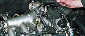
- We remove the high-voltage wires from the coil.
- Now, using a 13mm wrench, unscrew the two fasteners.
- Using a 17mm wrench, loosen one bolt securing the coil.
- We take out the module.
- Use a hexagon to unscrew the coil from the holder.
- Assembly is carried out in reverse order.
Particular attention should be paid to the connection, since high-voltage wires must be located in the strict order provided for by the design. If this is not done, the car will stall or the engine may not start at all.
Replacing the ignition coil on a VAZ is quite simple. Even a novice motorist can do this in his garage, and if everything seems too complicated, contact a car service center. Particular attention should be paid to the choice of product, since this will determine how well the engine and ignition system will work.
VAZ models 8 and 16 valves
Despite the similarity in engine design, the ignition system of the 1.5-liter injection 16-valve engine differs from the 1.6 16-valve engine. The 1.6 liter engine uses an electronic contactless ignition system with individual coils on each spark plug. Therefore, there was no need for an ignition module. Such a system is more reliable and cheaper to operate, since if one coil fails, there is no need to replace the entire module.
The 16-valve 1.5-liter VAZ 2112 injection engine used the same non-contact ignition system as the 8-valve engine, but a different ignition module was installed. Its catalog number is 2112-3705010. The design of the module remains the same - two ignition coils (for cylinders 1-4 and 2-3) plus switch keys in a single block. The spark is supplied to the cylinders in pairs using the idle spark method. This means that sparking occurs in two cylinders simultaneously - in one on the compression stroke (working spark), in the second on the exhaust stroke (idle spark).
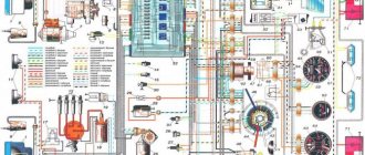
Electrical diagram of VAZ-2112
Designations: 1 – Headlight, 2 – Klaxon, 3 – Main radiator fan, 4 – Starter, 5 – Battery, 6 – Generator 2112, 7 – Gearbox limit switch (reverse), 8 – Actuator in the front passenger door, 9 – Power window enable relay, 10 – Starter relay, 11 – Heater fan, 12 – Electric heater partition drive, 13 – Main pump, 14 – Washer reservoir sensor, 15 – Driver’s door actuator, 16 – Front passenger window selector, 17 – Unlock button fifth door, 18 – Heater fan resistance unit, 19 – Main wiper motor, 20 – Driver’s window lift selector, 21 – Front passenger’s window lift motor, 22 – Central locking, 23 – Exterior light switch, 24 – Brake fluid leakage sensor, 25 – Pump additional, 26 – Driver's window lift motor, 27 – PTF on indicator, 28 – PTF switch, 29 – Dashboard, 30 – Heated glass on indicator, 31 – Heated glass switch, 32 – Steering column selector switch, 33 – PTF relay, 34 – Ignition switch, 35 – Main fuse block, 36 – Illumination of heater controls, 37 – Hazard warning button, 38 – Heater control controller, 39 – Glove compartment lighting, 40 – Glove compartment lid end cap, 41 – Cigarette lighter, 42 – BSK – display unit, 43 – Ashtray illumination, 44 – 12V socket, 45 – Instrument lighting switch, 46 – Actuator in the right rear door, 47 – Right rear passenger window selector, 48 – Clock, 49 – Right rear passenger window motor, 50 – Brake limit switch (closed – pedal is pressed), 51 – Left rear passenger window motor, 52 – Left rear passenger window selector, 53 – Actuator in the left rear door, 54 – Turn signal, 55 – Handbrake limit switch (closed – handbrake on), 56 – Rear wiper motor , 57 – Navigator's lamp, 58 – Interior lamp, 59 – Temperature sensor in the heater, 60 – Limit switch for the open front door, 61 – Limit switch for the open rear door, 62 – Trunk light, 63 – Rear optics (on the body), 64 – Rear optics (on the fifth door), 65 – License plate illumination.
The letters indicate the terminals to which it is connected: A – Front speaker on the right, B – Radio, C – Injector harness, D – ESD diagnostic connector, D – Front left speaker, E – Diagnostic connector for the heater controller, G – Rear right speaker, W – Rear left speaker, I – BC connector, K – glass heater thread, L – fifth door actuator, M – Additional brake light.
Wiring diagram VAZ-2112 injector 16 valves - full view
Ignition coil diagram for VAZ 2112 16 valves
To do the job you will need a multimeter.
1. We prepare the car for work (see “Preparing the car for maintenance and repair”).
2. Remove the decorative trim of the engine (see “Decorative trim of the engine - removal and installation”).
3. Press the lock of the wiring harness block.
While holding the latch in this position, disconnect the wire block from the ignition coil of the first cylinder.
4. Turning on the ignition, use a voltmeter to measure the voltage at terminal 3 of the wiring harness block (the numbering of the terminals is marked on the ignition coil).
5. Similarly, we check the supply voltage to the ignition coils of the second, third and fourth cylinders.
The voltage at the terminal must be at least 12 V. If the voltage does not reach the block or it is less than 12 V, then the battery is discharged, there is a malfunction in the power circuit, or the ECU is faulty.
When the voltage measurement is complete, turn off the ignition.
6. Using an ohmmeter, measure the resistance between the coil terminals. The electrical resistance between pins 1-3 should be close to zero (about 1 ohm). The resistance between pins 1-2 and 2-3 should be high (tend to infinity).
The faulty coil must be replaced.
10 mm socket wrench
Unscrew the bolt securing the ignition coil to the cylinder head cover.
VAZ-2112 harness diagrams
Instrument panel harness diagram
1, 2, 3, 4 – instrument panel harness pads to the front harness; 5 — block of the instrument panel harness to the side door harness; 6, 7, 8 — instrument panel harness pads to the rear harness; 9 – rear window heating switch; 10 – light signaling switch; 11 – windshield wiper switch; 12 – block of the instrument panel harness to the radio; 13 – mounting block; 14 — instrument cluster; 15 – heater control controller; 16 – heater motor switch; 17 — block of the instrument panel harness to the ignition system harness; 18, 19 — blocks of the instrument panel harness to the air supply box harness; 20 — ignition switch; 21 – fog lamp relay; 22 – sound signal relay; 23 — power window relay; 24 — starter relay; 25 – seat heating relay; 26 – external lighting switch; 27 – fog lamp switch; 28 – cigarette lighter; 29 – lampshade lighting of the glove box; 30 – glove box lighting switch; 31 – switch for rear fog lights; 32 – right steering column switch; 33 – socket for connecting a portable lamp; 34 — instrument lighting switch; 35 – brake signal switch; 36 – sound signal switch; 37 – alarm switch; 38 – air distribution drive gearmotor; 39 – VAZ-2112 illuminator; 40 — instrument panel harness block to the front harness; 41 – trunk lock drive switch; 42 – rear fog light relay.
A – grounding point of the instrument panel harness.
Source
Ignition coil device
It is known that on 8-valve engines an ignition module was used (module repair, diagnostics) with two channels and coils that are capable of transmitting a spark to a pair of spark plugs at once. However, on a 16-valve engine, the coils became individual for each spark plug.
Prices and articles
The ignition coil from the Russian manufacturer SOATE for the VAZ-2112 has article number 2112-3705010-12 and costs around 1,000 rubles . Analogs from Bosch can cost twice as much, but the quality of these parts is much higher. In any case, the choice is always yours.
Video on repairing KZ VAZ
Often, when the ignition module breaks down, the car owner immediately runs to the store and buys a new one. But, for the VAZ-2112 there is an alternative method - repair. Of course, without proper knowledge in auto electrics, it will be difficult to understand all the circuits and communications. This article will tell you in the most accessible way how to repair the ignition module with your own hands.
The process of checking all ignition coils on a VAZ-2112
The VAZ-2112 engine with 16 valves uses individual Bosch ignition coils and in order to check them, the following procedure must be followed:
- First of all, we remove each coil from its landing well.
- Then we turn off the power supply and remove them all together as an assembly.
- First of all, we pay attention to its external condition, the absence of cracks and various breaks.
- The same applies to the spring located inside the coil, look at its position, it should be exactly in the center.
Despite the fact that many people on the Internet talk about the impossibility of checking a coil with their own hands, it is possible to check it only by knowing their initial values, which are measured in ohms .
- In order not to make false measurements, first of all we check the internal resistance of the wires and the multimeter itself . To do this, switch the device to the OM position and connect the probes to each other. What value the multimeter gives is its internal resistance. The value can range from 0.0 to 0.3 ohm.
- First of all, we “ring” the primary winding, which is located on the first and third contacts; when connecting, the polarity does not matter.
- Depending on the presence of error readings and coil readings, we add up the final indicators. For example, if the internal resistance is 0.2 ohms and the coil value is 0.7 ohms, therefore the correct value would be 0.5 ohms. Which is the norm.
- We continue diagnostics with each of the coils.
- If it happens that there are no indications, then we once again check the quality of the connections and the correctness of the connection. If the readings are still zero, then the primary winding on this coil is faulty.
conclusions
Thanks to this simple procedure, you can quickly check the performance of the ignition coils on a VAZ-2112 with your own hands, without resorting to the help of special diagnostic stations and specialists.
You will need a 5mm hex key.
If the ignition coil is removed to gain access to the coolant drain hole from the cylinder block, then it is necessary to remove the coil along with the bracket (see “Replacing the ignition module on engines 2111 and 2112”)
I think that there is no need to talk about the fact that VAZ 2110, 2111 and 2112 engines come in both 8 and 16 valves. In previous articles we have already looked at the process of replacing a module with an 8-cell one. motor. Today we’ll look at the example of another power unit - 16V.
On the one hand, this is convenient, and if one of them fails, you won’t have to change everything. On the other hand, maintenance is more expensive when replacing all these parts at once.
It’s quite easy to do the replacement yourself and for this you will need:
- socket head 10
- extension
- ratchet handle
Module design
Before you begin repairing the ignition module, it is worth understanding what it consists of. So, let's look at the design of this element:
- Two ignition coils generate a high voltage pulse.
- Dual channel switch.
If there are problems with the operation of the ignition module, there are reasons for this. It is worth warning that with this malfunction the “Check Engine” lamp does not light up: engine stops, loss of spark, interruptions in the operation of the power unit, etc.
Diagnosis and repair require basic knowledge not only of conventional electrical installation, but also of the principles of automotive electrical installation. In addition, the process will require skills in using a digital multimeter to be successful.
Repair process
Often the high-voltage pulse is lost in cylinders 2 and 3. So, in order to begin repairing the ignition module, of course, you will have to disassemble it. To do this, disconnect the high-voltage cables and unscrew the assembly itself from the supports. When the preparatory operations are completed, you can proceed directly to the repair process:
- We tear off the aluminum plate.
Open the aluminum plate with a screwdriver
Wire welding diagram and arrangement of elements on the boards
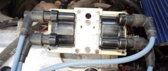
Diagram of the assembled ignition module
Fully assembled ignition module
Video about repairing the ignition module on a VAZ-2112
The video will tell you about repairing the ignition module and how to remove it from the car.