02/28/2022 44 396 Ignition system
Author: Ivan Baranov
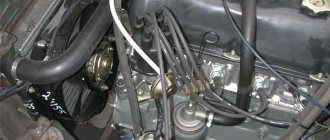
The ZMZ 402 engine is one of the products of the Russian automotive industry, widely used in the automotive industry. These power units were equipped with certain models of Volga, UAZ, and Gazelle cars. To ensure normal engine operation, the machine must have the ignition set correctly. In this article we will tell you how to install a distributor on a 402 engine and what should be taken into account when performing the task.
[Hide]
Setting the ignition timing of GAZ-2705 with engine 402
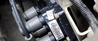
The ZMZ0-402 type engine is equipped with an ignition distributor sensor (1908.3706) - non-contact, with a control pulse sensor (generator) and built-in vacuum and centrifugal ignition timing regulators.
The distribution sensor performs two functions: it sets the moment of sparking and distributes high voltage pulses among the cylinders in accordance with the order of their operation.
For this purpose, a slider mounted on the shaft of the sensor-distributor is used.
An interference suppression resistor* is installed in the slider.
The switch (1313734) opens the power supply circuit of the primary winding of the ignition coil, converting the sensor control pulses into current pulses in the ignition coil.
Injection motor
In terms of technical characteristics and components, an engine with an injection power system is not very different from the carburetor analogue of the 405 model.
With proper operation, this unit is no less reliable and practical than with a carburetor, and in addition has its own advantages:
- Stable idle speed.
- Low level of harmful emissions into the atmosphere.
- The efficiency of the ZMZ-406 injector is much higher than its analogue with a carburetor, since the fuel mixture is supplied in a timely manner and in the right quantity. Accordingly, fuel savings are obvious.
- Improved fuel economy.
- Does not require prolonged engine warm-up in winter.
Adjusting the ignition timing
We install the crankshaft in a position corresponding to the ignition timing angle of 5°.
1. To do this, on the ZMZ-402 engine, we combine the middle mark on its pulley with the tide on the block cover (the end of the compression stroke of the first cylinder).
2. For the UMZ-4215 engine, place the first mark on the pulley against the pin on the timing gear cover.
3. If the distributor sensor is not removed from the engine, then the compression stroke of the first cylinder is determined by removing the distributor cap; the slider should be against the internal contact of the cover, connected by a wire to the spark plug of the first cylinder.
Otherwise, turn out the spark plug of the first cylinder. Closing the hole with a paper stopper, rotate the crankshaft.
The air pushing out the plug will indicate the beginning of the compression stroke.
4. Using a “10” wrench, loosen the octane corrector screw
5. Set its scale to zero division (middle of the scale).
6. Using a “10” wrench, loosen the screw securing the octane corrector plate
7. Rotating the housing of the sensor-distributor, we align the “marks” (red mark on the rotor and arrow on the stator). Holding the sensor in this position, tighten the screw.
Make sure that the slider is located against the contact of the cover of the first cylinder and check that the high-voltage wires of the remaining cylinders are connected correctly - counting counterclockwise from the first cylinder in the order 1-2-4-3.
After you have done everything, check that the ignition timing is set correctly while the car is moving.
We start the engine, warm it up, and when we have already switched to fourth gear at a speed of 50 - 60 km/h, sharply press the gas. If in this case detonation (the sound is similar to the knocking of valves) appears briefly - for 1-3 s - the ignition timing has been chosen correctly.
Prolonged detonation indicates an excessive ignition timing; use an octane corrector to reduce it by one notch.
The absence of detonation requires an increase in the ignition timing, after which the test must be repeated.
A more accurate setting of the ignition timing can be checked using a strobe light in accordance with the instructions included with the strobe light.
Technical characteristics of the ignition system
Cylinder operating order
Direction of rotation of the distributor rotor
counterclock-wise
Ignition timing max, degrees:
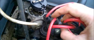
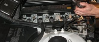
Removing the distributor assembly with the oil pump drive
Remove the distributor cover with tips and high-voltage wires.
In this position, we remember or mark the position of the slider relative to the body.
Disconnect the switch wire from the distributor
Disconnect the vacuum regulator hose.
Using a 13mm wrench, unscrew the two fastening nuts
Remove the distributor sensor assembly with the oil pump drive from the engine.
A gasket is installed under the drive.
If the position of the crankshaft remains unchanged, install the distributor sensor (slider opposite the mark) in the reverse order, after which we adjust the ignition timing (see article - Adjusting the ignition timing of the ZMZ-402 engine).
If the position of the crankshaft has changed, install the distributor sensor in the following sequence: move the piston of the first cylinder to TDC, aligning the corresponding pulley mark with the indicator protrusion on the cylinder block.
In this case, both valves of the first cylinder are closed (see the article - “Adjusting the valve clearances of the ZMZ-402 engine”).
Mark on the ZMZ-402 engine (Fig.
Mark on the UMZ-4215 engine (Fig. 9)
Using a 10mm wrench, unscrew the octane corrector screw and disconnect the distributor sensor from the drive (Fig. 10).
By turning the drive shaft by 45° (the position is shown in Fig. 11), we install the drive into the cylinder block.
The roller will return to its original position, its slot will become parallel to the longitudinal axis of the engine and will be shifted outward relative to the center of the roller (Fig. 12).
We install the distributor sensor and adjust the ignition (see the article - “Adjusting the ignition timing of the ZMZ-402 engine”).
What is the connection diagram for electronic or contactless ignition on a UAZ 417, how to convert contact ignition to contactless? Why does the coil heat up and how to adjust and adjust the advance angle? First, let’s look at the main points regarding the action and types of SZ.
Operating principle of SZ
The ignition system, or rather its correct setting, plays a big role in the operation and starting of a car engine. With correct adjustment, the combustible mixture will burn correctly in the power unit as a result of the supply of charge through the spark plugs. A spark plug is placed on each cylinder of the UAZ engine, each of which is turned on in a certain order, in turn, delivering a discharge to the cylinder after a certain time. It must be taken into account that any SZ makes it possible not only to deliver the required discharge, but also determines its strength.
Due to its technical characteristics, the car’s battery cannot produce the voltage and current required to ignite the mixture. This is due to the fact that the battery can only produce a current of a certain strength. And thanks to the correct operation of the system, the current value increases significantly, which allows you to successfully ignite the air-fuel mixture.
The operating principle of the system consists of several stages:
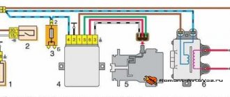
Diagram of the UAZ contactless system
Domestic UAZ vehicles can use one of three ignition systems; let’s look at each of them in detail:
Read more: New BMW M4 2016-2017 price characteristics photo tuning and video test drive of the model So, how to set the advance angle yourself in order to achieve proper operation of the UAZ engine:
Before installing a new distributor with a drive, you need to weigh your strengths, since it is not recommended to make mistakes when performing work.
So, how to replace and install the distributor:
GAZ Club community
It’s almost worth using a strobe light on the VOLGA. The MH is installed at the middle mark (for the 92nd, or in the center between 3 and 2 for the 80th). If there is a BSZ, you need to combine the mark on the magnet with the arrow on the sensor coil body (at the same time, turn the magnet to the right until it stops). Before installing the MZ, set the middle mark of the octane corrector opposite the arrow of the washer under the fastening bolt, make the adjustment itself by releasing the bolt from the BOTTOM REAR of the pump body (if there is not enough adjustment space with the bottom bolt, use the octane corrector bolt). The final adjustment of the OZ should be carried out on the road (from a speed of 40 km/h, sharply press the gas to the floor. A short-term DETONATION should appear. The knocking can occur up to 65-70 km/h). Fortune.
Dude who helps from time to time Messages: 532 Registered: 05 Sep 2013, 16:54 From: Ryazan Contact information:
There is a factory annotation that is unclear.
This is a table for the 402nd motor.
1. Turn off the vacuum pump using a straw.
2. Specifically check -
600 rpm - 5 g advance, this is the middle or second mark on the crankshaft pulley. We look with a strobe light. 1st mark - TDC, 3rd - 12 deg.
Then we put the assistant in the cab, he uses the gas pedal to increase the speed to approximately 850. Looking at the table, it should be 10 g. Using a stroboscope, look at the marks somewhere between the 2nd and third marks of the crankshaft pulley.
Then the assistant increases the engine speed to approximately 1250. The stroboscope should show 12-14 degrees, i.e. 3rd mark on the c/v pulley.
Further 1750 rpm = 15-18 degrees, from the third mark you need to add a distance with a marker equal to the length between the first and 2nd marks, i.e. 125=17 g advance.
In fact, there is another method, I'll look for it at the moment.
Last edited by Dude on Sep 14, 2013, 01:26 pm, edited 1 time in total.
Dude who helps from time to time Messages: 532 Registered: 05 Sep 2013, 16:54 From: Ryazan Contact information:
It was like this: it jerks at 1500 rpm. on any transmission. And what’s most interesting is that it’s on gas. that on gasoline. What I did in the fight for stability: I replaced the spark plugs. I changed the wires, the trampler, the crosspieces, the rims and the wheels, but the problem was as it was
This is an incorrectly installed ignition and an unconfigured distributor. 99.9%.
It is easy to check - the distributor is 1-2 divisions in the later direction - counterclockwise. And at 1500 rpm we check whether the twitching is gone or not. How it drives in the rest of the spectrum is not yet interesting, so far only 1500 rpm.
If this is a problem, we begin to configure the distributor.
We turn on the second speed, try to move off at idle with 2nd or with a small throttle boost. We remember how the car started moving, sorry, here we can only measure it with a pomeranian, I don’t know the best method. Next, we first turn the trailer by 1 division clockwise, then counterclockwise. The point of all these actions is to find the position of the distributor for the best start at XX or min rpm, the best torque, and light pressure on the accelerator.
Next we set up a small distributor spring. This will be a spectrum from approximately idle to 1500 rpm. Everything is the same as we set up XX. Distributor one division clockwise, check, one division counterclockwise, check. Determines the best position of the brake for accelerating the XX-1500. If the positions of the distributor for the spectrum of a small spring and the spectrum of XX coincide, then great; if they do not coincide, then we bend or weaken the stand of the small spring in the distributor. There is a special window in the distributor for this. Just figure out in which case where to bend it. And similarly we adjust the huge spring of the distributor for the best acceleration and the highest traction and low pressure on the gas pedal. A large spring comes into operation here and there after 1500-2000 rpm.
Crankshaft
Cast from cast iron with subsequent processing and hardening of the surface of the journals with high frequency currents. It is installed in the block on five main bearings.
The movement of the crankshaft according to the axis is limited by corkscrew half-rings, which are located in the flow grooves of the support and the cover of the third main bearing. There are eight counterweights on the shaft. A flywheel is attached to the rear of the shaft, in the hole of which a spacer sleeve and a rolling bearing of the gearbox input shaft are pressed.
Adjusting and installing the ignition ZMZ 402: secrets and tips
The ZMZ 402 engine is one of the products of the Russian automotive industry, widely used in the automotive industry. These power units were equipped with certain models of Volga, UAZ, and Gazelle cars. To ensure normal engine operation, the machine must have the ignition set correctly. In this article we will tell you how to install a distributor on a 402 engine and what should be taken into account when performing the task.
Checking for correct installation
If the order is followed without errors in the ignition of the 402 engine, then the next task will be to check the power plant while the car is moving:
- We go out onto the highway and, when driving 60 km/h, turn on fourth gear. We are accelerating. The appearance of short-term detonation knocks indicates that the ignition is installed correctly.
- Prolonged detonation knocks are confirmation of incorrect setting of the advance angle.
In this case, you should reduce it with an octane corrector, moving it to one notch. If detonation cannot be heard at all, then the advanced ignition angle of the fuel mixture should be increased. And check again for correct installation by accelerating the car to 60 km/h and shifting to fourth gear.
What you need to know
In order to properly configure and adjust the ignition of the ZMZ 402, you need to know some nuances about the operation of the power unit. Such motors have a non-contact distributor installed, supplemented by a control signal generator and mounted advance regulators - vacuum and centrifugal (video author - smotri Vidik).
The distributor is designed to perform certain functions:
- determines the moment of spark occurrence;
- transmits high voltage signals through the cylinders of the power unit, taking into account the order of their operation.
For the correct distribution of impulses, a slider mounted on the mechanism pulley is used. The slider is equipped with a resistor and is designed to suppress interference. The switching device performs the function of opening the ignition coil winding circuit, converting control signals from the regulator into short-circuit current signals.
To correctly install the ignition on a 402 engine, it is necessary to take into account the system characteristics presented below:
- the order of operation of the cylinders is first the first, then the second, then the fourth and third;
- the rotor of the distribution element rotates counterclockwise;
- on a centrifugal device the advance angle is from 15 to 18 degrees;
- on a vacuum device this indicator is from 8 to 10 degrees;
- the play on the NW should be no more than 0.8 mm;
- the resistor resistance value should be from 5 to 8 kOhm;
- the SZ resistance parameter should vary around 4-7 kOhm;
- in the stator winding the resistance level should be no more than 0.45 and no less than 0.5 kOhm.
Disassembled distributor for ZMZ
Carburetor engine
The ZMZ-406 carburetor (402nd engine) has been produced since 1996 and has managed to establish itself as a simple and reliable unit. This device develops a power of 110 horsepower. The fuel consumption of a car with this engine often depends on driving style and operating conditions. The power system of the carburetor unit is quite reliable. With timely maintenance and normal operation, using high-quality lubricants and gasoline, it can travel up to 500 thousand kilometers without serious breakdowns. Of course, with the exception of boring the crankshaft, which is necessary for this unit once every 250 thousand kilometers.
How to install the ignition yourself?
How is the ignition installed on the ZMZ 402? The crankshaft must be placed in a position that corresponds to an advance angle of 5 degrees.
You need to set the moment like this:
- On the power unit, we combine the average mark on its shaft on the cylinder head cover, that is, at the end of the compression stroke on cylinder 1.
- If the distributor has not been removed from the power unit, the compression stroke on cylinder 1 can be detected by opening its cover. It is necessary that the slider be installed opposite the internal contact, which is connected via a cable to the spark plug. If it is not possible to determine the compression in this way, you can dismantle the SZ installed in the first cylinder. After this, the hole will need to be covered with a rag, or better yet, with paper. The crankshaft needs to start rotating, and at the moment when the paper plug is knocked out by the air flow, the compression stroke begins.
- Now you will need a 10mm wrench - with its help you need to slightly loosen the octane corrector bolt, but you do not need to unscrew the screw itself.
- Next, you should set its scale to zero, this is approximately the middle of the scale.
- After completing these steps, using a 10mm wrench, you need to loosen the bolt that secures the octane corrector plates.
- Now you need to rotate the distributor body so that the marks are aligned. In particular, we are talking about the red mark located on the rotor, as well as the risk on the stator. When the installation of the device drive is completed, the distributor must be held in this position with one hand, and the bolt must be tightened with the other hand.
Pistons
They are cast from aluminum alloy and have grooves for two compression rings and one oil scraper ring. During operation, the piston crown is cooled by oil through an oil nipple in the upper end of the connecting rod.
The spherical working surface of the upper compression ring has a layer of chrome coating, which facilitates better grinding of the ring. The second element is coated with a layer of tin. The oil scraper ring is of a combined type; it consists of an expander and two steel discs. The piston is attached to the connecting rod using a pin fixed to two corkscrew rings.
How the ignition system works
For the ZMZ 402 model, this order looks like this:
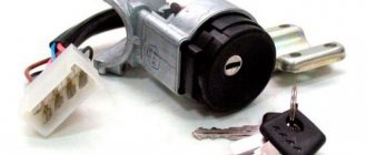
The car engine is started by turning the key in the ignition switch - at this moment the charge from the battery is supplied to the starter, which begins to rotate the crankshaft, activating the distributor (via the drive). At this very moment, electric current is supplied to the coil, then through the commutator the charge is supplied to the spark distributor (distributor), which in turn distributes the current through the wires to the cylinder spark plugs.
IMPORTANT to know that the switch is a block of transistor switches that serves to control the currents that pass through the inductor.
Early ignition
One of the most common problems with the ignition system is too early an ignition timing angle - this is when, when fuel is supplied to the engine cylinder, the working mixture of gasoline and air in the combustion chamber ignites much earlier than the piston approaches top dead center. If the initial ignition timing is set too early, then problems with the vehicle's performance may occur. To avoid this, you should pay attention to signs of early ignition. And this is: • The engine does not start the first time (the crankshaft turns in the opposite direction when starting the engine) • Unstable operation of the engine at idle • Detonation of unburned fuel (a chirping sound appears that does not disappear when the speed increases) • Carbon deposits on the spark plugs ignition (fuel that is not completely burned is deposited on the spark plug) • Shots in the muffler (fuel burns due to misfire of the ignition) • Black smoke from the muffler (fuel that is not burned in the combustion chamber burns out) • Increased fuel consumption
Late ignition
On engines with a carburetor power supply system, late ignition is the ignition of the fuel mixture at the moment when the piston has already reached top dead center or has already passed it. When the engine operates this way, fuel consumption increases, power and throttle response deteriorate. The main signs of late ignition are: • Trouble starting the engine (several attempts are needed) • Sluggish vehicle dynamics while driving (the engine stalls when the speed increases) • Spark plugs are light gray or white • Shots in the carburetor (fuel burns out in the intake manifold) ) • Engine overheating (the mixture burns out during the expansion stroke, which contributes to engine overheating)
Malfunctions and their elimination
Like any technical product, the Gazelle-Business motor is susceptible to breakdowns. Sometimes it needs repairs for various reasons. The most common problems that arise are:
- The motor does not start. Most likely there is no fuel supply to the injectors. It is necessary to use the appropriate fuel, rinse and clean the fuel intake.
- The tightness of the pipeline between the tank and the electric pump is broken. The connection points should be checked and the tightness restored.
- There are problems with the control electronics. It is necessary to replace faulty parts of the unit.
- Poor power delivery indicates problems in the electronic control system. After testing, it is necessary to replace the unusable element.
- The fine filter is clogged. In this case, the filter element must be replaced.
- Air appears in the fuel block. It is necessary to check and ensure the tightness of the system.
- If problems are detected in the fuel pump, the faulty injectors should be replaced.
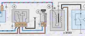
Procedure for adjusting the ignition system
To correctly install the ignition on the ZMZ 402 engine, the following factors must be taken into account: • The engine operating order is 1-2-4-3 • The distributor rotor rotates counterclockwise • The backlash on the spark plug should be no more than 0.8 mm • The resistance value of the resistor on the distributor should be from 5 to 8 kOhm • The resistance value on the spark plug ranges from 4 to 7 kOhm • The stator winding resistance varies from 0.45 kOhm to 0.5 kOhm
Label matching
To begin setting the correct ignition timing, you need to turn the crankshaft to a position that indicates 5 degrees. This is done as follows - you need to set the first cylinder at top dead center (end of the compression stroke). To do this, you need to align the middle mark on the crankshaft pulley with the mark on the cylinder head.
ATTENTION. The compression stroke on the first cylinder can be set if the distributor has not been removed before - by opening its cover, the slider will stand opposite the internal contact of the wire connecting to the spark plugs of the first cylinder.
If it is not possible to determine the compression stroke in this way, then it is necessary to unscrew the spark plug from the first cylinder and plug the hole with a rag or paper. Then you should start cranking the crankshaft until the paper-shaped plug is removed with the help of air created inside the cylinder. This will be the moment of compression.
Advance angle adjustment
Next, you need to loosen the octane corrector bolt, which is located on the distributor. A 10mm wrench will come in handy here. Then the advance angle is set approximately in the middle of the scale (this will be zero). Next, using the same 10mm wrench, you need to loosen the bolt securing the octane corrector plates. The next step is to rotate the distributor housing so that both marks coincide - the red mark on the rotor head and the mark on the stator. When the housing is installed in the desired position, it is necessary to fix the distributor housing with one hand and tighten the bolt with the other.
Preparatory process
Before you begin adjustment work with your own hands, you need to prepare the necessary tools and consumables, which include:
- set of measurement probes;
- a set of wrenches (socket or ring);
- new valve cover gasket;
- crankshaft ratchet key;
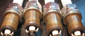
- spark plug wrench Needed to remove spark plugs;
- Phillips and flathead screwdrivers;
- clean rags.
Upon completion of preparation, when all the required tools are prepared, you can proceed directly to the adjustment work.
Starter
With the help of a starter, the engine starts, and how well it works determines whether the car will drive or not. For 3110 motors, starters are produced by many manufacturers, and they also vary in power.
This is what a starter for a Volga 3110 car looks like
For ZMZ 402, there are many types of engine starting devices in terms of power, but they are mainly divided into large and small. A small starter has an average power of about 1 kW, a large one - from 1.5 to 1.8 kW. There are also quite a lot of different manufacturers. The most famous are starters of the brands BATE (Republic of Belarus), KATEK, LKD, FENOX, PRAMO, ZMZ KENO.
Technical characteristics of the Volga
The engine is an in-line four, an eight-valve mechanism. Many parts of the gas 24 engine were made of aluminum-zinc alloy: the internal combustion engine block, the cylinder head, the intake manifold. The body was produced in two versions - sedan and station wagon.
The volume of the fuel tank was 55 liters, since the consumption was relatively large, the tank had to be not small. It was located under the bottom of the trunk. Another feature of the tank was two sensors for measuring the amount of fuel. Manually, by placing the car on a flat surface, you could unscrew the plate with divisions from the tank, which showed the remaining fuel on the instrument panel.
The latter often failed and car owners often used a manual one. Fuel consumption ranged from 10-13 liters per 100 km. Transmission - 4-speed with synchronizers for all gears, single disc clutch, dry with hydraulic drive. Chassis: front independent, multi-link, pivot type. Rear: dependent, spring. Shock absorbers are telescopic, double-sided. Braking system: drum, installed on all 4 wheels. Parking brake with rear wheel drive.
Source
Instructions for connecting short circuit
The ZMZ 405, 406 and 409 engines use two short circuits - one of them works with cylinders 1 and 4, and the second with cylinders 2 and 3. The first of them is located closer to the intake manifold, and the second is located next to the exhaust manifold. To make the connection correctly, low voltage wires should be connected in pairs - those used for the first coil (cylinders 1-4) will be shorter in length. Since the short circuits themselves are not polar, it does not matter which contact the cable will be connected to; it also does not play a role within the pair to which cylinder the wire will be connected (the author of the video is the SpawnyXC90 channel).
Brief history of the car
The Volga was the dream of every Soviet family, but the average resident could not afford it. This car became the next generation of the GAZ-21 brand. Many developments and prototypes were made from 1960 to 1967.
Many engine options were considered, including a V-8 engine for gas 24, but in the end, only two options remained: an in-line four-cylinder with V = 2.5 liters and a 4-speed manual transmission and a 5.5 with a 3-automatic transmission. The body design was based on the American school and the car became similar to its American counterparts, such as: Plimutee Volare, Dodge Dart, Chevrolet Nova.
This is what the gearbox looks like for Volga GAZ 24
Over time, this model became widespread in taxi companies, medical institutions, police, and the famous “Black Volga” was used by officials and law enforcement services.
Oil
The ZMZ-406 power plant is equipped with a combined lubrication system. Under the influence of pressure, the process of lubrication of the piston pins, connecting rod and main bearings of the crankshaft occurs, the support points of the camshafts, the hydraulic valve drive, the intermediate shaft and the driven gear of the oil pump are lubricated. All other parts and elements of the motor are lubricated by spraying oil.
Closed crankcase ventilation with forced exhaust of gases.