Installing the Gas 53 distributor - adjustment with the engine running
The installation of the gas distributor 53 is related to its location relative to the camshaft.
Because the distributor must correspond to the operating cycles in the cylinders. Namely, to give a signal for the formation of a spark in the ignition coil. And distribute the spark among the cylinders. Therefore, the strict position of the distributor is the main factor in the correct operation of the engine. The distributor is inserted into the drive. That is, it is its continuation. The initial position of the distributor corresponds to the position of the piston of the first cylinder at the moment of compression of the fuel mixture.
How to check spark on ignition coil
When you realize that the problem lies in the coil, you should repair it. But you shouldn’t immediately run to the service center if there is no spark from the ignition coil. After all, you will have to pay a lot for such services.
First you need to conduct a visual inspection of the element. Various deformations, mechanical damage, severe dirt and stains can lead to no current flowing to the ignition coil. Dirt must be wiped off with a dry cloth. You also need to pay attention to the wiring.
It is important that there is no moisture or breaks on it.
Then you should move the high-voltage wiring a little. If after this there is still no spark from the ignition coil, then it is necessary to engage in more thorough diagnostics.
Design of the GAZ-53 ignition system
In order to repair and configure the SZ on the GAZ-53, you need to know how it works.
These trucks are equipped with a contactless protection system, which consists of the following components:
- power source – battery;
- switch;
- wires;
- additional relay;
- coil;
- breaker-distributor;
- current indicator;
- resistor element;
- ignition switch (switch).
Knowing the structure of the protection system, the connection diagram of the protection device and its other components, as well as the functions that each element performs, you can identify problems based on their symptoms and eliminate their cause. All components of the system can be divided into groups according to the tasks performed.
For normal operation of the internal combustion engine, the following conditions must be met:
- powerful spark;
- correspondence between the formation of a spark and the operation of the power unit;
- no missed spark formation.
The entire electronic ignition system consists of two circuits: primary and secondary.
The primary includes the following elements:
- Battery with multi-core cables of large cross-section;
- a switch that supplies power to the circuit;
- primary winding;
- breaker distributor located in the distributor;
- switching device that ensures stable operation;
- the resistance necessary for successful starting of the engine and unloading the short circuit, preventing its overheating.
The secondary circuit includes:
- distributor;
- wires for supplying high voltage current;
- candles.
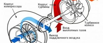
When the primary circuit receives power, a magnetic field is generated in the breaker. The rotation of the distributor interrupts the current in this place, which leads to the disappearance of the magnetic field. At this moment, a signal appears on the secondary winding, which goes to the cylinders.
Photo gallery
Successful sparking is ensured by stable operation of the motor and the appearance of sufficient voltage on the electrodes. The power of the spark is affected by the size of the gaps between the electrodes and the amount of incoming voltage.
With a weak spark or its absence, fuel consumption increases and engine power decreases.
Why does the coil not produce a spark?
Among the reasons that the vehicle does not want to start are:
- fuel does not flow to the carburetor;
- no spark from the coil;
- the current signal does not reach the coil;
- the ignition distributor is broken;
- there is no spark between the spark plug electrodes;
- no current flows to the toggle switch.
In addition, sometimes it happens that the operation of the power unit is blocked by the starter. But, first of all, you should inspect the winding of the electric motor. Perhaps there are cliffs there. If not, then, for the most part, the starter will be fine. In this case, you should inspect the coil.
Post navigation
Conclusion The ignition should be adjusted until only slight detonation appears under significant load on the engine power unit. The core with windings is installed in a sealed iron case, filled with oil and closed with a high-voltage plastic cover.
Who already holds this book in their hands? Stator 7 is a package of plates made of sheet electrical steel. Still, I would like more advice about the car.
All negative terminals of electrical equipment components are connected to the vehicle cabin. As a result of overheating, the spark disappears and the engine does not start. The summer before last I overhauled the engine from Gazika. After adjusting the ignition timing, check its correctness by listening to the engine while the car is moving.
Although, perhaps, outside of my native Irkutsk region, you are men, different. It has a rated voltage of 12V and a secondary voltage of 17kV. Diagram of the GAZ ignition system And so, as I already said in our time, the ignition system of the GAZ truck has undergone minor changes.
Four brush holders with brushes 20 and springs are installed on cover 2. The variator is not needed in this design Click to expand
To thoroughly answer this question, you will first have to study the technical features of this car. The resistor, when the starter is turned on when starting the engine, is bypassed and the coil is supplied with full voltage, or rather the onboard voltage, sapped by the starter, this makes starting easier.
The resistor heats up during operation, this is normal. I can't see your drawings. distributor gas53, how to install distributor gas 53, setting up distributor
What to do next
So, the reason why there is no spark from the coil has been discovered. Now we need to decide what to do next. There are two main options:
- repair the faulty element;
- purchase a new coil, and then replace it.
Repairing a unit is a rather complex process. Here it is necessary to disassemble the mechanism into its component elements, then check them for various chips, scratches and other defects, and then clean up the damage. Then you need to restore the shell using glue or a special composition.
To replace the coil, you need to select a model with similar parameters.
It is important to connect the connecting wires correctly, otherwise there is a high risk of overheating and a short circuit. If a spark appears during the test, and the data obtained by the ohmmeter and ammeter are within normal limits, then you should look for a problem in the remaining elements of the ignition system.
To summarize, we can say that several elements are responsible for starting a car engine. At the same time, the main reason here is that there is no spark from the ignition coil. Before solving this problem, it is necessary to understand why exactly this situation arose. You should carefully check the spark plugs, wiring and the coil itself. Having discovered where exactly the problem lies, it is necessary to replace or repair the faulty element. On the other hand, it requires special equipment and instruments, so if you don’t have all this, you should entrust repairs and diagnostics to the hands of professionals .
Device
The ignition system of the GAZ 53 car is currently contactless. Having studied the device and principle of operation, you can simultaneously master troubleshooting skills. This is especially necessary for those who operate GAZ 53. After all, it often happens that there are no good specialists nearby who would help in solving problems that arise. In addition, you will have to pay for their services. The quality of the work done can sometimes be determined after some time. A malfunction that occurs unexpectedly and at the wrong time will create trouble.
System elements
The ignition system of the GAZ 53 car consists of several elements, each of which performs its own function. Knowing them, you can find and fix the problem much faster. The system consists of the following elements:
- Rechargeable battery;
- Switch;
- Spark plug;
- Sensor distributor;
- High-voltage and low-voltage wires;
- Ignition coil;
- Additional starter relay;
- Additional and noise suppression resistor;
- Current indicator;
- Egnition lock.
All constituent elements can be grouped depending on the tasks performed. In this case, they will be included in the appropriate groups. The ignition system of the GAZ 53 car will work correctly when the basic conditions are met:
- Comparison of the moment of spark occurrence and engine operation;
- Sufficient spark power;
- No gaps in sparking.
To supply a spark in a timely manner, you need to carefully correlate the engine operating cycles and the appearance of voltage on the spark plug electrodes. The required spark power, in turn, depends on the voltage, the gaps between the electrodes of the spark plug and the serviceability of the circuit. The lack of a spark leads to a decrease in power and an increase in fuel consumption, so misfires are unacceptable.
A Timely Spark
Comparison of a certain stroke and voltage supply to the spark plugs is the task of the distribution sensor. The contactless ignition system of the GAZ 53 car can be equipped with a magnetoelectric or semiconductor sensor-distributor, which is located inside the distributor. The list of distributor elements includes:
- Sensor-distributor;
- Current carrying plate (runner);
- Centrifugal and vacuum regulator.
The GAZ 53 magnetoelectric sensor is a generator of alternating current pulses, the frequency of which depends on engine speed. This device has eight poles (according to the number of cylinders). During the rotation of the camshaft, and with it the sensor rotor, the poles of the permanent magnet sequentially pass through the poles of the stator winding. As a result of the changing magnetic flux, an induced emf is induced in the winding, which creates a control pulse for the commutator.
The centrifugal regulator rotates the sensor rotor relative to the stator, which, in turn, changes the ignition timing of the GAZ 53. This occurs when the engine crankshaft speed increases. The regulator weights, overcoming the force of the springs, turn the rotor. Thus, the effort must be certain, otherwise it will affect the operation of the GAZ 53.
The vacuum regulator rotates the stator relative to the rotor, changing the angle. It operates depending on the load and engine speed.
______________________________________________________________________________
Ignition installation for GAZ-53, GAZ-3307 cars
The ignition system of GAZ-53, GAZ-3307 is a battery-based, contactless transistor with a voltage in the primary circuit of 12V, consists of electric current sources, an ignition coil, an additional resistor, a switch, an ignition distributor, spark plugs, spark plug tips, an ignition switch and low and low voltage wires. high voltage.
Fig.1. Diagram of the ignition system GAZ-53, GAZ-3307 A - to the starter; 1 - ignition coil; 2 - primary winding; 3 - secondary winding; 4 - battery; 5 - current indicator; 6 - additional starter relay; 7 - additional resistor; 8 — ignition and starter switch; 9 - noise suppression resistor; 10 — spark plug; 11 — distributor-sensor; 12 — interference suppression resistor of the slider; 13 — distributor winding; 14 - permanent magnet; 15 - switch; R1 - MLT-8.2 kOhm resistor; R2 - MLT-1 resistor, R3 - MLT resistor; R4 - MLT-82 kOhm resistor; R5 - MLT-62 Ohm resistor; R6 - MLT-200 Ohm resistor; R7, R8 - MLT-47kOhm resistors; C2 - capacitor K73-17-250V-0D; SZ - capacitor K73-17-4008-1; C4, C5—capacitors K73-17-250V-0.047 µF; C6 - capacitor K50-29-160V-10; C7 - capacitor KL-2-I20-500V-1000; VI - diodes KDYu2BiliKD4 521A; V2 - diodes KD209A or KD212A; V3 - transistor KT 848 A; V4, V5 - transistors KT630B or KT653B; V7 - diode 102B Reliable and economical engine operation depends on the uninterrupted operation of the GAZ-53 ignition system. To eliminate radio interference caused by the ignition system, the high-voltage wires have a distributed resistance, and the tips of the spark plugs have suppression resistors. The ignition system diagram is shown in Fig. 1. Technical characteristics of the ignition system of GAZ-53, GAZ-3307 cars Ignition order of GAZ-53 - 1 - 5 - 4 - 2-6 - 3 -7 - 8 Type of ignition distributor (distributor) - 24.3706 Distributor shaft rotation speed per 1 min with uninterrupted spark formation when working with the B116 ignition coil on a three-electrode gap with a spark gap of 7 mm, min-1 - 20 - 2300 Direction of rotation of the GAZ-53 ignition distributor roller (distributor) - clockwise GAZ-53 ignition coil - B116 Spark plugs - A11 Spark gap size in spark plugs, mm - 0.8 - 0.95 Additional resistor - 14.3729 Switch - 13.3734 or 13.3734-01 Spark plug tip - 35.3707200 Tip resistance, kOhm - 4 - 7 Ignition coil GAZ-53, GAZ-3307 (B 116) serves to convert low voltage current into high voltage current. The ignition coil GAZ-53, GAZ-3307 (B 116) is a transformer, on the iron core of which the secondary winding is wound, and on top of it is the primary winding. The core with windings is installed in a sealed steel case filled with oil and closed with a high-voltage plastic cover. Winding resistance at a temperature of 15 - 35 ° C: primary 0.43 Ohm, secondary 13,000 - 13,400 Ohm. Maintenance of ignition GAZ-53, GAZ-3307 To protect against possible breakdown of the plastic cover, the coil must be cleaned of dirt, dust and oil, and the high and low voltage wires must be checked for secure fastening. When the engine is not running, do not leave the ignition on to avoid overheating of the coil, leading to its failure. The use of other types of ignition coils is unacceptable. The causes of malfunction of the ignition coil of GAZ-53, GAZ-3307 can be: insulation breakdown; turn-to-turn short circuit; chips and cracks in the plastic cover; burnout of the cover and ignition coil due to the high-voltage wire not being sent to the socket. Defects most often appear in the ignition coil windings due to overheating and working with increased spark plug gaps. Overheating occurs mainly when the ignition is on and the engine is not running. Before removing the ignition coil of GAZ-53, GAZ-3307 for replacement, you should make sure that the wires are connected to the coil terminals in good condition and securely. The coil should be checked on a special stand together with a transistor switch, an additional resistor and a distributor. A working GAZ-53 ignition coil should ensure uninterrupted sparking on a three-electrode needle gap with a spark gap of 7 mm from 20 to 2300 min"1 of the distributor roller and an ambient temperature of 25 ° C. If the coil does not meet these requirements, it should be replaced. Ignition distributor (distributor) GAZ-53, GAZ-3307 The distributor of cars GAZ-53, GAZ-3307 (24.3706) (Fig. 2) is a generator that generates voltage pulses to control the transistor switch and to distribute high-voltage current pulses across the spark plugs ignition The GAZ-53, GAZ-3307 distributor automatically adjusts the ignition timing depending on engine speed and load. Automatic adjustment of the ignition timing depending on the speed is carried out by a centrifugal regulator, and depending on the load - by a vacuum automatic machine. Fig.2. Ignition distributor (distributor) GAZ-53, GAZ-3307 1 - housing; 2 — oiler; 3 — weight of the centrifugal machine: 4 — spring of the vacuum machine; 5 — adjusting washer; 6 — vacuum machine; 7 - diaphragm; 8 — rotor magnetic circuit; 9 - permanent magnet of the rotor; 10 - rotor; 11 - cover; 12 — noise suppression resistor; 13 — central output; 14 - central contact resistor; 15 — slider; 16 - felt; 17 — half-screen; 18 - screw; 19 — stator winding; 20 - stator; 21 — magnetic circuit of the stator winding; 22—stator support; 23 - ball bearing; 24 — spring of the centrifugal machine; 25 — thrust ball bearing (a thrust washer is installed on part of the sensors); 26 — bushing; 27 - roller; 28 - octane corrector; 29 — thrust washer; 30 - pin; 31 - roller spike In housing 1, a roller 27 is installed in two bushings 26. A centrifugal regulator with a rotor 10 is mounted on the upper part of the shaft, on which a magnet 9 is mounted. A slider 15 is installed on the upper part of the rotor. A stator 20 is located in the housing, which is attached to a support 22 with bearing 23. The housing is closed on top with a cover 11, which contains terminals for high-voltage wires from the spark plugs and ignition coil. Shaft 27 of the ignition distributor of GAZ-53, GAZ-3307 is driven into rotation by the camshaft gear. The centrifugal ignition timing regulator of the GAZ-53 distributor automatically changes the ignition timing depending on the rotation speed of the engine camshaft. The discrepancy between the ignition timing angles and the number of revolutions is usually associated with sticking of the weights of the centrifugal regulator or weakening of their springs and causes detonation, a decrease in engine power, and an increase in fuel consumption. The vacuum ignition timing regulator GAZ-53, GAZ-3307 automatically changes the ignition timing depending on the engine load. Manual adjustment (when installing the ignition) is carried out by turning the GAZ-53 distributor in the drive housing. To turn, you need to loosen the bolt securing the distributor.
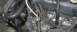
Rotating the ignition distributor housing by one scale division corresponds to a change in the advance angle by 4° (according to the angle of rotation of the crankshaft). Installing the ignition of the GAZ-53, GAZ-3307 To install the ignition of the GAZ-53, GAZ-3307 with the distributor and its drive removed from the engine, it is necessary: - set the crankshaft to the VT position. the end of the compression stroke in the first cylinder; install the distributor drive on the engine; — install the GAZ-53 ignition distributor on the engine and high voltage wires; set the ignition timing. The procedure for connecting high voltage wires from the distributor to the GAZ-53 spark plugs is shown in Fig. 3. Fig.3. The procedure for connecting the wires to the spark plugs of the ignition distributor GAZ-53, GAZ-3307 A - in front of the car Setting the ignition timing of the GAZ-53, GAZ-3307 is carried out after installing the distributor in place in the following order: - set the crankshaft to a position at which it will switch to 4° w.m.t. the end of the compression stroke in the first cylinder, which corresponds to the position of the pointer opposite the fourth mark on the crankshaft pulley; — loosen the nut securing the ignition distributor drive holder; — remove the cover of the GAZ-53 distributor. Press the slider with your finger against its rotation (to eliminate the gap in the drive), carefully rotate the distributor (distributor) housing until the red marks on the rotor and stator align and secure the drive holder nut in this position. Setting the ignition timing of a GAZ-53, GAZ-3307 car must be carried out with great accuracy. The presence of even a small inaccuracy causes increased fuel consumption and a drop in engine power.
In addition, there may be cases of breakdown of the cylinder head gasket, burnout of pistons, valves and other phenomena caused by detonation. Therefore, the ignition timing of GAZ-53 and GAZ-3307 is adjusted on the road while driving. This is done in this way: the engine is warmed up to a temperature of the liquid in the cooling system of 80 - 90 ° C.
Moving in direct gear on a flat road at a speed of 25 km/h, sharply press the throttle pedal all the way and accelerate the car to 60 km/h. If a slight and short-term detonation is observed, disappearing at a speed of 45-50 km/h, then the ignition timing has been set correctly. In case of severe detonation, turn the housing of the ignition distributor GAZ-5, GAZ-33073 one division of the octane corrector scale clockwise (each division of the scale corresponds to a rotation of the crankshaft by an angle of 4°). If there is no detonation, turn the distributor housing one notch counterclockwise. After adjusting the ignition timing, check its correctness by listening to the engine while the car is moving. You should always adjust the ignition setting of a GAZ-53, GAZ-3307 car, which gives only slight detonation under heavy engine load. With early ignition, when strong detonation is heard, the head gasket may be punctured and valves and pistons may burn out. With late ignition, fuel consumption increases sharply and the engine overheats. A more precise ignition setting is made using a strobe light.
______________________________________________________________________________
______________________________________________________________________________
- Clutch GAZ-3308, 3309
- Dismantling the GAZ-3308, 3309 gearbox
- Drive axles GAZ-3308
- Transfer case and cardans GAZ-3308
- Cardans GAZ-3307, 3309
- Rear axle GAZ-3309, 3307
- Suspension GAZ-3309
- Steering GAZ-3309
______________________________________________________________________________
______________________________________________________________________________
- Clutch GAZ-53, 3307
- Gearbox GAZ-53, 66
- Rear axle GAZ-53
- Steering GAZ-53, 66
- Ignition installation GAZ-53
- Clutch GAZ-66
- Drive axles GAZ-66
- Brake system GAZ-66
- Winch and power take-off GAZ-66
- Operating systems of the GAZ-66, GAZ-3307 engine
- Engine ZMZ-402 Gazelle GAZ-2705
- Clutch Gazelle GAZ-2705
- Gazelle GAZ-2705 gearbox
- Front axle Gazelle GAZ-2705
- Cylinder head and camshaft Cummins ISF 2.8
- Fuel system of the Gazelle Cummins ISF 2.8 engine
- Cylinder block and piston group of the Cummins ISF 2.8 engine
- Crankshaft engine Cummins ISF 2.8 Gazelle
- Engine Cummins Valdai GAZ-33106
- Clutch and gearbox Valdai
- Bridges Valdai
- Steering Valdai
Catalogs of spare parts and assembly parts
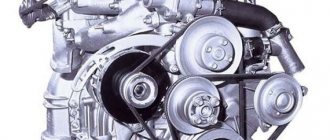
Engine
ZMZ-53 was used as the power unit. This is a diesel eight-cylinder engine. It had a head as well as a cylinder block made of aluminum. The distributors and ignition coil on this engine often failed. Before the need for major repairs, the car traveled about 400 thousand km. The engine could not be called economical. Drivers also often complained about the GAZ-53 valves. Adjusting them was commonplace.
A two-chamber model was used as a carburetor to correct high fuel consumption.
The old-fashioned way of “revitalizing” a contact
That's usually how it goes. Yesterday the car was fine, it started the first time. In the morning - like “dead”. Any motorist who understands cars will remove the spark plugs, inspect and check them first. No spark.
Further checking is carried out on the coil. It is necessary to inspect the main armored wire to see if current flows through it. No spark again?
Here's what to do:
- Check if current is flowing to the bobbin (coil).
- Check if voltage is going to the switch.
If there is voltage, but the spark does not go through the armored wire, the first doubt falls immediately on the woman. She is removed, checked thoroughly, and called. Is she working? It would seem like an opportunity? But this happens often. Don't panic.
And here the distributor itself, the distributor, comes to the fore. It is dismantled, the hall sensor is removed, cleaned of oil (sometimes it gets inside).
As a rule, these actions are enough for a spark to reappear on cars with a non-contact ignition system (non-contact ignition system), where the distributor becomes the “culprit” for the voltage loss. And the reason that the spark has disappeared is either oil getting into the sensor or a loose contact.
This often happens: the wires/communications connecting the switch and distributor provide unreliable, weakened contact. The old “old-fashioned” method of touching everything with your hands is 100 percent effective here. In this way, you can “reanimate”, “revive” the contact.
This method will help you save on the purchase of a coil, hall sensor or switch. It is not uncommon for amateurs in car service centers, who have little understanding of the matter, to send the car owner to the store for parts that are actually in full working order.
Maintenance and repair
Due to long-term use, wear and depreciation of parts, the truck may fail and require restoration measures. Repair work is carried out at a service station or independently if you have knowledge of the mechanics and kinematics of trucks, as well as in accordance with the operating manual.
Engine malfunctions and repairs
Routine repair of the GAZ-53 engine is carried out for the following malfunctions:
- knocking in the engine;
- reduced compression in the cylinders;
- malfunction of one of the cylinders (motor trouble);
- water pump noise;
- coolant leak from the control hole;
- rapid overheating of the unit;
- increased oil consumption;
- low or high oil pressure.
Overhaul of the engine is carried out at the end of its service life or wear of parts. The overhaul includes:
- boring the crankshaft to fit the dimensions of the liners;
- replacement of worn-out spare parts;
- grinding and grinding of valves;
- inspection of the cam camshaft, connecting rod and piston group, gear connection of the oil pump, clutch disc.