A breakdown of the door, in particular its locks, not only causes discomfort for the motorist, but also calls into question the safety of personal belongings, so replacing the VAZ 2114 door lock is not a procedure that should be postponed. Since the quality of production and metal composition of domestic door locks leaves much to be desired, their breakdowns and failures occur quite often.
Trouble can await the driver at any moment when the driver’s door “suddenly” refuses to open and he has to get out through the passenger door. The situation is much worse when, if the lock breaks, the door remains open and the car remains “defenseless”.
Common causes of breakdowns of VAZ 2114 door locks
- The door lock button does not lock and/or the lock cannot be locked with the key. This breakdown is typical when the upper end of the external drive lever is blocked, for example, on the shoulder of the handle.
- It is impossible to open the doors with the outside handle. Occurs as a result of an increase in the flange gap between the outer door handle and the lever in the lock drive.
- The central locking spring or the external drive lever has broken, as a result of which the door does not close.
- When closing the door, the lever tooth does not engage with the ratchet mechanism; this occurs due to the weakening of the rivets on the lever axis.
- The door does not lock because the lock lever is jammed or grease and dust are pressed into the lock.
- The door does not open completely with the inside handle.
The position of the internal door lock lever is out of order, as a result the drive lever does not make full travel. Often, most breakdowns associated with door locks can be fixed with your own hands without having to replace them.
How to connect
Installation of the VAZ-2114 alarm system begins with disconnecting the battery and determining the location of the elements. The control unit is placed under the instrument panel or behind the glove box, the siren is placed in the engine compartment. Guided by the instructions and diagram, all elements are connected.
The control unit is connected through connectors to system elements, components and vehicle parts. Installation and installation begin from the farthest point of installation of the security system element, using 9 connectors (X) for connection.
Sensors (limit switches) are installed in the engine compartment, under the hood and in the trunk, which react to opening. The door trims are dismantled to install activators. The Valet service button is installed in a place hidden from prying eyes, but easily accessible to the car owner.
A transmit-receive antenna is installed on the windshield in the upper corner. It is recommended to install the shock sensor inside the passenger compartment, securing it to a metal surface. The emergency siren is installed in the engine compartment with the bell facing down.
When all the elements are located in their places, you can begin to connect them into a single system.
Scheme
The characteristics of the Starline A 91 car alarm and the connection diagram of the main elements are given in the manufacturer's instructions. When connecting a 6-pin connector X 2, you may need an additional door opener activator.
When connecting door opening sensors, use the blue/red wire of connector X 3. All alarm connection points, i.e. connectors (X) look like this:
- X 9 - connect a two-level shock sensor installed on a metal surface.
- X 8 and X 7 - connectors are not used.
- X 6 - Valet service button, installed in a hidden and easily accessible place.
- X 5 - LED indicator, installed on the instrument panel.
- X 4 - transmitting sensor receiving module; it is recommended to install it in one of the upper corners of the windshield.
- X 3 - connector with many wires.
They are connected to the systems with wires of the following colors:
- Red - with the “plus” of the ignition switch.
- Green/yellow and green/black - sidelights and side turns.
- Black—vehicle mass.
- Yellow - ignition switch (connection to blue/black).
- Gray is the “plus” of the emergency siren.
- Blue/red - “plus” of the door entrance.
- Black/red - additional blocking relay.
- Orange/gray - hood lift sensor.
- Orange/white - trunk opening sensor.
- Orange/purple - to the brakes (according to the diagram in the instructions).
- X 2 - connect door opening activators;
- X 1 - ignition switch (closed with red wire).
Connecting the central lock
In basic configurations, the control unit (CU) of the central locking (CL) performs the function of locking the door lock. The electrical circuit connection diagram is the same for all central locks, the only difference may be in the control unit, activators and the number of pins for connecting an additional device.
The main elements of the central lock include the control unit, door sensor switches (limit switches) and microswitches that fix the position of the key. All these elements are connected to the alarm and interior lighting of the car.
To connect to the central locking, it is necessary to connect the central locking control unit (CU) to the car alarm using the door opening and closing relay, to the car ignition switch and to the door opening sensors. When installing the central locking, you will need additional parts, such as:
- diode 1A - 3 pcs.;
- 3A diode - 1 pc.;
- diode 5A - 2 pcs.
Tapping into wires
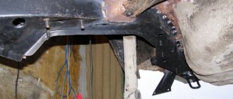
In order to insert into the wires, you first need to free them from under the threshold trim. To do this, unscrew the fastening screws and remove the upholstery. Underneath there are 2 wire harnesses running to the instrument panel. One of the harnesses contains the parking brake wire. 2 wires are connected to the sidelights and side indicators.
When inserting into the parking brake wire, 1 diode is installed, and 2 diodes are installed in the wire that powers the side headlights and side turn indicators. The terminals of the insertion wires are connected to connector X 3 of the alarm control unit.
Autostart
One of the functions of the Starlin car alarm system is auto engine start. In order to install with autostart yourself, you need to use the ignition switch wires. The lilac wire is connected to the battery. Blue (ignition switch) is connected to the alarm control unit via connector X 1.
To connect the tachometer sensor, it is connected to a gray/black wire coming from connector X 3. Connect ground from the main unit using the black wire of connector X 3.
Tips for replacing and adjusting the VAZ 2114 door lock
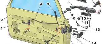
When replacing a door lock, it should be taken into account that there are no fundamental differences in the design of the front and rear door locks. The main difference between the front door locks and the rear ones is that the design provides an additional rod for connecting the cylinders of the door lock switches (cylinders). Accordingly, the door handles are also different, since the front external handles have a hole for the cylinder.
If it is difficult to open the interior door handle, the position of the handle must be adjusted by loosening the fastening screws, and the handle together with the bracket must be moved to the required position.
Door locks of the VAZ 2114 are non-removable and cannot be repaired if they break.
To properly adjust the door locks you must:
- Loosen the door lock bolts.
- It is recommended to outline the contours of the retainer on the body pillar with a simple pencil.
- If the door slams too tightly, it is necessary to move the latch outward. If the door does not close tightly, the latch must be moved inward.
- Accordingly, it is necessary to adjust the latch vertically; if the door goes down, you need to move the latch up, if it rises, then down.
To replace door locks you will need the following tool:
- ratchet and extension;
- "8" head;
- penetrating lubricant WD-40;
- flat and Phillips screwdriver;
- new locks for the door.
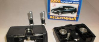
Internal lock for the rear door of VAZ 2109-15: right - 21090620501210, left - 21090620501310, with a price of 200 rubles. Internal lock for the front door of VAZ 2109-15: right - 21080610501210, left - 21080610501310, price 260 rubles.
The cost is indicated for the summer of 2022 in Moscow and the region.
Press the fasteners securing the inner lock handle trim to the door panel and remove the trim.
Using a plastic spatula, remove the armrest handle plug.
Using a Phillips screwdriver, unscrew the two screws securing the armrest handle to the inner door panel.
Remove the armrest handle.
Using a Phillips screwdriver, unscrew the door lock button.
Using a Phillips screwdriver, unscrew the three screws at the bottom of the trim.
Remove the cover.
We take the front shutter glass position switch out of the pocket along with the wiring harness block, and disconnect the wire switch.
Unscrew the four speaker mounting bolts.
We take out the speaker.
Using a spatula or screwdriver, carefully unclip the six pistons and remove the door card.
We disconnect the outer handle rods and the lock switch from the internal lock.
Using a Phillips screwdriver, unscrew the two screws securing the inner door handle. Then remove the inner door lock handle.
Unscrew the two screws securing the door lock.
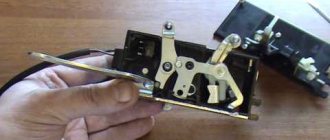
We remove the external and...
... internal door locks.
Remove the locking bracket from the lever pin and disconnect the inner handle rod from the inner lock lever.
We install the lock rods on a new one.
We assemble all the parts in reverse order.
Connection diagram and setup
In the basic instructions, Starline provides a diagram for the A91 model:
Shown here is the harness going to the dashboard. Let's figure out what is connected where:
- The diode connected to the wire break must conduct current in the direction “towards the limit switches”;
- Above we talked about the 1N5401 diode;
- The second diode connected to the alarm wire may be designated 1N4001 (it is cheaper).
Now let's look at what is in the second bundle, located under the first:
From the two blue cables shown above, make T-shaped bends and extend the cords to the alarm installation location. And a 1N4001 diode is installed in the gap in the handbrake wire. The cathode of this diode “looks” towards the switch. Finally you will make the connections:
- The “green-yellow” and “green-black” wires from connector X3 are connected to the turn signal leads.
- Another tap coming from the cathode is connected to the “brake input” of the Starline A91 Dialog signaling system. The cord is designated as “orange-purple”.
It was discussed how to connect all the signal wires with your own hands. Queue for the security forces.
The steps listed in this chapter can be completed before installing the alarm. The functionality of standard equipment should not be affected.
Connecting the autostart connector
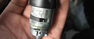
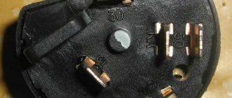
In VAZ 2114 cars, unlike the “nines”, an ignition switch with three terminals is used: 50, 15 and 30. The latter is connected to the battery, and contact 15 closes with it when the key is turned. Well, the 50th terminal is the “output "to the starter. Similar designations are used not only by VAZ.
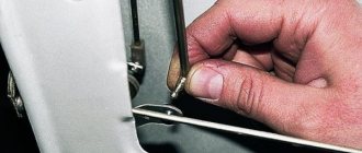
As for model 2114, the lock escutcheon is secured with three self-tapping screws, as well as three metric screws. Unscrew them and you will see the following:
According to the basic instructions, power for the signaling can be taken from pin 30 (a T-tap is needed). And the “yellow” power cable coming out of connector X1 is connected to terminal 15. Further, if autostart is needed, then:
- The connections above must withstand significant current (up to 30 A);
- The “red” wire coming from the ignition switch is broken;
- The Starline A91 Dialog module is reached by bends coming from the break point;
- The thin wire from connector X1 should connect to terminal 50, while the power cord in “black and yellow” insulation will become the output to the starter.
Also, as stated in the installation manual, do not forget to cut the gearbox selector loop. The action makes sense if autorun is used.
Those who have an immobilizer activated in their car will have to install a crawler. You can buy a BP-3 unit from Starline to connect it to the “pink” control cord of the alarm:
All those who do not want to break the wire of the standard reader make a crawler with their own hands:
- The additional loop antenna contains 50 turns of PEL-0.3 wire;
- The internal antenna of the unit must contain the same number of turns of any wire;
- Both antennas are combined into a circuit opened by relay contacts.
The instructions cannot be completed here. The method of connecting the tachometer was not considered.
It is clear that the loop antenna will need to be combined with a standard reading device. And all the antennas included with Starline crawlers do not fit well with VAZ immobilizers.
The wire in “black-gray” insulation coming from connector X3 is connected to the high-voltage input of the tachometer (see figure). Your alarm will not burn out as a result, but will be able to control the speed:
All Starline security systems, as it turns out, are well compatible with any VAZ cars. This applies even more so to the A91 Dialog model. By the way, do not forget to connect the “ground” of the main unit (“black” cord of connector X3).
Software setup
We will configure only the functions responsible for autorun. You can activate the programming mode as follows:
- The security is turned off, the key in the lock is moved to the “0” mark;
- The Valet button connected to the A91 Dialog main unit is pressed 6 times;
- After step “3”, turn on the ignition immediately;
- 6 beeps sound;
- Use the Valet button to select the function number (see below);
- To set the required value, press the corresponding key on the key fob.
The system operates in Dialog mode, so the function number, as well as its value, will be displayed on the key fob. All the options in question are listed in the table:
Information was taken from the installation instructions. Switch the values of the following functions: 12-3, 11-4 and 9-3.
To set the value to “4”, press the third key until the melody appears. Then the button is pressed again. Having chosen the value 4 for function 11, it is better to perform the following check:
- The “yellow” cord coming from block A91 and connected to terminal 15 is temporarily disconnected;
- Start the engine “with the key”;
- The alarm LED should start flashing.
All these tips are given in the standard instructions. True, they advise disconnecting all wires except three.
Connection diagram and setup
In the basic instructions, Starline provides a diagram for the A91 model:
Shown here is the harness going to the dashboard. Let's figure out what is connected where:
- The diode connected to the wire break must conduct current in the direction “towards the limit switches”;
- Above we talked about the 1N5401 diode;
- The second diode connected to the alarm wire may be designated 1N4001 (it is cheaper).
Now let's look at what is in the second bundle, located under the first:
From the two blue cables shown above, make T-shaped bends and extend the cords to the alarm installation location. And a 1N4001 diode is installed in the gap in the handbrake wire. The cathode of this diode “looks” towards the switch. Finally you will make the connections:
- The “green-yellow” and “green-black” wires from connector X3 are connected to the turn signal leads.
- Another tap coming from the cathode is connected to the “brake input” of the Starline A91 Dialog signaling system. The cord is designated as “orange-purple”.
It was discussed how to connect all the signal wires with your own hands. Queue for the security forces.
The steps listed in this chapter can be completed before installing the alarm. The functionality of standard equipment should not be affected.
Connecting the autostart connector
In VAZ 2114 cars, unlike the “nines”, an ignition switch with three terminals is used: 50, 15 and 30. The latter is connected to the battery, and contact 15 closes with it when the key is turned. Well, the 50th terminal is the “output "to the starter. Similar designations are used not only by VAZ.
As for model 2114, the lock escutcheon is secured with three self-tapping screws, as well as three metric screws. Unscrew them and you will see the following:
According to the basic instructions, power for the signaling can be taken from pin 30 (a T-tap is needed). And the “yellow” power cable coming out of connector X1 is connected to terminal 15. Further, if autostart is needed, then:
- The connections above must withstand significant current (up to 30 A);
- The “red” wire coming from the ignition switch is broken;
- The Starline A91 Dialog module is reached by bends coming from the break point;
- The thin wire from connector X1 should connect to terminal 50, while the power cord in “black and yellow” insulation will become the output to the starter.
Also, as stated in the installation manual, do not forget to cut the gearbox selector loop. The action makes sense if autorun is used.
Those who have an immobilizer activated in their car will have to install a crawler. You can buy a BP-3 unit from Starline to connect it to the “pink” control cord of the alarm:
All those who do not want to break the wire of the standard reader make a crawler with their own hands:
- The additional loop antenna contains 50 turns of PEL-0.3 wire;
- The internal antenna of the unit must contain the same number of turns of any wire;
- Both antennas are combined into a circuit opened by relay contacts.
The instructions cannot be completed here. The method of connecting the tachometer was not considered.
It is clear that the loop antenna will need to be combined with a standard reading device. And all the antennas included with Starline crawlers do not fit well with VAZ immobilizers.
The wire in “black-gray” insulation coming from connector X3 is connected to the high-voltage input of the tachometer (see figure). Your alarm will not burn out as a result, but will be able to control the speed:
All Starline security systems, as it turns out, are well compatible with any VAZ cars. This applies even more so to the A91 Dialog model. By the way, do not forget to connect the “ground” of the main unit (“black” cord of connector X3).
Fixing problems
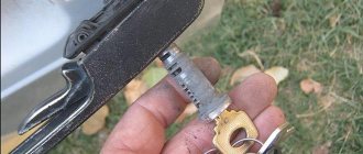
If the key or silumin rod breaks, do not immediately buy a new block with a handle. On sale you can find special repair kits for door handles VAZ 2108-099, where these parts are in 2 copies.
This way, you can save money and change the key yourself without any hassle by removing the handle using this sequence of steps:
- Remove the trim panel.
- Disconnect the handle rod connecting it to the locking device from the mechanism.
- When the glass is fully raised, unscrew the 2 knobs of the handle to the gate card.
- Remove the handle, replace the parts and return them.
If the rod is disabled, the inner pad must be removed and secured in place as described above. The moment the trim panel is removed, make sure it causes that link to come loose so history doesn't repeat itself when the door is closed.
Malfunctions of the locking mechanism can only be eliminated by removing it. In a situation where the device has a lot of wear, as happens on the driver and front passenger doors, it is recommended to replace the lock with a new one.
Once it is in place, adjustments are required to ensure that the locking parts are perfectly aligned. To adjust the locking, you need to lock it in different positions, reaching the optimal value.
Owners of domestically produced cars often need to carry out one or another repair of car parts. One of the common and inconvenient problems is a broken door lock. It forces quick action, as it calls into question the driver’s comfort and the safety of personal belongings.
Do-it-yourself engine start | Motorist's benefit
Probably, many have already heard about remote starting of a car engine; recently we have already published information about how autostart works and how it works. Those who are interested can read this article in more detail. Today we will talk about how to independently make a remote car engine start at home.
Adding the engine auto-start function to a regular alarm system
In this example, we will connect the autostart function to the StarLine A6 car security system. The image shows a schematic diagram of connecting all elements including the remote start module.
The image shows a schematic diagram of connecting all elements including the remote start module.
To connect you will need:
- Universal 4-pin relays – 2 pcs.
- Universal 6-pin relays (22.3777) – 1 pc.
- Schottky diodes SR360 (60A), analogue of diode 1N5822 60A – 3 pcs.
You shouldn’t have any problems assembling the circuit; the only nuance in this story is the low pulse duration of the additional channel on the StarLine A6 alarm (0.6 sec.) or long (10 sec. and 30 sec.), which in one case is not enough to turn on the starter , and in the other there is a lot of this. To solve the problem, it is necessary to reprogram the additional channel for 0.8 seconds, this is enough to start the starter. In the following photos you can see how the assembly and connection were carried out.
The photo shows the connection of diodes to output 85 of the starter relay
We hide the assembled circuit in the torpedo niche
The standard alarm program on channel 3 gives a pulse mode of 0.8 seconds. The first press of the button turns on the ignition, the second turns on the starter, only after 1.5 seconds the engine stalls and the ignition turns off. If the second time you press and hold the button, the engine runs until you release the button, this problem can be solved by reprogramming the alarm to supply a negative contact to certain relay contacts.
Before reprogramming, we have Relay 22.3777 supplies +12 current to the 4th contact when a minus appears and disappears on the 5th contact, and relay 21.3777 supplies a plus to the 4th leg as soon as a minus appears on the 5th.
After programming, relay 22.3777 supplies minus 12 volts to the 4th contact when a minus appears and disappears on the 5th contact, and relay 21.3777 supplies a minus to the 4th leg as soon as a minus appears on the 5th. As a result, we have a remote start with three clicks , and on the fourth, we turn off the engine. The positive aspect of this circuit is the presence of relay 22.3777, which makes a pause for the fuel pump (pause between the 2nd and 3rd press).
How to connect a button?
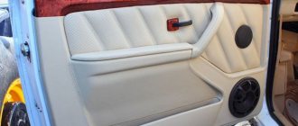
The driver and passenger door buttons are connected to each other, as well as to the ESP motor and power cable. Correct pinout of the power window button:
- Pin 1 on the driver's door is connected to pin 6 on the passenger side. Contact 1 on the passenger door is connected to the negative terminal of the ESP motor.
- Pin 2 on both buttons is connected to power.
- Pin 3 is the ground on the driver's side and the positive wire on the passenger's side.
- Contact 4 in both cases goes to the headlight switch.
- Contact 5 is ground in all cases.
- The positive wire of the ESP motor corresponds to pin 7 of the passenger door button.
Recommendations
Reassembling and lubricating individual parts will not work if the fragments are heavily worn. It is better to remove the cylinder from the core and install a new one. Recommendations for replacing the VAZ 2114 door lock:
- Partial repairs or lubrication will only temporarily restore life to the closing mechanism. If problems arise, it is better to replace the entire cylinder.
- After installation, it is necessary to periodically lubricate the mechanism. Experienced motorists use silicone substances for this.
- The repair procedure is carried out in a well-lit room at a comfortable temperature.
- To change the element, you will need a set of screwdrivers, pliers and lubricant.
- Sometimes the springs have to be replaced along with the cylinder. They are purchased separately.
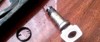
Installing a new part
The removal and assembly algorithm is the same, although the instructions for installing the cylinder mechanism have its own nuances. Before inserting a new cylinder into the core, the part is lubricated with a silicone substance and only then inserted into the handle. Further algorithm of actions:
- The return spring is inserted next to the cylinder.
- The functionality of the key is checked. It should turn easily in all positions.
- A pin is installed on the tip of the rotary rod. Connection is being made.
- The inner and outer panels are screwed on, the handles are fixed, and the plug is returned to its place.
- The main three screws are tightened from the inside.
You won’t have to change the lock cylinder for a long time if you carefully use the opening mechanism.