1200 rub. for the photo report
We pay for photo reports on car repairs. Earnings from 10,000 rubles/month.
Write:
The term breakdown of an ignition coil or spark plug tip means a breakdown in the weakest point of the housing or wire insulation due to a decrease in resistance, occurring in short periods of time. This is mechanical damage that leads to the appearance of cracks or melting. On the surface of the case, the breakdown site appears as black, burnt-out dots, longitudinal tracks or white cracks. Such spark piercing areas are especially dangerous in humid weather. This malfunction leads not only to failure of the mixture to ignite, but also to complete failure of the ignition module.
Often such places are not difficult to notice visually, but sometimes it is necessary to check the ignition coil, not with a multimeter or oscilloscope, but with a simple device made of two wires. When a damaged area is identified, the part is usually completely replaced, although sometimes it is possible to delay the replacement using electrical tape, sealant or epoxy glue.
What is ignition coil breakdown and its causes?
Let's take a brief look at what coil breakdown is, what it affects, and what it looks like visually. First of all, it should be recalled that the coil itself is a transformer that has two windings (primary and secondary), isolated from each other. The definition of breakdown is a physical phenomenon when, due to damage to the primary and/or secondary windings of the coil, part of the electrical energy falls not on the spark plug, but on the housing. This leads to the fact that the spark plug does not work at full power, and accordingly, the engine begins to “trouble” and its dynamics are lost.
Ignition coil device
There can be many reasons for the breakdown of the ignition coil - damage to the insulation of one or both windings, damage to the tip body, damage to its rubber seal (due to which water gets inside, through which electricity “sews”), the presence of dirt on the body (similar to water, current passes through it), damage (oxidation) of the electrode in the tip. However, most often the problem lies in the “wired” insulator, and therefore, to eliminate the problem, this place must be localized and insulated.
An interesting reason for the failure of ignition coil tips is the fact that when replacing a spark plug, in some cases, car owners, through carelessness or inexperience, can tear their waterproofing. This can lead to moisture getting under them and problems with engine operation. The opposite case is that when the car owner tightens the top nuts of the spark plug cups too tightly, there is a risk that engine oil from the engine will begin to penetrate into the plug housing. And this oil is harmful to the rubber from which the reel tips are made.
Also, the reason that spark breakdown occurs outside the cylinder is incorrectly set gaps on the spark plugs. This is especially true if the gap is increased. Naturally, the spark in this case has a detrimental effect on both the spark plug body and the rubber tip of the ignition coil.
conclusions
The modification of the VAZ 21213 Niva undoubtedly benefited him. The new engine and improved ignition system have made its operation even easier and more confident in harsh conditions.
ATTENTION!
The electronic catalog of spare parts intended for reference purposes only!
Our company does not sell all spare parts presented in this list. If there is a “Cost” link in the right column, these spare parts are on active sale. Availability in warehouses for details and prices, see the product card. If there is no “Cost” link in the right column, we do not sell such parts and do not accept orders for them.
Symptoms of a faulty ignition coil
Signs of a malfunction of the ignition coil are that the engine periodically “trips” (triggering is especially important in rainy weather, and when starting the engine “in cold weather”), “failures” occur when accelerating the car, when visually inspecting the coil, “paths” of electrical breakdown are observed, burning of contacts, signs of thermal overheating, the presence of a large amount of dirt and debris in the coil body and other, smaller faults. The most common cause of coil malfunction is a break in its primary or secondary windings. In some cases, their insulation is simply damaged. At the initial stage, the coil will work more or less normally, but over time the problems will worsen and the symptoms described above will appear to a greater extent.
There are several typical signs of an ignition coil breakdown. It’s worth mentioning right away that the malfunctions listed below can be caused by other reasons, so diagnostics should still be carried out comprehensively, including checking the condition of the ignition coils. Thus, symptoms of breakdown can be divided into two types - behavioral and visual. Behavioral ones include:
- The engine begins to "trouble". And over time, the situation gets worse, that is, the “tweaking” is expressed more and more clearly, the power and dynamics of the engine are lost.
- When trying to accelerate quickly, a “failure” occurs, and when idling, the engine speed does not increase sharply. There is also a loss of power under load (when transporting heavy loads, driving uphill, and so on).
- “Tripping” of the engine more often occurs in rainy (humid) weather and when starting the engine “cold” (especially typical for low ambient temperatures).
- In some cases (on older cars), the smell of unburned gasoline may appear in the cabin. On newer cars, a similar situation may occur when, instead of more or less clean exhaust gases, the smell of unburned gasoline is added to them.
When dismantling the ignition coil if it malfunctions, you can observe visual signs that it has completely or partially failed. So, these include:
- The presence of “breakdown tracks” on the coil body. That is, characteristic dark stripes along which electricity “strikes”. In some particularly “neglected” cases, scale occurs on the tracks.
- Change (turbidity, blackening) in the color of the dielectric on the ignition coil body.
- Darkening of electrical contacts and connectors resulting from their burning.
- Traces of overheating on the coil body. Usually they are expressed in some kind of “drips” or changes in the geometry of the body in some places. In “severe” cases, they may have a burning smell.
- High contamination on the coil body. Especially near electrical contacts. The fact is that electrical breakdown can occur precisely on the surface of dust or dirt. Therefore, it is advisable to prevent such a state.
The main sign of a coil malfunction is the lack of ignition of the fuel mixture. However, this situation does not always arise, since in certain cases part of the electrical energy still goes to the candle, and not just to the body. In this case, it is necessary to conduct additional diagnostics.
Well, on modern cars, in the event of a breakdown of the ignition coil, the electronic engine control unit (ECU) will notify the driver about this by activating the Check Engine lamp on the dashboard (and a misfire diagnostic code). However, it can also light up due to other faults, so this requires additional diagnostics using software and hardware.
The symptoms of malfunction described above are relevant if the engine has individual ignition coils. If the design provides for the installation of one coil, common to all cylinders, then the engine will stall completely (this, in fact, is one of the reasons why several individual modules are installed on modern cars).
Non-contact ignition system device
Contact ignitions are obsolete, but are still used in older cars.
On rear-wheel drive VAZ models, contactless was first installed on 2107. The BSZ device for carburetor engines consists of:
- Distributor. This is a device that is responsible for creating a spark at the right moment. It is also called the ignition system distributor.
- High voltage coil. This element in the ignition system receives low voltage from the battery, converts it and supplies high voltage. Therefore, high-voltage wires come from it. The coil consists of two windings. The primary one is made of a large cross-section wire (connected to the electrical part of the car via the ignition switch relay), the secondary one is made of many turns of thin wire (connected with a high-voltage wire to the distributor).
- Switch. This element of the contactless ignition system is responsible for the formation of a spark. In simple words, a switch is a signal amplifier. The switch is only available in the ignition system of internal combustion engines with a carburetor. By the way, SOLEKS is considered the best carburetor. On injection VAZ 2107, as well as on others, a switch is not needed, since its functions are performed by the on-board computer controller.
- High voltage and normal wiring. High voltage wiring must meet heavy insulation requirements.
- Terminals. Serve for connections and must be strong.
https://www.youtube.com/watch?v=SqqIBAU8osQ
Electronic and contactless ignition systems are the same device. It got its name due to the absence of a contact group in the system design. The ignition switch also has a contact group, which is a common cause of engine failure.
To install the BSZ with your own hands, you will need the following tools:
- Screwdrivers (flat and Phillips);
- Open-end wrenches 8, 10, 13 mm;
- Pliers (pliers);
- Candle key;
- Drill or screwdriver with a drill diameter of 3-3.5 mm. You will have to drill two holes in the body to secure the switch.
- A special wrench for rotating the crankshaft of an internal combustion engine or a regular open-end wrench of 30 mm.
This video covers all the nuances.
First of all, it is important to make sure that the problem is in the lock. Therefore, the spark plugs, distributor and ignition coil are inspected. Often these parts of the internal combustion engine become the reason for failures of correct operation. If breakdowns in them are excluded, then the ignition switch (IZ) should be replaced. Removal order:
- Disconnect battery.
- Remove the steering column.
- Mark the wires going to the 3Z contact area. Using a flat-head screwdriver, unscrew the bolts securing the switch to the steering column (left and right).
- Insert the key into position 0. By pressing the screwdriver, press the lock slightly through the hole (do not touch the key).
- Lightly pull the 3Z towards you and dismantle it. The ignition switch Niva 21213 is switched off according to the wiring diagram (the contact part is changed if required). To do this, be sure to remove the retaining ring with a screwdriver.
- Remove the key, install the contact part so that the wide protrusions of the body and the parts coincide.
- The remaining parts are assembled in the reverse order.
If you strictly follow the instructions and wiring diagram, no problems should arise. This is facilitated by the simplicity of the design. Moreover, the part can even be repaired if the damage is not critical.
It is logical that errors are possible when connecting contacts or incorrect installation of the lock itself. Therefore, it is necessary to test the protection in the installed state. You will need an ohmmeter and a voltmeter. Performance diagnostics:
- Checking the resistance between the terminals of the secondary winding: connect the probes to cylinders 1 and 4, then to cylinders 2 and 3. The data should approximately match. An error greater than 100 ohms indicates damage to the secondary winding.
- The wiring is checked with a voltmeter. The first control - one probe is placed on contact A, the second - on ground. Start the engine and record the data. Turn off the car and repeat the procedure with contact B. The readings should be about 12 volts.
- In addition, if there is no voltage, check the fuse, the possibility of broken wiring or corrosion of the contacts.
The last case is especially unpleasant, since you will have to check almost all the wiring, contact elements, etc. If there are possible suspicions about the electrical network, it is better to take the car to a professional auto electrician. Repairing it requires a thorough knowledge of the circuit and experience in finding defects.
| №1 | Rear fog lamp relay |
| №2 | Rear window heating relay |
| №3 | Low beam relay |
| №4 | High beam relay |
Some owners of classic cars of the VAZ 2101-07 family are constantly trying to improve, modify, add electronics and convenience. One of these improvements is the installation of contactless electronic ignition.
- Distributor. This is a device that is responsible for creating a spark at the right moment. It is also called the ignition system distributor.
- High voltage coil. This element in the ignition system receives low voltage from the battery, converts it and supplies high voltage. Therefore, high-voltage wires come from it. The coil consists of two windings. The primary one is made of a large cross-section wire (connected to the electrical part of the car via the ignition switch relay), the secondary one is made of many turns of thin wire (connected with a high-voltage wire to the distributor).
- Switch. This element of the contactless ignition system is responsible for the formation of a spark. In simple words, a switch is a signal amplifier. The switch is only available in the ignition system of internal combustion engines with a carburetor. By the way, SOLEKS is considered the best carburetor. On injection VAZ 2107, as well as on others, a switch is not needed, since its functions are performed by the on-board computer controller.
- High voltage and normal wiring. High voltage wiring must meet heavy insulation requirements.
- Terminals. Serve for connections and must be strong.
Also interesting: Chevrolet Niva starter does not turn
The ignition system is contactless. Consists of a distribution sensor, switch, ignition coil, spark plugs, ignition switch and high and low voltage wires.
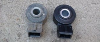
The ignition distributor sensor 3810.3706 is a four-spark type, with a contactless control pulse sensor and built-in vacuum and centrifugal ignition timing regulators.
The initial ignition timing angle at a crankshaft speed of 750–800 rpm should be 1±1° BTDC.
The distribution sensor performs two main functions: firstly, it sets the moment of spark formation depending on its initial setting, the number of revolutions of the crankshaft and the load on the engine, and secondly, it distributes high voltage pulses (“spark”) among the cylinders in accordance with the order of their operation - a rotor (runner) is used for this.
In order to avoid mistakes during assembly, the slider is installed on the support plate of the centrifugal regulator in only one position.
The slider has a 1 kOhm noise suppression resistor.
The operation of a contactless sensor is based on the Hall effect.
When the ignition is turned on, power supply is supplied to the sensor. When the sensor-distributor roller rotates, a steel screen with rectangular cutouts passes through the sensor gap.
While there is a screen plate in the gap, the voltage is removed from the control terminal of the sensor; as soon as there is a cutout in the gap, the voltage at the control terminal drops sharply.
Thus, the contactless sensor produces four rectangular pulses (according to the number of cutouts in the screen) for each revolution of the distributor shaft, which corresponds to the ignition moment in each of the engine cylinders.
You can check the functionality of the contactless sensor by assembling the circuit shown in the figure.
Slowly rotating the ignition distributor shaft, monitor the voltmeter readings.
The voltage should change sharply from the minimum (no more than 0.4 V) to the maximum (no more than 3 V less than the supply voltage).
A faulty sensor cannot be repaired (except for a break in the wires between the sensor itself and the block on the sensor-distributor housing).
If a steel screen with slots touches the sensor (determined by slight jamming or a scratching sound when the roller rotates, as well as visually after partial disassembly of the distributor sensor), check the axial play of the roller and the fit of the screen.
If necessary, replace the distributor sensor. The centrifugal regulator increases the ignition timing with increasing engine speed, coming into operation at 900–1400 rpm.
When the sensor-distributor roller rotates, the regulator weights diverge under the action of centrifugal forces, overcoming the resistance of the springs, and shift the support plate of the centrifugal regulator clockwise relative to the roller.
For optimal operation of the regulator, the springs have different stiffnesses.
A stiffer (thicker) spring comes into operation later, approximately in the middle of the full stroke of the plate - therefore it is put on the stand with a gap, while a softer (thin) spring is always tense.
The maximum movement of the support plate is limited by the cutout in it and is about 12° along the distributor, which corresponds to an ignition timing angle of about 24° along the crankshaft.
When inspecting the centrifugal regulator, make sure that the weights move freely on the axles, their damper plastic rings are not lost, the thin spring is tensioned, and the support plate returns under the action of the springs to its original position. If necessary, lubricate the distributor shaft with a few drops of engine oil.
The vacuum regulator increases the ignition timing depending on the engine load. It consists of a vacuum chamber with a steel spring-loaded membrane, which is connected by a rod to the base plate of the proximity sensor.
Under the influence of vacuum, the membrane bends, overcoming the resistance of the spring, and turns the support plate counterclockwise.
The maximum movement is limited by the cutout on the rod and is about 9° at the distributor (18° at the crankshaft).
The vacuum for the operation of the vacuum regulator is taken from the hole in the mixing chamber of the carburetor opposite the throttle valve of the first chamber. When the damper is partially opened (partial load), the vacuum behind it is large, and the regulator shifts the moment of spark formation as much as possible towards the advance.
How to check a coil for breakdown
You can check for breakdown of the ignition coil in one of 5 ways, but as a rule, the average car owner has the opportunity to use only three of them. The first is a visual inspection, because often the breakdown site is visible to the eye; the second is a check with a multimeter, and the third, and the most reliable quick method, if nothing is visually noticeable, is to use a simple ignition system tester (it’s easy to do it yourself).
Ignition system diagnostics
Recommendations for diagnosing the ignition system (spark plugs, wires, coils, module). Instructions on how to check the ignition units of a car with your own hands Read more
To check the operation of the ignition system, first of all, it makes sense to use a program to read errors from the ECU. Usually in such cases it shows errors from the P0300 group, indicating misfire in one of the cylinders. However, please note that in this case, errors can be caused not only by faulty coils or spark plug tips. Therefore, in order to make sure that the fault is with one of them, it makes sense to move the problem unit to another cylinder, erase errors from the ECU memory and carry out diagnostics again.
If the problem is in the coil (we are talking about an individual coil), then the situation with errors will repeat, but indicating a different cylinder. True, when this is precisely a breakdown of the coil, and such that gaps appear, then you can already understand by the vibration of the engine, see with your eye a broken insulator track, or even hear a characteristic crackling sound with your ear. Sometimes at night, in addition to a crackling sound, you can also see a spark appearing.
Visual inspection
The next way to determine a breakdown of the ignition coil is to dismantle it and visually inspect it. As practice shows, on the coil body it is usually not difficult to find the very “path” of breakdown along which the spark “sews”. Or you should pay attention to chips, potholes, and geometry violations in the reel body that were not there before.
Measuring parameters
There are two mandatory methods for checking the condition of the ignition coil - checking for spark and checking the insulation resistance of both windings (low and high voltage). To measure the parameters, you will need a working spark plug and a multimeter with the ability to measure insulation resistance. But the most reliable way is to use a spark generation tester, only with a slight modification, so that you can move the conductor along the coil body and look for the weak point of the insulation that breaks through.
Homemade spark tester
The most interesting and reliable method for checking the breakdown of the ignition coil is to use a special homemade probe. It helps when the defect is not visible visually, checking the resistance of the windings did not reveal the problem, but there is no way to use an oscilloscope. To make a spark tester you will need:
- medical disposable 20 cc syringe;
- two pieces of flexible copper wire (PV3 or similar) with a cross-sectional area of 1.5...2.5 mm², each about half a meter long;
- small crocodile mount;
- a known good spark plug (you can take a working used one);
- a piece of heat shrink with a diameter slightly larger than the total diameter of the existing copper wire;
- a small piece of flexible wire;
- electric soldering iron;
- manual or electric hacksaw (grinder);
- a heat gun with silicone pre-charged into it;
- a screwdriver or an electric drill with a drill with a diameter of 3...4 mm.
- assembly knife.
The manufacturing process sequence consists of the following steps:
- Using a mounting knife, you need to remove the “nose” from the syringe, where the needle is put on.
- Using a hand saw or grinder, it is necessary to cut the thread on the candle in such a way as to remove the part of the body on which this thread is applied. As a result, only the electrode will remain at the bottom of the spark plug.
- In the upper part of the syringe body, it is necessary to make a hole of such a diameter that a pre-processed spark plug can be inserted there.
- Using a heat gun, solder the junction of the candle and the body of the plastic syringe along the ring. Do this carefully to make good hydraulic and electrical insulation.
- The syringe piston in its front and rear parts must be drilled using a screwdriver.
- It is necessary to insert two previously prepared pieces of flexible copper wire into the drilled hole in the lower part. To the opposite end of one of them you need to solder the prepared crocodile mount using a soldering iron. The opposite end of the second wire needs to be lightly stripped (about 1 cm or less).
- You need to insert a prepared metal wire into a similar hole in the upper part.
- Approximately in the middle of the piston, connect the copper wires and wires together into a single contact (solder).
- The junction of the wire with the wire must be soldered using a heat gun for mechanical strength and reliability of contact.
- Insert the piston back into the syringe body so that the wire at the top of the piston is at some distance from the spark plug electrode (the distance will be adjusted later).
How to determine ignition coil breakdown with a spark tester
After a homemade tester has been made to find the location of the penetration, the procedure itself must be performed according to the following algorithm:
Finding a breakdown using a homemade tester
- Connect the ignition coil being tested to the spark plug in the tester you made.
- Disconnect the connector at the corresponding injector (where the coil was disconnected) so that fuel does not flood the spark plug well during testing.
- Connect the wire with an alligator clip to the negative terminal of the battery or simply to ground.
- Set the gap in the syringe to about 1.2 mm.
- Start the engine. After this, a spark will appear in the syringe body between the spark and the wire.
- The stripped end of the second wire (connected in parallel) must be moved along the coil body. If there is a penetration on it, then a spark will appear between the body and the end of the wire, which can be clearly seen. This makes it possible not only to verify its presence, but also to determine the location of its occurrence for further troubleshooting.
- Repeat for all coils in turn, not forgetting to disconnect and connect the corresponding fuel injectors.
The verification method is simple and universal. With its help, you can not only find the place where the spark “sews” across the body, but also determine the general operating condition of the ignition coil itself.
This is done by adjusting the gap between the spark plug electrode and the wire on the syringe plunger. At the initial stage, a minimum gap is set with a value of about 1.2 mm and gradually increases. The value of the gap at which the spark disappears depends on the engine size, the type and condition of the ignition system and other factors. On average, for engines with a volume of about 2 liters or less, the distance at which the spark should disappear is about 12 mm, but this is conditional. In general, when checking all individual ignition coils, you can simply compare their operation with each other and identify the faulty element, if present.
Replacing the Niva 21214 timing chain on an injector with your own hands, video
Here we will talk about independently replacing the timing chain drive on a Niva 21214. The timing belt affects the operation of the entire car, so the importance of this unit should not be underestimated. Replacing a chain drive is a rather complicated process, which, however, can be done by any car enthusiast, provided that he follows the instructions and shows a little diligence.
A chain has significant advantages over a belt drive. These include, first of all, its reliability. While a belt can break, this rarely happens with a chain. Usually it just stretches. It lasts much longer than the belt, which means it needs to be changed less often. But still, the chain does not last forever, and after a while it also has to be replaced with a new one. When replacing the chain yourself, it is very important to set the marks correctly and follow safety precautions.
When to change the timing chain?
The manufacturer does not give clear recommendations regarding the timing of replacing the timing chain on the Niva. Experts assure that the need for replacement may arise no earlier than after 100,000 km. But it is very important to periodically carry out diagnostic procedures for chain transmission. It may well happen that the chain weakens. This will be noticeable by the characteristic sound that the running engine will make. First you need to try to tighten the chain. If this cannot be done in the usual way, replacement becomes necessary. In this case, you can contact a service center, where this repair will be carried out by professionals, or you can try to change the chain yourself. The latter option is preferable in terms of savings and gaining the necessary experience.
If the mark on the camshaft gear does not match the mark on the bearing housing, it's time to take action. The chain drive also needs to be replaced if chips or cracks appear on it. All this suggests that your chain has served its intended life and it is time to replace it.
So, you have decided that you will make the replacement yourself. What do you need to do next? First of all, go to the store and buy a new chain there. You can check the quality of the chain you are purchasing. We take the chain and place it flat on our palms. If its sagging exceeds 1 cm, you better look for consumables elsewhere. In addition to the chain itself, you will also have to buy a set of oil seals, a tensioner, dampers, and a set of gaskets. Then we prepare the tools that will be useful in the work and begin the repair.
Replacing the chain drive
- Place the car on a level surface. Open the hood. Disconnect the battery. Remove the air filter.
- The choke cable should be disconnected and moved away. It is also necessary to disconnect all electrical drives and pipes.
- Remove the fan, generator belt and pump roller. The belt should be thoroughly examined. If deep cracks or other damage is found on it, it must be replaced with a new one. Remove the tray protection and thoroughly clean its cover.
- Remove the valve plug. Unscrew the camshaft sprocket screw.
- Take a wrench and unscrew the ratchet nut.
- Now we begin to rotate the crankshaft until the marks on it and on the engine casing completely coincide. Make sure that the marks also match on the bearing housing and camshaft sprockets.
How to fix a breakdown
As for the question of how to fix a breakdown, there are two options - fast (“field”) and slow (“garage”). In the latter case, everything is simple - it is advisable to completely change the coil, especially if the breakdown is significant. As for quick repairs, either electrical tape or glue is used for this.
Isolating a damaged coil
The most interesting question for car owners in this context is how to eliminate a breakdown of the injection ignition coil? In the simplest case, that is, if there is a small spark breakdown on the body (and this is the most common type of breakdown), after localizing this place you need to use insulating materials (insulating tape, heat shrink, sealant, epoxy glue or similar means, in some In cases, even nail polish is used, but the polish should only be colorless, without any paints or additives), and isolate the place (path) of the breakdown. It is impossible to give universal advice; it all depends on the specific situation.
When performing repairs, it is necessary to clean and degrease the area of electrical breakdown before applying a protective insulating layer to it. This will increase the resistance value of the resulting insulation. If, when the insulation is damaged and there is a breakdown, liquid appears in the coil (usually from a damaged seal), then it makes sense to additionally use dielectric grease.
Well, in the most severe case, you can, of course, install a new coil. It can be original or not - it depends on the price. Many car owners are saved by the so-called “dismantling shops”, that is, places where you can buy spare parts from disassembled cars. They are cheaper there and you can easily find high-quality components.
Finally, a few words about preventive measures that will allow you to get rid of troubles and operate the reel for a very long time and without problems. The simplest measure in this context is to use heat shrink of a suitable (large) diameter, which must be applied to the surface of the tip of the ignition coil. The procedure is simple, the main thing is to choose heat shrink of the appropriate size and diameter, and also have a hair dryer (preferably a construction hair dryer) or some kind of gas burner on hand. However, before applying heat shrink, do not forget to clean and degrease the working surface of the tip. This procedure can also be used not as a preventive measure, but rather as a repair measure.
Also, for prevention, it is advisable to keep the coil housing, and other engine elements, clean so that there is no “sparking” through dirt and dust. And when replacing spark plugs, always use dielectric grease for spark plugs.
The ignition module (IM) of the Niva-Chevrolet car is highly reliable and, most often, provides sparking over many tens of thousands of kilometers. However, if it fails, it is difficult to diagnose due to the lack of obvious signs. The decent cost of a module does not always allow it to be replaced with a new one, which is called “blindly”. First you need to reliably verify that the old one is faulty. Read the article about how to check the ignition module of a Niva-Chevrolet.
Finding the origin of the problem
First you need to check the performance of the spark plugs, and this check may indirectly indicate a coil malfunction.
To check, you just need to unscrew the spark plugs, insert them into the tips of the high voltage wires, massage them and turn the crankshaft several times with the starter. In this case, you should look at the spark that forms between the electrodes.
If it is discovered that a spark plug is not working correctly and the spark in it is formed intermittently, it should be replaced and a known good one installed in its place.
If a working spark plug works intermittently, check the high voltage wire.
If the interruptions persist even when the wire is replaced, then in carburetor cars the distributor is inspected next, and only then the coil.
In injection cars equipped with a module, there is no such distributor, so you can immediately start checking the module.
Checking these elements will not be particularly difficult, and the only equipment you will need is a multimeter with the ability to operate in ohmmeter mode, with a measurement range of up to 200 MOhm.
To make it more clear, let’s look at how these ignition elements are checked on different cars.
Briefly about the design
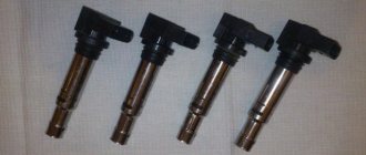
The main purpose of any MZ is to convert a low-voltage signal into a high voltage sufficient for normal sparking in the cylinders. Therefore, structurally, the Niva-Chevrolet ignition module is a pulse transformer. A signal from the electronic control unit (ECU) is supplied to its input, and a voltage of about 20 - 30 kV is removed from the output. The module has a connector for connecting the low-voltage part and four sockets into which the so-called armored wires are inserted.
High voltage is supplied to two cylinders at once. In this case, 90% of the energy is spent on the formation of a spark where the compression stroke ends. The working mixture in it is under high pressure, which means it has high conductivity. Thus, the module consists of two independent ignition coils.
Connecting high voltage wires
The sequence of connecting the high-voltage wires plays a huge role, since the spark in the cylinder is supplied in a certain order, which is indicated by the crankshaft position sensor. As soon as the piston reaches TDC, a spark is supplied to it to ignite the air-fuel mixture.
Below is a diagram of how to connect high-voltage wires on a Niva.
Where is the Ministry of Health located?
The location of the Niva-Chevrolet ignition module was not chosen very well. It is attached to the bottom of the cylinder block. Thus, the module is exposed to two negative factors at once:
- Corrosion. This is facilitated by the low location. During operation, moisture often gets into the MH.
- High temperature. Mounting the module on the cylinder block forces it to operate at temperatures close to 100 degrees.
The second factor is the most critical for MH. The manufacturer guarantees normal operation of the device up to 120 C°. This kind of temperature under the hood is rare. But constant exposure, even to lower values, significantly reduces the service life of the MH. Therefore, conscientious owners move the module to a place with more benign conditions. Most often, on the partition of the engine compartment.
Maintenance Tips
The factory instructions require troubleshooting the ignition system in the following sequence:
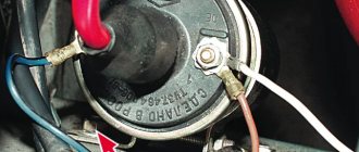
Ignition system: wiring for Niva 21213
- From the ignition switch (terminal 15), connect the wire to the coil (terminal +B) to a test lamp;
- Connect its negative terminal to ground;
- Turn on the ignition - turn the key in the lock to position “II”;
- If the control lamp lights up, then the circuit is working. If not, look for damage to the wire;
- With the ignition on, pull out the central wire from the coil from the distributor;
- Bring its metal tip to the cylinder block so that a gap of 3-4 mm forms between them;
- Turn on the starter for a few seconds;
- If the spark jumps, the coil is working.
Tip: you can quickly check the switch in one way - take it from a working car. If the car starts with the new switch, then you need to buy a new one.
Varieties
During its production, Shniva was equipped with two types of modules.
- MZ from a VAZ 2112 car. Installed until 2006. It includes a spark control system.
- The module is from a VAZ 2111. It is controlled by signals from the ECU, therefore, in essence, it is a regular ignition coil.
Please note that the modules are not interchangeable. This is due to their different designs. You can determine which ignition module on a Niva-Chevrolet by its appearance. The old one has large dimensions and weight, and most importantly, unlike the new one, there are not three, but four contacts on the primary winding connector. At the same time, the process of checking the Niva-Chevrolet ignition module will be considered using the example of a new module.
Useful video
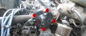
The most correct method (not the “poke method”). Remove the valve cover and turn the crankshaft until the mark on the camshaft coincides with the casting at the top (mark on the inside of the sprocket). Set the mark on the crankshaft 9 degrees earlier than the long mark (TDC). The nearest short mark is -5g, the second -10g. That is, the mark on the pulley will be almost on the farthest short mark, slightly shifted towards the first short mark.
Place the distributor in place so that the slider is directed towards the FOURTH cylinder (according to the inscriptions on the distributor cover). In this case, the latches should be approximately parallel to the motor. Lightly press the distributor with the nut, but so that it can be turned by hand. Place the cover and the wire with the grounded spark plug on the terminal of the fourth cylinder, also put the wire on the coil and on the central terminal (do not forget about the Hall sensor).
Symptoms of a problem
As already mentioned, symptoms of a faulty ignition module are also typical for many other components of the car. There are almost no signs that directly indicate MH. This significantly complicates repairs. However, with experience, conclusions about a malfunction of the Chevrolet Niva ignition module can be drawn from the following symptoms.
- Two cylinders are not firing at once. This is the only sign that, although not always, indicates MH. The likelihood of this increases if cylinders 1 and 4 or cylinders 2 and 3 are not working at the same time.
- Idle speed “floats”.
- Diagnostics shows misfires in all cylinders.
- As the engine warms up, its power drops and interruptions appear.
- The CHECK ENGIN alarm comes on.
It should be noted that a complete failure of the motor, in which the engine does not start at all, happens very rarely. Basically, this symptom of a malfunction of the Niva-Chevrolet ignition module indicates damage to the low-voltage part of the wiring.
How module malfunctions are shown by diagnostics
By visiting a service station or using amateur diagnostic equipment (error scanner, a special application and an adapter for computer diagnostics via Bluetooth), you can also find out that the “root of evil” is in the ignition module.
In this case, the following error codes should be displayed:
- P3000 (P3001, P3002, P3003, P3004) - ignition in the cylinders does not work;
- P0351 - break in the winding of a pair of cylinders 1-4;
- P0352 - break in the winding of a pair of 2-3 cylinders.
Causes of damage
Most often, the Niva-Chevrolet ignition module fails due to overheating caused by its poor location in the engine compartment. This simply leads to a break in the secondary winding of the pulse transformer. However, this can happen for other reasons, namely:
- use of faulty high-voltage wires;
- use of spark plugs other than those recommended by the manufacturer;
- checking the spark by shorting the armored wire to the car body;
- manufacturing defects.
Thus, one of the main reasons for module failure is the notorious “human factor”. The reason for this is incorrect diagnosis and operation of the MH. Test methods that are acceptable for the ignition coil of a carburetor engine are most often not suitable for modern modules and will most likely cause failure.
We install ignition on a carburetor Niva VAZ 21213
It is clear to anyone, not even a car owner, that without the ignition the car will not start or drive (criminal options are not considered). Depending on the car manufacturer, repairs or replacement of parts occur at a car service center or independently. Installing the ignition on a VAZ 21213 NIVA carburetor is one of those processes that the owner can carry out himself. This approach will save money and give you personal experience in repairs.
It is clear to anyone, not even a car owner, that without the ignition the car will not start or drive (criminal options are not considered). Depending on the car manufacturer, repairs or replacement of parts occur at a car service center or independently. Installing the ignition on a VAZ 21213 NIVA carburetor is one of those processes that the owner can carry out himself. This approach will save money and give you personal experience in repairs.
Main causes of malfunctions.
Mostly, malfunctions occur due to damage to the winding. Since high voltage current is generated in it, over time, when using low-quality materials, damage to the wire sheath, breakage or rupture of turns may occur. This can happen for several reasons:
- Use of faulty high-voltage wires.
- Spark plugs that do not match the vehicle parameters are used.
- Solder failure due to high motor vibration
- Moisture getting inside the case
- Condensation Formation
So, for example, if there is damage in the armor wires, then the coil impulse is not fully used, and it looks for another output, as a result of which it breaks through the secondary winding, where the wire cross-section is lower.
This problem manifests itself gradually, since the coils begin to fail gradually and one of them will continue to work for some time. Therefore, if the following symptoms appear, you must immediately check the functionality of the module:
- the engine has difficulty gaining operating speed
- floating idle
- the engine is running rough - there is no spark in one of the cylinders
- jerking while driving
These reasons may be associated with other breakdowns, but when conducting diagnostics, one should not forget about the Niva Chevrolet ignition module. If you suspect the functionality of a component, you must check the device. Diagnostics begins with checking the power contacts. They may be oxidized or the wiring may be broken. If this does not bring results, then you need to dismantle it to check it using additional instruments.
Procedure for checking the ignition module
First of all, you will have to get a multimeter. There is no need to look for any high-precision and expensive instruments. The usual Chinese one will suffice. The main thing is that it has a digital display, this will greatly simplify the measurement. The optimal multimeter in terms of price and functionality is the DT 830 and its numerous modifications. This is one of the most common and easy to use devices. The verification process will be discussed using his example.
First of all, you need to make sure that the primary winding of the Niva-Chevrolet ignition module is intact. For this:
- the switch on the front panel of the device is set to the 200 Ohm position;
- disconnect the connector from the module, remove the high voltage wires;
- sequentially measure the resistance between the middle and extreme contacts of the terminal block;
- The device readings should be within 0.5 Ohm.
The accuracy of a multimeter, of course, is not enough to measure such small quantities, but to check the primary winding for an open circuit, this is quite enough.
The next step is to measure the resistance of the secondary. Sequencing:
- set the range switch DT-830 to position 20 K;
- The probes of the device must first be placed between the high-voltage terminals of cylinders 1 and 4, then between 2 and 3;
- the device display should display 5.4 kOhm.
It should be said that it is possible to diagnose a malfunction of the Niva-Chevrolet ignition module only if the readings differ significantly from the norm, or, more often, if “1” lights up on the device indicator. This means an infinitely large resistance, in other words, a winding break.
Also, the cause of non-working coils can be a banal contact failure in the incoming connector.
How to check the ignition module
Such damage is detected when the rear cover of the module is removed.
Manuals → Chevrolet → Niva (Chevrolet Niva). Check the resistance of the primary winding of the ignition coil using...
Ignition module All hope is that by changing the ignition module, the car will drive and we will still get to mother-in-law Shuruya back to the store and buy an ignition module from MZ, it is not cheap - it costs rubles, domestic. Usual for 8-valve Chevy Niva engines, turnkey 21 mm. Soldering failure due to high vibration of the engine Moisture getting inside the housing Formation of condensation So, for example, if there is damage in the armor wires, then the coil impulse is not fully used, and it looks for another output, as a result of which it breaks through the secondary winding, where the wire cross-section is lower.
Tomorrow we are planning to go to my mother-in-law's, a kilometer away, so it was still a good idea, what if there were no wires?
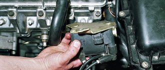
Installation in the cold took several hours. I removed the old ignition module, its bracket and installed a new one.
Checking with a multimeter
- The check is carried out on the removed device and begins with inspecting the condition of the terminals to which the high-voltage wires are connected.
- The probe is installed on pin D, the black one is shorted to ground. In 20V voltmeter mode, the device should show 12 volts.
- Then we switch the device to resistance measurement mode, and install the red and black probes on contact D and ground, respectively. A normally operating device should have a reading of less than 1 ohm.
- We check contacts A and B one by one. The device is switched back to voltmeter mode and readings are taken. If they are no more than 0.3V, then the device is considered working.
If any measurements show deviations from the norm, then the device is considered faulty. The continuity of the circuit should be checked.
We carry out the adjustment ourselves
- The first step is to install the cylinder in the correct position. Installation is carried out so that the mark on the pulley is exactly at 0 degrees.
- Set how the slider is positioned. It should be aimed at the first pin in the cylinder.
- Use a strobe light and make sure the ignition is working properly.
- Make the electrical connections in the battery: minus to ground, plus to plus.
- The sensor must be connected to the high-voltage wire on the cylinder. The mark should connect to the crankshaft pulley.
- Start the engine at low speed (up to 800 rpm). Use a stroboscope to illuminate the pulley, and if the mark coincides with the middle mark, then the ignition is set correctly.
- Otherwise, the engine should be turned off and the meter should be loosened. In order to decrease the angle, turn the sensor clockwise; to increase it, turn it counterclockwise. Record and test the calibration again with the ignition on.
- Next, you should perform manipulations with the distribution sensor. Open the lid. Match the stator and rotor mark.
- Start the engine, bring the temperature to 75-80 degrees. When the speed is 50 km/h, sharply press the gas pedal.
- If the ignition was installed correctly, a short-term detonation will occur when you press the gas.
Also interesting: Installing a towbar on a Chevrolet Niva
Then there are two possible developments: early and late ignition. Let's consider solutions for both cases:
- In the case of late ignition, when there is no detonation, you should change the position of the sensor clockwise.
- In the case of early ignition, when detonation lasts longer than necessary, the sensor is rotated counterclockwise.
Niva 21213 can be subject to adjustment of the starting system by the gap at the edges of the valves, if the carburetor is removed, or by the crankshaft speed directly on the car. In the first case, the gap at the location of the lower edge (in the direction of air movement) from the throttle valve is set to a width of 1.1 mm.
It is adjusted with a screw that has a 0.7 cm hexagon on the head and a slot from the shank. This operation is carried out with the cam lever turned counterclockwise from the starting system control (all the way). In the same position, the gap at the lower edge of the air damper is set to 3 mm using a screw in the cover from the diaphragm mechanism in the starting system (you need to loosen the lock nut).
The principle of powering a carburetor engine Adjusting the Niva starting system directly in the car saves time: You need to remove the air filter from the engine, pull the control lever towards you from the air damper, and start the engine. When the air damper is forced to open (by touching a flat screwdriver to a third of its full angle of rotation) using a screw (next to the lever on the axis from the throttle valve from the first chamber), the initial rotation speed is set to 2.08.mar.0 thousand.
revolutions per minute (on a warm engine). Remove the screwdriver, lower the air damper and, using the screw stop (next to the diaphragm), set the frequency to be 100 rpm lower than the original one (you need to select the appropriate position of the air damper). The screw can then be secured using a locknut.
If you have a gas analyzer, then the carburetor adjustment in the starting system part can be done based on the amount of CO (carbon monoxide) in the exhaust gases. If, with the choke control lever fully extended, the gas rate is 8%, then everything is in order. If there is less gas than this value, then the screw on the cover of the diaphragm mechanism is tightened; if there is more, it is unscrewed and repeated measurements are taken.
It is necessary to adjust the idle speed of the Niva 2121 so that there is less carbon monoxide in the exhaust gases and so that the engine runs stably. At service stations, such work is carried out with gas analyzers on the MV. In the garage, adjustments can be made using the tachometer.
Adjusting the device For these purposes, on a warm engine, pierce the plastic plug with a screwdriver, then the quality screw is rotated in different directions until the maximum idle speed is reached. Then, using the quantity screw (has a ribbed plastic handle), you need to set an increased speed (50-70 rpm.
Spark plug.
On the Niva Chevrolet, the spark plugs are closely related to the previous device. And if they malfunction, all the same problems as described above are possible. Spark plugs fail especially often in winter. This is due to the fact that the car is not used so often and mainly for short trips. Due to the low ambient temperature, the candles do not warm up to the maximum temperature at which they self-clean from carbon deposits.
If problems occur, it is necessary to replace the spark plugs in a timely manner so that this does not affect the performance of other system components. Spark plugs for the Chevrolet Niva must be purchased specially for eight-valve injection engines. When purchasing, you should pay attention to the gap between the electrodes. It should be no more than 1.5 mm. If this distance is greater, this will affect the duration of the candle.
Selection of BSZ
When purchasing a new BSZ, you should pay attention to the presence of the components of the entire kit. The factory kit should contain:
- Distributor (main distributor). The code for engines 1.5 and 1.6 is 38.37061. For 1.3 engines, the number will be 38.3706–01, because the height of the 1.3 engine block is lower and the distributor shaft is shorter.
- Switch number 36.3734 or 3620.3734.
- High voltage coil (reel). Marking 27.3705
- Thin wires with connectors.
In appearance, the BSZ kit for the VAZ 2121 NIVA is very similar. But it’s better not to install this kit on a VAZ 2107 or a VAZ 2106, because the characteristics of the “six” and “seven” are very different from the “Niva”. Distributor brands for Niva: 3810.3706 or 38.3706–10.
The best manufacturer of electronic ignition systems for old VAZ cars is. The production capacity base is located in the city of Stary Oskol. According to reviews from car owners of classic BSZ SOATE models, this is an excellent option.
The best manufacturer of electronic ignition systems for old VAZ cars is. The production capacity base is located in the city of Stary Oskol. According to reviews from car owners of classic BSZ SOATE models, this is an excellent option.
Candle making options:
To increase productivity when creating these products, some technological features are used, which in theory can increase productivity, and as a result, the highest quality fuel combustion:
- Platinum coating. Allows you to increase the service life up to 50 thousand kilometers due to the fact that the surface becomes more resistant to the combustion products of the fuel mixture.
- Multi-contact spark plugs. Typically used in cars that are operated in regions with predominantly low temperatures. Such products make it possible to improve the starting of a cold car in the morning. In summer, it is recommended to replace them with regular ones.
incorrect Consequences of installation and adjustment
- Characteristic extraneous clicks appear in the engine, which become louder as the vehicle speeds up.
- The engine is even unstable at idle.
- The acceleration time of the car increases significantly because the engine reacts poorly to the gas pedal.
- The acceleration occurs in jerks, during which clouds of black smoke can fly out of the exhaust pipe.
- The wear of the valves is accelerated many times, and if the desynchronization of the shafts is too great, the valves are deformed and their seats are broken.
- Incorrect adjustment can also lead to an open circuit. The timing belt, in turn, can break, the radiator fan and other parts of the engine.
- The engine constantly overheats, and the consumption of engine oil and antifreeze can increase significantly.
it can be seen As from this article, correctly set timing marks are the key to long and uninterrupted operation of Nothing. there is no complicated engine in this, even a novice car enthusiast can do it
It is important not to follow or rush the above sequence of actions, but you also need to try not to drop the lock washers of the pan into the engine sprockets. Because it will be very difficult to get them from there
Long gone are the days when the world's first car rolled off the assembly line. It was equipped with a new injection system. The production of these machines today has increased 10-20 times. As you understand, we are talking about cars with injection systems. Let's find out how to set the ignition timing on the injector.
Today, 80 percent of people become owners of just such cars
Therefore, the ability to configure the ignition system is regarded as a very important advantage. It will allow you to always stay on the move, save money on repair services and fuel.
Tools and Diagnostics
ATTENTION! A completely simple way to reduce fuel consumption has been found! Don't believe me? An auto mechanic with 15 years of experience also didn’t believe it until he tried it. And now he saves 35,000 rubles a year on gasoline! Read more". Tools are an important part of any job.
They will be needed to make adjustments to the process of issuing SOP. Mandatory tools include screwdrivers, a measuring instrument, keys and preferably a laptop with a specially installed program designed for diagnosing injection-type power units
Tools are an important part of any job. They will be needed to make adjustments to the process of issuing SOP. Mandatory tools include screwdrivers, a measuring instrument, wrenches, and preferably a laptop with a specially installed program designed for diagnosing injection-type power units.
First, you should know that on an injection engine, electronics are responsible for driving the car. It is subordinate to the head – the computer system. Conducting quality testing of all components of the injection system is the first thing to do.
Here's how it's done:
- the ignition is turned on;
- the supply of fuel by the electric fuel pump is checked (the characteristic sounds of activation of the pump performing the injection should be heard).
If there are no sounds of the fuel pump operating, you need to check the relay that controls the operation of the pump.
You should also pay attention to the instrument panel, on which the indicator may indicate. If this is the case, then you need to connect a laptop with a special program to the BC system
It will help you analyze errors and display them in a list.
If no problems are identified at this stage, then it’s time to start the internal combustion engine. On a functioning engine, the throttle assembly is checked first.
Here's how it's done:
- first, an external inspection of the sensor, which is responsible for the position of the damper, is carried out;
- then the wiring condition is tested;
- if everything is in order, it would not be superfluous to measure the voltage of the entire circuit and sensor using a measuring device;
- the obtained values must be compared with the standard indicators specified in the vehicle repair manual.
A normal current value can be considered to be in the range of 0.45-0.55V. The current value should not exceed 12 V, and the throttle opening degree should not be more than 1%. If deviations are noticed, then you need to adjust the throttle drive so that it closes the damper entirely.
Next, you need to press the gas pedal all the way, re-measuring the indicators this way. The damper open level should be 90%. As for the sensor voltage, the voltage must be 4.5 V.
Throttle actuator tuning is considered an important part of the work included in the diagnosis. It allows you to simultaneously set up a node and check the consistency of the values.
In order to adjust the drive you need to:
- disable the RDPV (sensor responsible for additional air flows);
- half open the throttle;
- make adjustments so that the damper completely covers the hole.
How to restore
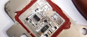
Opening the aluminum plate, you will find a small printed circuit board on which the active components are located. It is coated with transparent silicone. It will need to be removed as it will interfere with repairs.
Pay attention to the wires that connect the board and connector pins. They are aluminum, and this metal undergoes destruction much faster than copper. All these wires will need to be replaced
Some motorists who repair modules use wires that are used in mice for personal computers. But you need to get used to working with them - they are covered with paint
All these wires will need to be replaced. Some motorists who repair modules use wires that are used in mice for personal computers. But you need to get used to working with them - they are covered with paint.
In general, the diagram of the entire module is simple, it contains:
1. Two BU931 transistors (you can use the domestic analogue of KT848A, it performs well and is much cheaper).
2. Two SGS-THOMSON switches (model L497D1).