Removing and installing a caliper on a VAZ 2114-2115
The front brake calipers on the VAZ 2114-2115 have to be removed quite rarely, and replaced even less often. But there are cases when the clamping bracket mounting bolts rust so badly that when unscrewed they simply break off. Many people do not drill and replace the caliper with a new one. In order to remove it from the car, you will need the following tool:
- Head 19
- Driver and ratchet handle
- extension
- brake pipe wrench
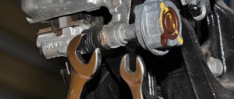
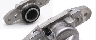
So, after the car is jacked up and the front wheel is removed, it is necessary to spray the caliper mounting bolts with penetrating lubricant from the back side. Then you should unscrew the brake hose, as shown in the photo below:
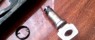
Lift it up and secure it so that the brake fluid does not leak out of the reservoir. Now you can unscrew the two caliper mounting bolts:
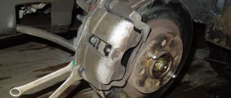
When the effort is not so great, it is better to use a ratchet:
After this, you can lift the caliper assembly with pads up, since nothing else holds it.
If you are changing the entire assembly, then buy a new mechanism and install it in the reverse order. After this, you will have to bleed the brakes, as air may form in the system, which will lead to poor braking.
Source
Examples of prices for current items
When buying a caliper for a VAZ 2109-2115, you can operate with the available amount, since there are quite a lot of good quality analogues to choose from, namely:
- Caliper assembly, R13 TRIALLI – RUB 1,880 .
- ATE assembled with a ventilated moving bracket – RUB 2,480 .
- LUCAS with an extended hose (without adapter) – RUB 4,050 .
- LADA (standard set for R13 wheel) – 4,270 rubles .
The choice of calipers is represented by more than 17 analogues, 2 original brands and 3 brands operating under AvtoVAZ license. Consequently, the price may change based on the financial policy of the manufacturer, as well as the final cost of the caliper.
Removing the caliper VAZ 2114
Removal and installation
Withdrawal. Raise the front of the car and place it on stands and remove the wheel. Unscrew the pipeline fitting and disconnect the flexible hose from the line; Plug the holes in the hose and tube to prevent brake fluid from leaking. Remove the hose from the guide bracket.
After unscrewing the two bolts that secure the shoe guide to the steering knuckle, remove the guide assembly with the caliper and working cylinder.
Installation of the brake mechanism is carried out in the reverse order of removal. After installation, restore the brake fluid level in the reservoir and bleed the hydraulic drive system to remove air.
Disassembly and assembly
Rice. 6-20. Unscrewing the cylinder mounting bolt: 1 – cylinder mounting bolts; 2 – cylinder; 3 – bolts connecting the cylinder with the caliper
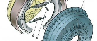
Rice. 6-21. Parts of the front wheel brake mechanism: 1 – wheel cylinder; 2 – fitting for bleeding the brake drive; 3 – sealing ring; 4 – piston; 5 – protective cap; 6 – retaining ring; 7 – caliper; 8 – pad guide; 9 – brake pads; 10 – protective cover; 11 – guide pin; 12 – guide pin fastening bolt; 13 – brake hose; 14 – bolt securing the cylinder to the caliper
Disassembly. Disconnect the hose from wheel cylinder 2 (Fig. 6-20). Unlock and unscrew bolts 1 securing the wheel cylinder to the guide pins, holding the guide pin by the edge with a wrench. Remove guide 8 (Fig. 6-21) of the pads and pins. Remove the brake pads 9.
WARNING. Do not unscrew bolts 3 (see Fig. 6-20) connecting the caliper and cylinder, except when replacing the caliper or cylinder.
Remove the retaining ring 6 (see Fig. 6-21) and the protective cap 5 from the cylinder and piston. Carefully push a stream of compressed air through the fluid inlet to push the piston out of the cylinder. To avoid damaging the piston on the surface of the caliper when pushing it out, install a wooden pad under the piston (Fig. 6-22).
Unscrew the bleeder fitting from the cylinder body and carefully inspect the working surface of the cylinder. There should be no scoring, damage or corrosion.
Rice. 6-22. Pushing the piston out of the cylinder
Assemble the brake mechanism in the reverse order of disassembly. In this case, it is recommended to replace sealing ring 3 (see Fig. 6-21) and cap 5 with new ones. Lubricate the cylinder mirror, piston 4 and the sealing ring with brake fluid, and apply graphite grease or Ditor grease to the surface of the piston, install the piston in the cylinder and, without removing any remaining grease, put on the protective cap 5 so that its edges fit into the groove of the piston and cylinder, then install retaining ring 6. Lubricate the guide fingers with UNIOL-1 grease (1.5 g for each finger). Tighten the bolts securing the caliper and cylinder to the pins to the torques specified in Appendix 1, then lock them. Before tightening the bolts, apply sealant to them to prevent corrosion of the threaded part of the connection. After assembling and installing the brake mechanism, restore the fluid level in the reservoir and bleed the hydraulic drive system.
Checking the technical condition of parts
Clean all parts and carefully check their condition for signs of wear, damage or corrosion. Pay special attention to the surface of the piston and cylinder. If they are worn, damaged or severely corroded, replace the cylinder and piston. Remove corrosion from the cylinder body with a wire brush.
Check the guide pins 11 (see Fig. 6-12) and their covers 10. Make sure that the pins are free of corrosion and damage and that they do not jam in the guide holes. Fingers should move freely. If they are corroded or damaged, replace the pins and protective covers with new ones.
Check the condition of the brake disc. On its working surface, scuffs and deep scratches, as well as other damage that increases lining wear or reduces braking efficiency, are not allowed. Check the thickness of the disc, which should be at least 10.8 mm. If the thickness is less than specified, replace the disc. Grinding or grooving of the disc is allowed, but both sides must be processed to the same depth, and the thickness of the disc should not be less than 10.8 mm. Carry out the grooving using device 67.7141.9500.
Replace brake pads with new ones when the preload springs break or when the linings are worn to a thickness of 1.5 mm. Replace the pads at the same time on both brake mechanisms (both pairs of pads).
Checking the brake disc runout
Check the axial runout of the working surface of the brake disc without removing it from the vehicle (Fig. 6-23). The maximum permissible runout according to the indicator is 0.15 mm. If the runout is greater, replace the disc or grind it, but the final disc thickness must be at least 10.8 mm.
Rice. 6-23. Checking the axial runout of the brake disc: 1 – indicator; 2 – brake disc
Replacing brake pads
If it is necessary to replace the brake pads, bend the corner of the lock washer 7 (Fig. 6-24) from the edge of the lower bolt 6, unscrew it, holding the guide pin by the edge with a wrench, disconnect the detachable wire of the pad wear indicator. Then rotate caliper 1 assembled with cylinder 5 relative to the other pin, remove the brake pad from the piston side and lower the caliper to the working position.
Careful not to damage the dust cap and to prevent brake fluid from splashing out of the master cylinder reservoir, move the piston as far inside the cylinder as possible, pushing off the surface of the brake disc with a screwdriver. With the caliper raised, replace the worn outer pad with a new one and lower the caliper to the running position. Move the piston inside the cylinder again and, lifting the caliper, replace the inner brake pad.
Rice. 6-24. Replacing brake pads: A –
observation window; 1 – caliper; 2 – fitting; 3 – cap; 4 – hose; 5 – wheel cylinder; 6 – bolt; 7 – lock washer; 8 – brake disc; 9 – brake pads; 10 – pad guide; 11 – front brake protective cover; 12 – protective cover; 13 – guide pin
Note. When replacing the front brake pads, it is also necessary to replace the pad wear indicator. The signaling device can be pressed into the block only once, since it is a single-use item. The signaling device is installed in the inner block in the hole closest to the brake hose, then the signaling device wire must be passed through the clamps on the hose and connected to the vehicle's electrical circuit.
Having lowered the caliper, screw and lock bolt 6, the threads of which have a coating that prevents the guide pin from loosening itself.
Note. If the fluid level in the master cylinder reservoir is close to or equal to 0, remove some of the liquid from the reservoir before retracting the piston to prevent it from splashing out of the reservoir.
When replacing pads, check the condition and fit of the piston protective caps and guide pin covers in the sockets. Replace them if necessary or ensure proper seating in the sockets.
In order to replace the caliper brackets , we jack up the part of the car that we will work with or lift it on a lift. We remove the wheel. The front brake caliper bracket on Kalina is an integral part of the brake cylinder. The guides along which the caliper runs and the pads are inserted into it. The bracket itself is screwed to the steering knuckle. Next, you will learn how to repair the caliper bracket yourself.
Restoring a brake caliper is a rather complex and lengthy process, therefore, if the caliper has burst, is deformed, or the caliper mounting bolts are broken, then it is better to simply replace it with a new one. Replacing the caliper bracket on a VAZ is quite simple.
- Turn the wheels for ease of operation. Remove the brake caliper . To do this, unpin the two guide bolts
- And use key No. 13 to unscrew them.
- We remove the movable caliper bracket with the brake cylinder and hang it on the wishbone. This will prevent damage to the brake hose.
- We take out the brake pads.
- Using wrench No. 17, unscrew the 2 bolts securing the bracket to the steering knuckle.
- Now we take a new bracket. You need to move the guides from the old bracket into it.
Thanks for subscribing!
- Let's extract them. We wipe it. Be sure to lubricate with a special lubricant for guides, based on lithium soap. And insert it into a new bracket. If the guides are not lubricated, then at some point the caliper will jam. This means that the brake mechanism will stop working.
- It is recommended that you drill out threaded holes in new brackets before installing them as factory paint may prevent the bolts from turning properly. To do this, clamp the bracket in a vice. And screw in the fastening bolt with a No. 17 wrench.
- Now we install a new bracket and assemble the caliper structure.
- We tighten the bolts securing the bracket to the steering knuckle. And forcefully clamp them with key No. 17. We insert the brake pads . Install the brake cylinder. Tighten the guide bolts. We clamp them. And we pin it. Install the wheel.
One of the main problems of the Russian automobile industry is factory assembly. Designers produce a crude product, which is prohibited from being further improved. The same problem affected model 2114. At the factory, the rear wheels are equipped only with drum brakes, because such an assembly reduces the cost on the Russian automobile market. Tuning of cars such as the VAZ 2114 can only be done in specialized workshops.
What is the disadvantage of the domestic brake system? The fact is that the 2114 brake was inherited from the “nine”. And therefore they do not have any special improvements: they feel great in dry weather - the braking distance is quite short, but as soon as precipitation appears and the road becomes wet, braking becomes harder and this distance increases significantly. But that's not the whole problem.
It has often happened to many motorists that during frequent and intense braking at speeds above one hundred kilometers, the brakes overheated and the brake pedal “failed.” This unpleasant effect is most often associated with boiling brake fluid, which begins to boil when the discs rub against the pads. The temperature of system parts can reach 600 degrees, which is quite a lot. Sometimes you can notice overheating visually: in the dark, the disks begin to emit a dark red backlight. Well, if in addition you haven’t changed the special fluid for a long time, then the entire brake mechanism will not last long.
I remind you once again that it is prohibited to make any replacements or changes in the brake system of the VAZ 2114; I am writing this article solely for informational purposes. AvtoVAZ finally began installing brake discs, but it only started with the Lada Kalina Sport, which was launched into mass production only in 2011. The principle of operation of the car's braking system has not changed, so all previous models operate on drum brakes.
Master brake cylinder
The GTZ of the VAZ “kopek” is a hydraulic type mechanism, consisting of two sections and designed to operate a system with two circuits.
The master cylinder creates fluid pressure throughout the entire brake system.
If problems arise with one of the circuits, the second, although not as effective, will ensure that the car stops. The GTZ is mounted to the pedal assembly bracket.
Design of the GTZ VAZ 2101: 1 - plug; 2 — cylinder body; 3 — rear brake drive piston; 4 — washer; 5 — front brake drive piston; 6 - sealing ring; 7 — locking screws; 8 — piston return springs; 9 — spring plate; 10 — pressure spring of the sealing ring; 11 — spacer ring; 12 — inlet; A - compensation hole (gaps between sealing ring 6, spacer ring 11 and piston 5)
Pistons 3 and 5 are responsible for the performance of different circuits. The initial position of the piston elements is ensured by springs 8, by means of which the pistons are pressed into screws 7. The hydraulic cylinder is sealed with the corresponding cuffs 6. In the front part of the housing is plugged with a plug 1.
The main problems with the GTZ are wear of the lip seals, the piston or the cylinder itself. If rubber products can be replaced with new ones from the repair kit, then if the cylinder or piston is damaged, the device will have to be completely replaced. Since the product is located under the hood near the clutch master cylinder, replacing it does not cause any difficulties.
Installation details and purchasing spare parts
So, it's time to start installation. The first step is to unscrew the brackets, cylinders and guides. Typically, new discs have a large central hole (CO), and therefore, for correct operation and accurate centering, I would advise cutting a strip from a tin beer can, which must be inserted between the hub and the disc to eliminate play. After this operation, you can put on the disc and screw on a new bracket. Diagnostics of the car's brake system must be performed without fail.
It is immediately necessary to describe one nuance that drivers encounter when auto tuning a VAZ 2114. It may be that one of the finger holes is significantly smaller than the other. Don’t “do magic with it”; go to a car service center, where in a couple of minutes they will make a hole for you that will be equal to 8.5 millimeters.
If you feel that all is not well with the cylinders, then it is better to replace them. The front brake system often presents unpleasant surprises, the cause of which is overheating of the discs and pads. A ventilated disc is always wider than the standard one, so you definitely need to buy new protective covers, guide pads and calipers.
Take more time to inspect the products you are about to purchase. This work is for yourself and is done with your own hands, so you need to buy high-quality spare parts, although this causes a slight damage to your wallet.
The brake system does not like saving, there is no need to be clever here - if the parts have served their purpose, you need to replace them immediately. Before starting tuning, the car must be placed on a reliable stand, or use a lift.
Tuning VAZ cars - interesting material!
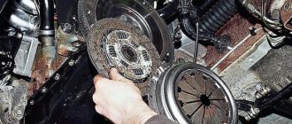
Self-diagnosis of the clutch disc
- Clutch not disengaging.
- Clutch slipping.
- The occurrence of vibration and extraneous sounds when the clutch is disengaged.
- The clutch pedal fails (does not return).
If the pedal does not return (falls through), the VAZ-2107 clutch cylinder may need to be replaced.
Replacing the clutch can be done in several ways. The first requires dismantling the power unit, the second requires removing the gearbox, which requires an inspection hole, a lift or an overpass. In the first case, it is necessary to use special equipment in the form of a lift. To remove the engine, you will also need to completely drain the coolant, disconnect the pipes from the radiator, and in the end you will spend a lot of time disassembling the parts. Therefore, it is advisable to use the second method, during which you can avoid all unnecessary operations. Let's look at how to replace a VAZ-2107 clutch step by step.
Removing the gearbox
After this, the starter is removed; as a rule, it is secured with three bolts. Before performing this task, you must disconnect the terminals from the battery. Finally, we dismantle the lever in the cabin, the cable on the speedometer and the brackets securing the exhaust pipe. After completing these operations, to dismantle the box itself, you need to unscrew the 4 bolts on the power unit casing.
Removing the disk
Installing the disc
We insert the new clutch disc in place of the old one. When installed correctly, the large protrusion should press against the release bearing. After making sure that the part is installed correctly, perform all the above operations in reverse order. You can use the gearbox input shaft as a guide. If you don’t have one, you can make one; it won’t take much of your time. The main rule is that the manufactured shaft can be easily pulled out by hand after installing the part. Finally, we screw the clutch basket, focusing on the previously made marks.
https://youtube.com/watch?v=rrO-5EmSUUo
Sources
- https://luxvaz.ru/vaz-2110/58-zamena-trosika-scepleniya.html
- https://remontavtovaz.ru/vaz-2110/zamena-i-regulirovka-trosa-scepleniya-vaz-2110.html
- https://vipwash.ru/stseplenie/zamena-stsepleniya-i-diska-na-vaz-2107
Simple step-by-step instructions for installing rear disc brakes
Step 1
We loosen the tension of the cables and bring the rear pads together, then use a 12mm wrench to unscrew the guide pins. Use a metal brush to clean the seat and carefully knock down the brake drum. I recommend using a rubber mallet to avoid damaging anything. Truly super tuning of a VAZ 2114 car requires patience and strength. Using a screwdriver, pry up the spring that tightens the pads and remove it. We pull out the spacer bar and take out the upper tension spring. After this, remove the brake pad, first lowering the handbrake lever.
Step 2
When all the old parts have been removed, you can begin installing the HCD. Decide how you want the caliper to be placed - behind or in front of the axle. The effectiveness of the brakes will not change in any way from this operation. I put the axles behind. This is more symmetrical and the weight of the brake mechanism will help with braking. Now you need to join the hub and faceplate into one piece. This operation should be taken seriously. It will be useful to watch a video on this issue, where domestic masters show their tuning of Russian cars in order to share their experience and show some of the intricacies of performing this work. The centering process must be carried out very carefully.
Step 3
Now you can straighten the corners of the beam before placing the hub combined with the faceplate on the beam. This must be done so that the corners do not interfere with the caliper. Personally, I flattened them with a hammer. This work can also be done using a grinder. You should not install a grinder under the left hub bolt, otherwise you will have to work with the grinder again and file the head of the bolt. The brake caliper bracket may rest against it.
Step 4
Well, now the most important thing. We install the bracket on the faceplate and put the brake disc on the hub. Place spacers at the connection points. This must be done at connection points. It happens that the size of the washers may differ, then you need to buy them for a specific car, in our case it is tuning a 14 model car. We tighten the faceplates and the connection of the brackets (I recommend doing this with a force of 3-4 N.M). We screw the hose to the caliper, install the pads, and you can close the tube sealing line. Now we seal the brake line. We check the line for leaks by pumping up the pressure with the pedal. If everything works as it should, then you can begin installing the HCD on the other side.
Source
Purpose of the timing belt
An internal combustion engine is a complex system that consists of hundreds of parts and several more or less independent mechanisms. And the engine will only function normally if its mechanisms, assemblies and systems work in harmony. This quality - consistency of operation - is of decisive importance for the engine. For example, a certain position of the pistons corresponds to a strictly defined position of the valves, and if this condition is not met, the engine simply will not work.
Therefore, in internal combustion engines there is an urgent task of synchronizing and coordinating the operation of several systems. In modern engines, this problem is solved using several drives - a gas distribution mechanism drive, a generator, a water pump, an ignition distributor, a fuel pump, etc. But the most important thing is the timing drive, which is necessarily present in all types of engines.
- 1,050 rub.
- 350 rub.
- RUB 3,785
- RUB 1,190
- 415 rub.
- 300 rub.
- RUB 2,070
- RUB 3,350
- RUB 1,135
The engines of VAZ passenger cars initially used a timing drive, implemented using a metal chain that connected the crankshaft gear to the timing shaft gear and some other units. However, later VAZ designers abandoned the use of a chain, preferring a simpler, more reliable and modern solution - a rubber timing belt.
The timing belt in VAZ engines solves several problems at once:
- Transmission of torque from the engine crankshaft to the shaft (or shafts, if there are two) of the gas distribution mechanism;
- Transmission of torque to auxiliary units, primarily to the water pump of the engine cooling system;
- Ensuring synchronous operation of the crankshaft and timing gear;
- Preventing mismatch between the operation of the crankshaft and timing gear in all engine operating modes.
It should be noted that in VAZ cars the timing belt serves to drive the camshafts and water pump. This belt could, in principle, rotate the generator and other mechanisms, but VAZ designers abandoned this idea. Why? Because in this case, a broken belt or jamming of any of the units would immediately disable the entire engine, so it is more reliable and safer to make a separate drive for some units. And a breakdown of the water pump will not stop the engine immediately, so combining the drive of this unit with the timing drive does not pose a potential danger.
VAZ cars use several types of timing belts, which differ in characteristics and design.
Cable replacement technology
To eliminate this category of breakdowns, there is a certain technique. The clutch is released using a cable. And its regulation is carried out mechanically in the engine compartment on a support in the upper part of the gearbox housing. When disengaging the clutch, problems may appear, which can be identified by checking the serviceability of the pedal mechanism, as well as pressing it five times all the way. Adjusting the operation of the unit determines the free movement of the lever by 1 cm in the opposite direction to the usual movement.
If this is not possible, then the cable needs to be replaced. When removing it, you should make a sharp movement to separate it from the attachment point, then, by squeezing the outer shell, achieve compression of the cable adjustment mechanism at the point of the rubber cuff. To fix the cable mechanism on the gearbox, it must be unfastened from the mounting unit.
Removing the glove box is quite a labor-intensive operation. It is necessary to remove the relay panel (without detaching the wires from the terminals), the clutch pedal housing, only then unfasten the cable and pull it out of the car
Next, carefully pull it through the rubber bushing. Installation is performed in reverse order
Installation of the roller at the end of the cable is carried out by securing the outer parts of the cable to the gearbox, followed by rigid fixation
Installation is performed in reverse order. Installation of the roller at the end of the cable is carried out by securing the outer parts of the cable to the gearbox, followed by rigid fixation
It is important to stretch the cable sheath in the direction of travel and place a rubber damper in the clutch lever. If, during the process of replacing the clutch cable of a VAZ 2110, it is not possible to pull the sheath through in the recommended way, then it must be pushed through until it is possible to compress the plug at the point where the rubber cuff is located
If the sheaths are misaligned, the cable adjustment mechanics should be started again. Then place the casing and relay panel on the mounting conductor and recheck the mounting terminals in detail.
Depressing the clutch pedal and then checking the cable adjustment mechanism completes the installation. After all the preliminary manipulations, you can reconnect the battery.
There are times when the VAZ 2110 clutch cable has been replaced, but the vehicle is still impossible to operate. Probably the reason lies in a poor-quality cable mechanism. If it is in good working order, ensuring further operation consists of repeated repair operations. Duplicating previous actions will eliminate the possibility of an error and will also allow you to check the complex operation of the entire mechanism. If the attempt fails again, the cable must be replaced completely.
When replacing the VAZ 2110 clutch cable, it is important to know this key point: if the vehicle was produced in a pilot production batch, then the bracket can be fixed in the form of a bolted connection using a Phillips screwdriver. In this case, a traditional screwdriver will not cope with the problem of unscrewing, and a shortened version of the tool will be required. However, in the event of a sudden breakdown on the route, the fasteners can be released using a long screwdriver through the safety block
After completing the repair, for subsequent ease of maintenance, it is recommended to replace the old bolt with a standardized version with a wrench head
However, in the event of a sudden breakdown on the route, the fasteners can be released using a long screwdriver through the safety block. After completing the repair, for subsequent ease of maintenance, it is recommended to replace the old bolt with a standardized version with a wrench head.
Replacing and installing a cable requires mandatory adjustment of the pedal travel from top to floor in the range from 12.5...13.0 cm. That is, the pedal must be placed at the same height as the others. Adjustment is carried out by loosening the nuts on the fastening holder located on the gearbox.
By changing the location of the tip using the nuts, you can control the amount of stroke. When a satisfactory result is obtained, tighten the nuts. At this stage, installation and adjustment of the clutch cable is complete.
Important points when replacing the cable
Unscrewing the fastener
- As practice shows, the procedure for replacing a cable on a “ten” begins in the engine compartment. You are required to hold the fork and at the same time pull the cable that is removed from the fork.
- Then the cable fastener is removed from the bracket, which is located on the gearbox. Having completed this procedure, we go into the interior and dismantle the damaged element, that is, the cable.
- The result of the repair is influenced not only by the quality of the new cable, but also by the correctness of the entire replacement procedure.
- If you are dealing with a “ten” from an experimental industrial batch, then the bracket will be presented as a bolt with a Phillips-head screwdriver. To dismantle such a fastening element, you cannot use a regular screwdriver. A special shortened tool will be required.
- If the cable breaks while driving, you can unscrew the bracket with a handy tool, but through the safety block.
- It is strongly recommended to replace the non-standard bolt with a regular one, which can be unscrewed with a simple wrench.
- Be sure to keep a set of tools in your car, since it is extremely rare for a cable to break at the right moment. There is hardly a right moment for any kind of machine breakdown.
Malfunctions
Any driver experiences an unpleasant feeling when the clutch pedal sinks to the floor. This can happen if the clutch cable breaks; it is also possible that the release fork breaks (this case is discussed in another article). The cable breaks more often on older cars that are used in extreme conditions or all year round.
The cable may become frayed, which affects the smoothness of the pedal and the operation of the clutch. This cable also requires replacement.
If the clutch cable is broken, you can drive your car to the repair site. You need to start the car in first gear and shift while driving. The following situation is possible: the cable broke while the gear was engaged, and the car stalled.
There is a possibility that it will be difficult to engage the neutral position. Then your car won’t even be able to roll off the roadway. The transmission is disengaged by rocking the car forward and backward and disengaging the transmission at the same time. You can jack up one of the wheels and spin it by hand, this will also help.
Even if the cable is not replaced, gear shifting is possible. It is possible to get to the service station, but such driving has a negative impact on the service life of the gearbox.
The cost of the spare part is low, about 300 rubles. The cost of replacing a cable in a car service is 400 rubles.