As you know, a car generator is designed to provide power to all electrical equipment in the car when the engine is running. This unit in domestic “tens” consists of many elements that ensure its optimal operation. One such device is a diode bridge. What functions does it perform, what do you need to know about its malfunctions, and how is the diode bridge of the VAZ 2110 generator replaced? You can find answers to these and other questions below.
Description of the diode bridge on the “Ten”
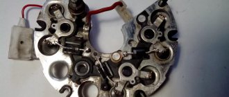
How is the diode modified and installed in the device? For what reasons can a bridge fail? To begin with, we suggest that you familiarize yourself with the description of the part. If you dismantle the generator assembly from the car and remove the cover, you will be able to see the diode bridge (DM), which is located immediately behind it.
Purpose and functions
What functions does the DM perform:
- The primary task of the device is to convert alternating current into direct current.
- The DM also performs the function of blocking current from entering the stator winding. In this case, the device actually performs the one-way valve option.
- In addition, the DM is designed to increase the safety margin of the generator unit. It allows you to protect the mechanism from the effects of adverse factors and contamination on the device, and this, in turn, can negatively affect the functionality of the mechanism as a whole.
Device
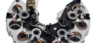
As for the device, in the factory configuration the DM for the “tenth” generator is a monolithic structure. This design, as a rule, is quite strong and reliable, is characterized by its small size, as well as a relatively low price. The only drawback characteristic of factory-made DMs is that if one of the diode elements burns out, local replacement of the damage will not be possible. That is, the car owner will have to completely change the factory axle with his own hands.
As for the design features itself, the DM consists of:
- two aluminum plates;
- spacers made of plastic;
- as well as nine diodes, which are connected to each other by soldering into one structure, that is, a bridge.
Manufacturing and installation of a diode in a VAZ-2114 generator
Now that everything is ready, we install an additional diode, more powerful than the previous one. You will need half a meter of wire 2*0.75mm. We solder the ends to the female and male terminals No. 4. We dress them in cambric, or better yet, in heat shrink. By the way, the old one must be removed from the system. Let's take action:
- Now, solder the following circuit to the diode: mother to the cathode, folder to the anode.
- We insulate the diode. For example, we take a film container.
- We remove the “minus terminal” from the battery.
- We unscrew the “+” wires from the generator, disconnect the “D” wire to the tidy.
- Remove the generator cover.
- Through the slots in the cover, we connect the “mother” to the LV, the “father” to the standard wire.
- We carry out the assembly.
Now, everything is ready for the final check and measurements.
Possible malfunctions: signs and causes
As stated above, the purpose of diode elements is to convert alternating voltage to direct voltage. If one of the diode elements fails, then its malfunction may be indicated by such a sign as a decrease in the voltage level, as well as power in the vehicle electrical network.
For what reasons may problems occur in the operation of the DM:
- Manufacturing defects. As practice shows, many modern DM manufacturers use aluminum shells of fairly low quality in their production. Accordingly, this affects their reliability as a whole. That is why it is recommended to use DM equipped with steel shells, since this directly affects the service life.
- Moisture gets inside the device. Regular exposure to moisture can cause oxidation, in particular, on the surface between the device body and diode elements.
- Engine fluid getting into the unit is one of the most common causes. Exposure to lubricant can lead to disruption of the functionality of the device as a whole, especially if it gets inside the generator unit, directly on the DM.
- Another reason why DMs on “tens” often fail is the polarity of the battery is reversed. If you connect the battery to a charger or accidentally reverse the polarity while “lighting up” the car, this will most likely cause the motor to burn out. Therefore, you should always remember that plus is connected to plus, and minus is connected to minus.
- Regular operation of a vehicle with a weak battery. If the battery does not pull the load and constantly operates under conditions of reduced charge, then the reason may be the inoperability of the DM.
Battery voltage problems in winter
How to increase the charging of the generator on a VAZ 2114 in the winter? This is another problem that concerns the cold season. The fact is that in winter the battery may not have time to warm up. As a result, it constantly discharges.
To prevent such a situation, you should warm it up to at least 0 degrees Celsius. In order to warm up the battery to the desired temperature, you should wait at least 20 minutes. At this time, you need to drive, and don’t stand in traffic jams, otherwise it won’t be of any use.
Diagnostics
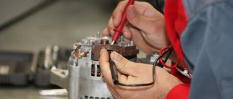
The diagnostic procedure must be carried out on a dismantled generator device, so the unit must first be removed. When the mechanism is dismantled, the plastic cover is removed from it, as mentioned above, the DM is located immediately behind it (the author of the video about self-diagnosis with a multimeter is Ramil Abdullin).
For diagnostics you will need a tester - a multimeter - the test is carried out as follows:
- First, the multimeter should be activated in ohmmeter mode. Having done this, the positive probe of the tester must be connected to the diode bus.
- In the same way, connect the negative probe of the tester to the corresponding contact on the diode bridge.
- Next, you need to monitor the tester readings. If the diode bridge is in working condition, then the tester display will show values close to infinity. If there are no such values, then most likely the DM is inoperative and should be replaced. But the diagnosis does not end there.
- Next, you will need to swap the location of the probes, that is, the negative contact is connected to the positive one and vice versa. Having done this, again look at the multimeter reading on the display. If there are no failures in the operation of the DM and the device as a whole is functioning normally, then a value of several hundred Ohms should appear on the tester screen.
- If the DM is equipped with an additional diode, then you can check it too. In this case, the diagnostic procedure is performed in a similar way; you just need to repeat all the steps.
Photo gallery “Self performance test”
DIY replacement instructions
In the event of a breakdown, the repair of the DM consists of its replacement, which is done as follows:
- First you need to turn off the ignition, open the hood and turn off the power to the on-board network; to do this, disconnect the battery.
- Once the battery terminal is reset, you will need to disconnect the pink cable responsible for activating the generator assembly. The wire itself is fixed with a bolt and nut; the nut itself will need to be unscrewed.
- Now you need to slightly loosen the tension on the top as well as the bottom nuts. Unscrew the tension screws and remove the strap. Inspect it - if the belt shows signs of damage - cracks, delamination - then it is better to change it immediately. If the strap is intact, set it aside.
- After completing these steps, you need to rotate the generator mechanism 90 degrees, this is done so that you can access the lower mounting screw. Unscrew it.
- Next, carefully inspect the body of the dismantled unit. If necessary, clean - there should be no dirt, especially on the connections. Dirt getting inside the generator housing can also lead to its incorrect operation and even failure. Bend the fasteners and remove the cover.
- Next, you need to clean the inside of the rings as carefully, but most effectively as possible.
- After this, all you have to do is dismantle the failed DM and replace it with a working part. When the installation is completed, the structure is assembled in the reverse order. Do not forget to tighten the strap, just make sure that it is not too tight, this is important. Having done this, you will need to start the engine of your car and diagnose the operation of the new DM.
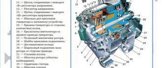
Generator design: its composition
ATTENTION! A completely simple way to reduce fuel consumption has been found! Don't believe me? An auto mechanic with 15 years of experience also didn’t believe it until he tried it. And now he saves 35,000 rubles a year on gasoline! Read more"
The mere fact that a gene is always under high load a priori includes it in the risk group. He needs an eye and an eye. Experienced and caring motorists know this. Beginners and amateurs don’t pay attention, “ruin” the new device and battery, and then wonder why the car doesn’t drive.
What does a gene consist of? Its components necessarily include a rotor or inductor. Its main function is to create a magnetic field inside the device. The rotor has a shaft on which there is an excitation winding. Due to it, the gene is recharged or self-excited.
Video “How to avoid mistakes when replacing the DM in a VAZ 2110”
More clear instructions for replacing the diode bridge in the “Ten” with a description of the main points and nuances are given in the video below (the author of the video is Semyon Pedan).
Let's start with the fact that a diode bridge is an electrical circuit, a chain of diodes designed to convert alternating current into direct current. A faulty diode bridge is one of the main causes of generator malfunction, and is also a powerful consumer that can drain the battery to zero overnight.
A faulty diode bridge can both discharge and recharge the battery, which can result in major electrical problems. The principle of diodes, in addition to converting current from alternating to direct, is the unipolarity of current transmission from the generator to the battery. In other words, a working diode transmits current only in one direction (generator - battery), a faulty diode transmits current in both directions (battery - generator) or does not transmit anything at all. Diodes burn out due to poor contacts or moisture.
Before you start blaming the diode bridge for all your problems, be sure to check the generator brushes and voltage regulator.
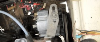
To start checking the diode bridge, you need to remove it, fortunately the process is simple. You can also do without removing the rectifier block (diode bridge), but this is very, very inconvenient.
One way to check the diode bridge is to check the on-board system for current leakage (How to check for current leakage?)! If the current consumption in a stopped engine with electrical appliances turned off is 1A per hour or higher, then most likely the problem lies in the diode bridge. The bridge can only be checked more thoroughly when removed.
Electrical diagrams and indicators
To increase the voltage even more, at least to 14 volts, it is necessary to install a diode in circuit D, the voltage regulator. Any diode with a breakdown voltage of 20V and a current of at least 5A is suitable. The voltage drop is preferably no more than 0.6-0.7V. The 2D219B diode is excellent.
| 2D219A | 15 | 10 | 0.6(10A) | 20 (15V) | KD-11 |
| 2D219B | 20 | 10 | 0.6(10A) | 20 (20V) | KD-11 |
| 2D219V | 15 | 10 | 0.45(10A) | 20 (15V) | KD-11 |
| 2D219G | 20 | 10 | 0.45(10A) | 20 (20V) | KD-11 |
Let's look at the circuit diagrams of diodes:
How to remove the generator diode bridge (rectifier unit)?
- We remove the negative terminal of the battery and disconnect/unscrew the wires going to the plastic casing of the generator.
- Disconnect the wire block “D”.
- Remove the protective rubber cap from the tips of the “+” terminal wires. We unscrew the nut securing these wires and remove them from the generator block.
- Next, remove the black plastic casing of the generator itself. To do this, you need to disconnect the three spring clips located around the perimeter of the block.
- We find the voltage regulator, and use a Phillips screwdriver to unscrew its fastenings.
- We take out the voltage regulator assembly with brushes.
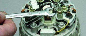
- Take the key to “8” and unscrew the 3 bolts securing the bridge.
- We bend the leads to the stator winding to the side and use a Phillips screwdriver to unscrew the capacitor mount.
Technical characteristics of the generator 9402.3701
| Maximum output current (at 13 V and 6000 min-1), A | 80 |
| Voltage, V | 13,2–14,7 |
| Direction of rotation (drive side) | right |
The stator and generator covers are secured with four screws. The rotor shaft rotates in bearings installed in the covers. The lubricant placed in the bearings at the factory is designed to last the entire service life of the generator. The rear bearing of the generator 9402.3701 is pressed onto the rotor shaft and is pressed by the rear cover through a plastic sleeve, the front bearing is pressed and rolled into the front cover and can only be replaced together with it. Its inner race, together with the thrust ring and washer, is clamped by a nut between the pulley and the step on the rotor shaft. The front bearing of the generator 37.3701 is secured with four screws between the inner and outer washers and can be replaced separately from the front cover. The rear part of the generator 9402.3701 is closed with a plastic casing with latches.
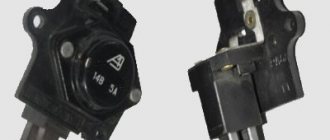
The generator stator contains a three-phase winding made in a star configuration (the terminals of the phase windings have a common point). The second ends of the phase windings are connected to a rectifier bridge consisting of six silicon diodes (valves) - three “positive” and three “negative”. The valves are pressed into two horseshoe-shaped aluminum holder plates in accordance with the polarity (positive and negative - on different plates); one of the plates also contains three additional diodes, through which the excitation winding of the generator is powered after starting the engine. The plates are combined into a rectifier unit mounted on the rear cover of the generator (under the plastic casing of the generator 9402.3701).
The excitation winding is located on the generator rotor, its leads are soldered to two copper slip rings on the rotor shaft.
Power is supplied to the field winding through two brushes. Alternator slip rings (9402.3701) have a reduced diameter to reduce peripheral speed and reduce brush wear. The brush holder is structurally combined with the voltage regulator and is mounted on the back cover of the generator. The voltage regulator is non-separable; if it fails, it is replaced.
Until 1996, for the 37.3701 generator, the brush holder and voltage regulator were separate units (voltage from terminal “30” of the generator was supplied to terminal “B” of the voltage regulator). Now voltage is supplied only to terminal “B” (terminal “B” is missing). According to their characteristics, the new and old voltage regulators are the same and, when assembled with a brush holder, are interchangeable.
To protect the on-board network from voltage surges during operation of the ignition system and reduce interference with radio reception, a capacitor with a capacity of 2.2 ±0.04 μF is connected between the terminals of the “positive” and “negative” valves (between the “+” and “ground” of the generator), located on generator rectifier block 9402.3701 and generator rear cover 37.3701.
When the ignition is turned on, voltage is supplied to the excitation winding of the generator (terminal “D” of generator 9402.3701 and “B” of generator 37.3701) through a control lamp in the instrument cluster (the lamp is lit) and resistors connected in parallel to it. After starting the engine, the excitation winding is powered by additional diodes of the rectifier unit (the control lamp goes out). If the lamp lights up after starting the engine, this indicates a malfunction of the generator or its circuits.
The “minus” of the battery should always be connected to the “ground” of the car, and the “plus” to the “B+” terminal of the generator 9402.3701 (“30” of the generator 37.3701). Switching back on will lead to breakdown of the generator valves.
It is not recommended to disconnect the battery when the generator is running (especially on engines equipped with an injection system). The resulting voltage surges in the on-board network can damage the electronic components of the circuit.
The generator valves (and other devices in the vehicle’s on-board network when the generator is connected) should be checked at a voltage no higher than 15 V; a higher voltage (for example, when checking with a megger) can cause damage to the valves.
If it is necessary to check the insulation of windings with high voltage, the generator should be removed, and the winding terminals should be disconnected from the rectifier unit and voltage regulator
How to install a diode bridge (rectifier unit)?
The diode bridge is installed in strictly reverse order.
Background:
My 140 amp generator started howling in an inhuman voice a long time ago, I removed it and sent it for diagnostics. The diode bridge was ordered to be replaced. As a result, the generator was put aside in the nightstand. My old 80-amp generator recently broke down, and I even took the battery with me... In general, I decided to repair the diode bridge on my own, since a new one costs more than 10 thousand rubles, and the auto electrician didn’t know where to buy 50-amp diodes.
You can’t find diodes in Automotive stores; they are rated at a maximum of 30-35 amps, but my task was to find diodes rated at 50 amps. As a result, after surfing the CARGO online catalog, I found the ones I needed. I'm publishing the numbers.
Diode Cargo 50A - 138634 - 6 pcs. Diode Cargo 50A - 138635 - 6 pcs.
For a 140 ampere generator you need 12 diodes - 6+6, for an 80 ampere generator only 6 - 3+3.
We also need a tool, a soldering iron of at least 50 watts with all the accessories. Dye. I chose heat-resistant silicone. I applied it with a brush, so the layer is thicker. Well, not very smelly hands))
Main stages:
— We dismantle the diode bridge — We remove the old diodes — We halve the diode bridge — We install the diodes (carefully hammer them into the case through a wooden spacer) — We assemble the bridge, solder the contacts — We paint carefully in several layers — We put the bridge in place
On one half of the bridge there are diodes of one type, on the other half - of a different type (different polarity). Having the most ordinary multimeter it will not be difficult to understand where each one is located.
Final voltage measurements and results
After the installation was completed and the entire electrical circuit was working, voltage measurements were made at idle speed of the running engine. The results surpassed themselves; the voltage in the entire electrical circuit increased.
Let's consider a table of the results of the measurements obtained:
| Load | Voltage up to | Voltage after |
| without load | 14.2 | 14.45 |
| +dimensions | 13.8 | 14.45 |
| +PTF | 13.7 | 14.4 |
| +neighbor | 13.6 | 14.35 |
| +heater | 13.5 | 14.3 |
| +Fan | 13.4 | 14.2 |
| +far | 13.2 | 14.1 |
| + heating | 13.1 | 14.0 |
| +heater max | 12.9 | 13.95 |