Installation of alarm system on Lada Kalina
Nowadays, any car owner tries to protect his property by installing alarms of different types and levels. Therefore, now we will tell you how to install an alarm system on a Lada Kalina with your own hands.
First, you need to disassemble the control column and remove the dashboard in order to get to the wires that suit us; I will attach a photo below.
We take an 18-pin connector, we don’t need as many wires there as there are.
1) 2 wires for turn signals 2) Trunk limit switch 3) Hood limit switch 4) Door limit switches (there will be a separate story about them because everything is very neglected there) 5) Plus 6) Accordingly, minus. 7) Handbrake and generator.
Closely
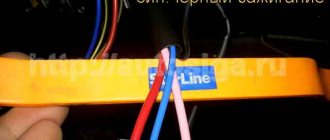
we read the annotation and take 2 wires that should go to the turn signals, and look into the wiring harness that goes straight to the tidy. There we look for blue and blue/dark and connect 2 wires from the alarm to them.
There, I mean in the same harness, the handbrake is connected, it is needed for autostart, minor theories: by lowering the handbrake the car stalls if there are no keys in the ignition, stopping the car and putting the handbrake on the car will not immediately stall, preparation for autostart, because just to turn it off, you first need to turn the key, turning off the ignition, then lift the handbrake, but later you won’t be able to start from autostart.
So. Let's continue with the handbrake. We find the brown/blue wire and connect the handbrake to it. It's simple.
The next step is to control the operation of the motor, I did it on the generator, in other words, when the machine starts up, voltage appears there, which indicates a successful start. We find the brown/white wire and connect to it. Everything needs to be soldered and perfectly insulated.
At this step, we leave the tidy space and go down to the threshold of the driver's door and to the BUS (glass unit control unit), it is located under the rear seat on the left.
We only need 2 wires in the threshold. Unlocking and locking doors. The minus of this system must be connected to a bolt in the body.
We find the pink/dark wire - it is responsible for unlocking the doors, connect to it with a suitable wire.
Next is pink/snow-white - locking the doors.
Be careful not to confuse it with reddish/black because they are very similar, for example, as I had, there was a slight lack of light and please, the wrong wire.
Here you can also take the hood switch, the snow-white/dark wire, but I didn’t take it, but took it under the rear seat, i.e. in BUS.
We have come to the same BUS and here we have a little more work to do, and specifically, let's start with the usual one, connect the trunk and hood end switch, both wires are snow-white/dark. How to distinguish them? The one that is responsible for the trunk is located on the very right edge if you look at the BUS so that the wires go straight to you. Let's connect to it. The hood wire comes out slightly to the left, but the main thing you just need to know is that for the trunk it is from the very edge, and then you can’t go wrong.
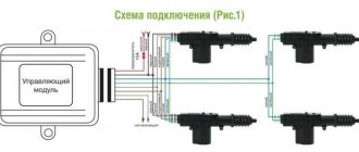
This is where the fun begins, to connect the door limit switches in such a way that you can relax the doors and arm them without waiting for the lamp to go out, then you need 3 diodes with a resistance of 1 Ohm, these are 1N4007, if my memory serves me correctly, I didn’t find them and for now I did it differently, if you have diodes, read on. If not, below I will explain how to create it differently.
There is one wire from the signaling to the door limit switches, and there are 3 of them in the BUS, for the front right, front left and rear. We take the wire from the signaling and branch it into 3 by soldering 3 small wires to it, a diode is soldered to the ends of these wires and then these wires go to the end switch of the front right door, it has a brown/reddish color.
To the end of the front left door there is snow-white/blue and for the rear there is snow-white/reddish. The diagram of this connection is below.
Do-it-yourself car alarm installation in a garage
Do-it-yourself alarm installation: main points
Our country is not one of the countries where car alarms are an optional element of equipment. This is often required by insurance companies. But even in prosperous countries, some automakers install security devices on their models as standard. As a rule, these are expensive models on which the “alarm” is a multi-level system for protecting cars from theft. In other cases, car owners have to take safety measures on their own.
It is often practiced to install a car alarm with your own hands, because this is not such a difficult task. But, it should be noted, it is painstaking. In this article we will talk about installing a budget set of security equipment, because it is inexpensive but effective “alarms” that are in greatest demand.
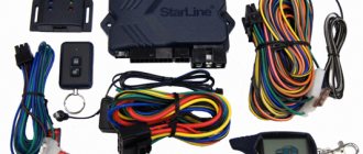
The alarm kit includes:
- User guide;
- Instructions on how to install an alarm system on a car, with a description of the equipment;
- Central control unit (CU);
- Set of wires for control unit with clip connectors;
- Emergency alarm stop button;
- Starter interlock relay with wires;
- Indicator lamp with wire;
- Shock sensor with sensitivity adjustment;
- End wire for hood or trunk;
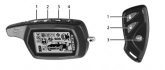
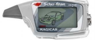
- Control panels (key fobs);
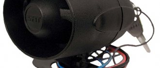
- Sound siren.
Depending on the price of the device, the kit may not include one or another element that can be purchased separately. The same applies to central locking mechanisms.
Installation of a “signal”!
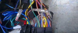
First, you should study the connection diagram and lay out the elements of the security system on the table in your garage. The main element of the signaling is the control unit, and a chain of connections should be built around it. You will also need a battery. Typically, for ease of installation, connection clips are uniquely configured to avoid incorrect connections. The shock sensor, emergency alarm shutdown button and lamp indicator are connected to the control unit with their own connections.
For other connections, a wiring harness comes out of the control unit. This is what “scares” inexperienced installers. But you shouldn’t be scared: the wires in the main harness coming from the control unit are different in color, and the purpose of each wire is described in the instructions.
The harness contains wires for the siren, starter relay, direction indicators, central locking drives, and power window drives. In order not to forget which wire is responsible for what, they are marked with tape with the inscription. Once you have made sure that the system on the table works from the remote control, you can begin installing the alarm system in the car.
Alarm installation - main points
Before installing the alarm, you will have to remove the dashboard and door cards. Follow these guidelines:
- When installing, avoid twists and unreliable connections - use terminal blocks;
- Hide the wires under the casing; find an unusual, hard-to-reach place for the control unit and the emergency button to turn off the alarm;
- It is better to start the installation from the control unit, and then connect element by element sequentially;
- When connecting to the on-board power supply, pay attention to the polarity;
- Collect the excess length of wire into a bundle;
- Fasten the mass securely.
As you can see, in order to independently install an alarm system on a car, it is enough to have basic knowledge and skills in the field of electricity. The main thing is not to rush.
Source: https://vaz-remont.ru/ustanovka-avtosignalizacii-svoimi-rukami-v-usloviyax-garazha/
We combine the alarm with Kalina central locking
When installing an alarm system, they most often make mistakes with connecting the central locking system. Standard central locking is currently installed on almost all cars, and the “1st generation” Lada Kalina is no exception. But the fact is that in the “Norma” configuration one scheme for connecting locks is used, and in the “Lux” this scheme is different. And the signal connection, obviously, is also done differently. Let's look at how the alarm system and the alarm system can be combined, if we are talking about any of the designated configurations.
Substitutes
| vendor code | Price, rub.) | vendor code | Price, rub.) |
| Lightweight brake drum made of cast iron Pilenga 6224 | from 1600 | Fenox TO2108O3 | from 1700 |
| LPR 7D0271 (diameter 200 mm, height 50 mm.) | from 1800 | TRW DB4307 | —/— |
| Brembo 14707910 | —/— | Bosch 0986477146 | —/— |
| ATE 24.0220-0020.1 | —/— | BREMBO 14.7079.10 | —/— |
| TRW DB4171 | —/— | TRW DB4187 | —/— |
Two configurations and two schemes
In the “Norma” version, if it has a central locking system, you can use two control wires. Ground is supplied to one of them if it is necessary to open the locks, and to the second one - if it is necessary to close them. The period of connection to ground should take 0.7 seconds, and most alarms have such a setting.
If we talk about the “Lux” configuration, then the control wires will not help us. The relay contacts integrated into the alarm will have to be connected to the breaks in the power cords. Despite all the complexity, there were no complaints about this scheme, and we will look at it right now.
The “luxury” option is the most difficult
First, you need to make sure that the central locking system in the frame is really connected according to the “Lux” scheme. The control key located on the door must be a trigger (non-latching). If you have this particular version of the car, you will have to tinker. It will be necessary to extend 4 power cables to the signaling unit. These cords, in turn, must go from the break point of the two standard wires (yellow-white and yellow-black). Find them in the bundle under the threshold.
It doesn’t matter what kind of alarm system is supplied with 2 relays, one of which is triggered for closing, the second – for unlocking the locks. Power cables drawn from the break points are connected to the relay contacts.
The part of the yellow-white wire that goes to the actuators is connected to the common contact. Another relay contact (normally closed) is connected to the 2nd half of the cable. A similar method is used to connect to the yellow-black wire, but here an opening relay is used, not a locking one. Any of the normally open contacts receives power.
All power wiring is supplied with power through a fuse.
In our case, the rating “15 Amperes” is used. Specifically, before installation, it is necessary to call the pair of wires that are oriented to the actuators. The probe should show a value of 1.2 - 1.3 Ohms. And of course, when performing installation work, you first need to remove the negative terminal from the battery. Be careful!
Substitutes
| vendor code | Price, rub.) | vendor code | Price, rub.) |
| ABS 17342 | from 1300 | METELLI 23-0411 | from 1350 |
| BOSCH 0 986 479 346 | —/— | LPR L1052V | from 1400 |
| BREMBO 09.8903.14 | from 1500 | TRW DF4107 | —/— |
| FERODO DDF1147 | —/— | BREMBO 09.8903.75 | —/— |
| VAZ (R13) ventilated LUCAS DF4108 | —/— | TRW 2110-3501070 | —/— |
| 2110-3501070/71 | —/— | —/— |
Tips for both cases
Before all this, we note that when connecting the relay to the power wiring, you cannot create a very long control pulse. Setting the value for more than a second can burn the actuators. Here we were talking about programming, but now let's talk about the electronic part. As is clear, before installation it is necessary to open the hood and disconnect the negative terminal.
It is not permissible to abuse this advice in any case.
As for installation, it will be better if the power wire taps are carried out by an auto electrician. With signal wiring, everything is simpler, but the rules will be similar in any case:
- It is not allowed for the cord to touch the insulation of iron parts. If the contact has space, use additional protection. For example, a heat-resistant tube placed over electrical tape is suitable;
- It is better to connect any power cables using twisting. Each twist space is painstakingly insulated.
- The cross-section of wires carrying significant current must be sufficient so that the conductor does not heat up. This is how you can protect yourself from unexpected consequences.
The last tip concerns power wiring. And the ability to create a twist is an entire art.
It is impossible to learn this art in one day.
When connecting any equipment, you should strive to include as few configurations as possible in the standard wiring.
There must remain the opportunity to create what follows: to return everything as it was. From time to time it happens that one or more characteristics of the signaling does not accept the value that is appropriate for the car. Then the alarm system is changed or its use is abandoned altogether. This must be taken into account.
Main features
Some advantages of purchasing this vehicle include:
- Relatively low price.
- Practicality when used for domestic purposes.
- Inexpensive maintenance.
- Inexpensive repairs, as well as an unlimited number of spare and inexpensive parts.
Connecting the Lada Kalina alarm system
- 44803 views
Alarm installation diagram for Lada Kalina 2 from 2013, complete with manual transmission
We install an alarm system with auto start Starline A93 eco with a shock and tilt sensor
We disassemble the Lada Kalina interior
Remove the driver's door sill trim; to do this, you need to unscrew the 5 mounting screws.
To access the ignition switch connector, remove the control case. To do this, you first need to remove the torpedo (fastening with latches), then unscrew the two bolts and 5 screws securing the lower part of the control casing and remove it.
Remove the device panel. To do this, you first need to remove the decorative trim of the dashboard to the left of the control column (fastening with latches), then unscrew the three screws securing the decorative trim of the device panel, unscrew the four screws securing the device panel and pull it out, disconnecting the connector.
To access the central locking connection, you need to remove the inner trim of the driver's door, to do this, remove the decorative plug, unscrew the bolt and three fastening screws and remove the trim (fastening with snaps).
Install a siren under the hood (fix it with screws), an engine temperature sensor (using plastic ties) and an additional limit switch. Connect the hood switch to the orange-gray wire of the X4 Starline connector according to Diagram 1 on page 8. Route the wires to the passenger compartment through the standard seal on the left side of the engine shield.
Lada Kalina connection points
Starline mass connection to the right of the control shaft (secure with an M6 nut).
Connecting the Starline parking brake in the device panel connector harness according to Scheme 2.
Connecting the light signal control circuits in the device panel connector harness.
Connection of the driver's door limit switch in the left threshold harness. For the other three doors, install additional limit switches and connect to the blue-black wire of the X4 Starline connector according to Diagram 3.
Connecting the trunk limit switch in the lampshade connector harness.
Connecting the engine operation control in the connector harness of the electric power steering control unit.
Connecting the central locking control in the driver's door wiring harness.
In the ignition switch connector harness, connect the power circuits for starting the engine, power supply for Starline and the autostart power module. It is recommended to make these connections by soldering.
Did you like the material? We would appreciate your rating and comment.
Source: www.info-myauto.ru
Standard alarm remote control unit: dismantling and location
11.10.2013
A couple of days ago, I received an email from a blog reader with a question about the remote control unit for the security alarm. I decided to write a short article to show where this module is located and how to remove it if replaced with a new one.
Where is the remote control unit for the security alarm on Kalina
This part is located under the rear seat, more precisely under the left half. In order to get to it, you must first raise the seat by pulling the cord:
And under the floor covering there is a part that interests us; in the photo below the approximate location is shown by an arrow:
Now below we will analyze in more detail the entire procedure, starting from removing the casing and ending with dismantling the module itself.
Removing and installing the standard alarm remote control unit on Kalina
Disconnect the negative terminal from your vehicle's battery.
To perform this repair, you will need a minimum of equipment and tools. The list of what you need is given below:
- crosshead screwdriver
- Head for 10
- Driver or ratchet
- Extension
So, first you need to unscrew the 4 bolts securing the plastic sill trim:
After this, freely remove this decorative trim:
Now you can start removing the floor covering, but there is no need to remove it completely. Simply lift it halfway to gain access to the alarm unit.
Now that you can remove it, you must first disconnect the plug with the wires. To do this, on the left side you need to press the plastic lock of the plug and pull it to the side:
In the end, this is the final result:
Now all that remains is to unscrew the two nuts securing the alarm unit itself through the holes, as shown in the photo below:
And the final step in this repair will be to remove the module from its seat:
If replacement is necessary, install this part in the reverse order of removal. This work is completed within 10 minutes and is not difficult.
Standard alarm remote control unit: dismantling and location Link to main publication
Source: https://ladakalinablog.ru/blok-distancionnogo-upravleniya-shtatnoj-signalizaciej-demontazh-i-mestopolozhenie/