Having learned the prices for central locks, I thought, is it worth buying? Maybe there is an easier way out of this situation. And I went online: I came across this diagram
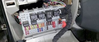
For the circuit to work, you only need 2 five-contact relays, one five-wire activator (solinoid, or drive as you like :)) and 3 two-wire ones. A 5-pin relay works in the same way as a regular 4-pin relay, its peculiarity is that the central contact 87a is normally closed with contact 87, due to this the system that is used in power window buttons is repeated. As a result, when the main lock is activated, everything is activated, be it from the key or alarm :) But there is a small problem. They operate with some delay and to re-open or close you need to wait 20 seconds, but this time is selected by selecting resistors. I’ll find the official article and indicate the link :) I haven’t checked the operation of the circuit myself yet
For ease of use of vehicles, car manufacturers have long used central locking, which is a subsystem of a larger “comfort” system and is often combined with an alarm system. Central locking – locks one or all car doors. In addition, it is responsible for unlocking the fuel tank flap and trunk. If the car model is old, then the system can be installed additionally. Has remote control (RC).
How it works
The car central locking system includes:
- Input sensor: limit switches and microswitches.
- Block – central locking control.
- Actuators.
Input sensors include:
- Door limit switches – are responsible for the location of car doors, transmitting a signal to the power supply.
- Microswitches are responsible for the structural elements of the locking device.
- Two microswitches fix the cam mechanism of the front doors: one is responsible for the “lock” signal, and the other is “unlock”.
- Two more are responsible for the central locking.
- Microswitch for the lever mechanism of the lock drive.
Such a device involves transmitting a signal from microswitches first to the control unit, then to the power circuit, through which the signal goes to the doors (actuators), trunk lid and fuel tank flap. Result: the locks open.
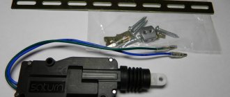
An actuator is an actuator that causes the lock to operate.
The system operates remotely (remote control): There is a special remote control button on the ignition key, the signal is transmitted to the antenna, and from it to the unit. The range of the remote control is 10 meters. You can connect to an alarm system.
Operating principle of central locking
The central locking system, as a rule, comes from the remote control. For this purpose, a special sensor was specially built into the lock handle, and a receiving antenna was built into the main block. You can drive the car from a distance of up to 10 m.
To activate, press a button on the remote control, the signal is transmitted to the antenna and the doors are locked. At the same time, the alarm immediately comes into readiness.
- Google+
- LJ
- Blogger
In the event of an emergency, locked doors open automatically.
During locking, microswitches are activated via the remote control or by turning the key. What happens next is:
- The central locking wiring diagram analyzes the received pulses.
- The communicator sends signals to the main and other units.
- The actuators receive a signal to block. All locks close automatically.
- Google+
- LJ
- Blogger
Control block
The block is responsible for the operation of the lock. The control circuit includes digital elements - they transmit a signal to the rest of the system components.
This device of the car central locking system interacts with the alarm system and can also be controlled by a remote control. You can install it yourself, but most modern cars already have central locking with remote control.
The remote control operates from a separate electronic unit, which is connected to the system and controls it.
TYPE A. Positive Control
This type of control is characterized by the positive polarity of control pulses. In Fig. 2 and 4 show diagrams for a car in which a central locking controller is already installed by the manufacturer, and pairing with the car alarm is carried out through relays built into it. In Fig. Figure 3 shows an option for pairing with a car alarm system that has low-power negative outputs that are connected to additional relays.
This type of control is typical for cars from General Motors Corp., Renault, Chrysler, VW Passat and some Ford models.
If you look at the switch installed in the driver's door that controls the locks, there will be three wires coming from it: a lock wire, an unlock wire, and a positive wire that is permanently connected to +12 V.
The unlocking and locking wires will have a potential of +12 V during locking and unlocking. When these wires are connected to a car alarm, a short-term positive potential (pulse) will appear on them.
Central locking functions
The advantage of a central locking device with remote control in a car:
- Save time. Instead of closing each door in turn, you need to close one - the rest are locked automatically.
- Versatility. The device is standard. There is no need to select a model.
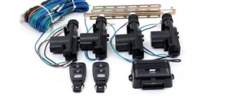
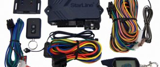
A standard car lock kit consists of:
- Electric drive (five-wire).
- Central locking.
- Two-wire electric drives.
- Control controller.
The system is operated by a key or remote control.
- The system works with any type of alarm system.
- The remote control start button is placed on the key fob for convenience.
- If your car has an alarm system and a remote control, there is no point in ordering another one - it’s better to save money.
- In addition to the doors and hatch, you can also connect the trunk of the car. It can also be controlled by remote control.
- An important feature is the recoding of safety capabilities. For example, if the speed is exceeded, the doors are automatically locked. Or set the opening sequence: first the driver's side door, and when pressed again, the rest.
TYPE E. Vacuum control
This type of system uses a compressor to open and close the door locks. Used in Mercedes and Audi cars.
Depending on what signal the compressor receives from the lock drives, they can be push or pull type.
When using this type of system, first of all, you need to find and cut the wire that controls the compressor.
WARNING. To determine the purpose of the ends of the cut wire, you should only use a voltmeter (do not use a test lamp). It is very important to identify and not mix up the ends of the wires going to the compressor and to the lock switch (you must label them). Due to an error in determining the sides of the wire, the compressor may be damaged.
NOTE. On most Mercedes Benz vehicles, the compressor control wire will be green or blue and can be found under the side panel trim near the driver's feet. This wire will have +12V when the doors are unlocked and ground when the doors are locked.
System installation
When purchasing, it is advisable to pay attention to the original kit, which is recommended by the car manufacturer, although they are not always affordable.
Most often, the choice falls on a standard universal kit, which includes:
The more expensive system is equipped with a remote control.
To install the system kit you need:
- Central locking system.
- Copper two-core wire (4 meters).
- Screwdrivers (phillips and flathead).
- Spanners.
- Ticks.
- Pliers.
- Drill + drill bits.
- Disconnect the terminals from the battery.
- Remove the door trim (remove the handle and the screws in the corners).
- Remove the plastic door screw.
- Steering wheel screws.
- Find a place to install the system (recommended - lower left corner).
- Use a drill to make holes in each door for the activators.
- Installation of lock activators, secure with self-tapping screws.
Mechanical problems
This includes various mechanical damage and loosening of rod fasteners. The limit switches may have become loose. This is associated with violations of regulatory information, destruction or even wear of parts in the actuator gearbox.
Mechanical failures include those caused by poor installation and adjustment. If such problems are observed, they should be eliminated as quickly as possible and the causes should be removed. But it is easier to replace the central lock. The price for actuators starts from two hundred rubles.
How to care for your central locking
Central locking in a car is a set of systems that provide additional convenience and safety, but it requires additional care. Problems with car locks usually arise in winter: after washing, if the locks are not properly ventilated, moisture freezes in them and grabs the rods.
To prevent this from happening, the car must be kept with the engine running, periodically forcing the locks to work, for about an hour. Or just drive around the city until the car dries out.
More information about the device and connecting the central locking in the video:
Problems in the operation of the activator electric drive
The central locking actuator is quite fragile and does not tolerate overload. The activator body, made of plastic, can easily melt if the frequency of door closing is excessively high. The duration of the control pulse also plays an equally important role. Try to always remember about the extreme fragility of the activator and not to load it during operation.
It is easy to guess that the activator is located in each individual door of the car. If the body of one of them melts due to overheating of the electric drive commutator, this becomes the cause of many problems:
- the activator on individual doors stops functioning;
- Constant overloads in a jammed electric drive cause the fuse to fail.
The actuator mechanism is entirely made of plastic. Gears can easily wear out and break during operation, or melt when the commutator overheats. As a result, when the central locking operates, characteristic creaking sounds are heard - a sure sign of imminent failure of the activators. Likewise, if the gearbox of the mechanism is humming, but the doors do not open or close.
Connecting the lock to the alarm system
Connection to the alarm depends on the type of car central locking device:
- Controlled by negative impulse.
- Controlled by positive impulse.
- Controlled by a mixed impulse (almost never found).
The type of pulse determines what charge it is connected to the car alarm.
The difficulty lies in finding the necessary wires on which the pulse is determined using a probe. First you need to check the wires coming out of the door. If they are found, the door will open or close.
If the wires are not found, you need to check the central locking unit. You can find it by listening to the relay clicking. If you manage to disassemble the block and find the impulse points, the alarm is attached here.
Another possible location for the wires is at the driver's door of the car.
For the first two types of impulse, the search is the same, you just need to set the desired impulse.
Progress does not stand still; new technical solutions and developments appear every day. In the world of automotive electronics, there are already a lot of instruments and devices that can make life easier for the driver.
On foreign cars, even older ones, you can find not only an alarm system with central locking, but also heated side mirrors, an electric sunroof, heated seats and other electronic gadgets. You can only dream about this in a Zhiguli, so in this article we will tell you how to independently install a central lock on a VAZ 2101-2107, which will be controlled using an alarm system.
Central locking is a central locking system that allows you to simultaneously close or open all car doors. The system can be remote controlled and belongs to the category of vehicle auxiliary systems.
I would like to warn you right away that the article does not claim to be the best instructions or installation method. Personal experience is described here, so you always have the opportunity to do something better, more beautiful, more convenient, and so on.
GENERAL INFORMATION
The main elements of remote locking systems are door lock drives (actuators) and controllers - special control devices.
The most common door lock drives are electric drives, which we will consider in more detail.
Special control devices, often called central locking controllers, usually installed by the car manufacturer, provide simultaneous unlocking and locking of all car doors (possibly, at first, only the driver's door) using a central button or a regular car key. (We will also include some elements built into the car alarm and used to remotely control the locks as a central locking controller).
During installation, special attention should be paid to the method of connecting the buttons (either newly installed or already installed in the car). The given diagrams of two types of buttons can help solve this problem. When one side of the double button is pressed, only one moving contact switches to the position indicated by the dotted line.
The second moving contact remains in its original position and will switch to the dotted position when the second side of the button is pressed.
When one side of the single button is pressed, the moving contact switches to the dotted position and, when released, returns to its original position.
Electric door lock drives (actuators)
Electric drives (electric motors) for door locks are available in several design options, differing in the value of traction force (from 2.5 to 6 kg).
All of them use DC electric motors and plastic (or metal) gearboxes built into a plastic housing, converting rotational motion into linear motion. The direction of translational movement of the motor output rod is changed by reversing the polarity of the supply voltage, which is how the door lock is unlocked or locked. The most common electric motors are T-shaped (“pistol”) and square types.
The electric motors of the locks are controlled by a pulse voltage lasting 1 s. Electric motors differ in the presence or absence of a contact microswitch, mechanically connected to a retractable rod. The three wires of this microswitch are led out and, together with the two supply wires of the engine itself, form the so-called five-wire “master motor”, usually installed in the front doors. The microswitch built into them, together with the control unit, ensures that the rear door electric drives are activated when the front door lock is manually unlocked/locked using a regular car door key or door button.
A type of lock is a “master lock”, which has a locking mechanism that prevents the lock from being unlocked using the door button (lever). This type of lock can only be unlocked electrically.
A complete door motor kit includes 2 5-wire master motors, 2 or more 2-wire conventional motors (without switch), and a control controller (module).
A type of electric lock drive has appeared, which has an electromechanical fixation of the output rod in a locked state, preventing the thief from opening the door using any mechanical device. The normal opening of such a lock is carried out by two successive impulses (the so-called “two-stage unlocking”). This type of unlocking is provided in the central locking controllers built into car alarm systems for both Top Line (Cel, Ireland) and Internet (Internet Auto Security, USA) systems.
Typical characteristics
Traction force, kg - 2.5-3.5; Stroke of the output rod, mm - 19; Force for manual unlocking/locking, kg - 0.25-0.14; Current consumption, A - 2-3; Control pulse duration, s - 0.7-1.5; Dimensions, mm - 134x60x30.
Central locking controllers
Purpose and types of controllers
Central locking controllers provide:
- automatic door locking when the car alarm is armed;
- automatic unlocking of door locks when the vehicle is disarmed.
Additional functions of the central locking controller can perform:
- locking/unlocking the rear door lock when locking/unlocking the front door with a car key or door lever (button);
- locking/unlocking door locks when turning the ignition on/off.
The controllers are interfaced with electric lock drives directly or through microswitches of electric door drives. Car manufacturers produce a number of cars with central locks (controllers) installed on them. The most universal controllers provide the setting of different locking and unlocking times. The main task for obtaining automatic control of door locks when installing a car alarm is the selection of the appropriate car alarm, as well as the correct way to connect it to the central locking of the car (if it is already installed).
It is necessary to distinguish between three types of car alarms with built-in central locking functions according to the capabilities they provide for controlling door locks.
First view. Car alarm with built-in full-featured central locking controller.
Such a built-in controller has two powerful relays (each with switching contacts) with a permissible current load of 10-20 A. To ensure automatic unlocking/locking of the rear door lock when opening (locking) the front door with a car key or lever (button), as a rule, two negative synchronizing inputs for connection to the “master electric drive” (Fig. 1). The total number of lock wires is 8. The car alarms SIRIO 777, CLIPPER 80/4, 80/6, MICROCAR ALARM 052. 1, SERPI STAR GR-44, SERPI STAR GR-440 and others have a fully functional controller.
Second view. Car alarms with built-in central locking have the same functions as the first type, but they do not have synchronizing inputs. The total number of lock wires is 6. This type of central lock is available in car alarms PYTHON System 80, Puranha PRM 18, Clifford XL100, Flash Point 600, Enforcer 600, Mongoose, Mega 3000, Ungo.
Third type. This type of car alarm controller has an electronic circuit with low-power outputs with a permissible current load of 200-300 mA, sufficient to connect to them, if necessary, standard relays or car central locking inputs. The number of outputs is 2. The outputs, in most cases, have negative signal polarity, but there are also bipolar ones. Low-power locking controller outputs are provided in car alarms VIPER Code Plus, Enforcer 100A5, 200A5, 300V, FORCE 7002 and others.
Standalone lock controllers
Autonomous lock controllers include devices that are interfaced with car alarms and perform the functions of a central lock. Such controllers have two main versions:
- with one control input;
- with two control inputs.
Controller with one control input
Converts the negative output of the car alarm blocking into pulse signals from the contacts of two powerful relays, one of which occurs at the moment the security mode is turned on, and the other at the moment it is disarmed. These pulses provide control of the lock motors.
The controller often has additional negative clock inputs connected to the "master" motor. This controller is used with car alarms that do not have standard outputs for central locking.
The M3 controller, which has both potential and pulse outputs, is produced by Spal, and the MC 2050 controller is produced by Autotecnica.
Controller with two control inputs
The controller is used to convert two pulsed low-power control signals into pulsed high-power relay signals. Essentially contains two standard relays with switching contacts, the windings of which are connected to the control inputs. Used to increase the power of central locking outputs for car alarms of the third type, discussed above. Controllers of this type are produced by many companies (for example, the M4 controller from Spal).
Typical characteristics
Pulse duration
- — for electric drive control: 0.7 — 7 s.;
- — for “vacuum”) control: 3.5 — 6 s.;
- — for “comfort” type control (closing windows and sunroof) — 30 s.
Current load - 15 A. Current consumption - 10 mA.
Options for central locking connection diagrams
There are seven main options for central locking connection diagrams. These options are formed depending on the polarity of control signals and the type of switches (buttons) of the central locking system. For ease of use with any type of car alarm, the diagrams of these options have, where necessary, contact designations for standard car relays. All electric drives are usually connected in parallel to each other. The only exceptions are systems that have the ability to initially unlock only the driver's door.
Selection of car alarms and connection diagrams
When choosing a door lock control option, the following sequence is recommended:
- Determine the type and polarity of control of the central lock installed on the car;
- Determine the type and polarity of the central locking switch (button);
- Determine whether a lock motor is installed in the driver's door;
- Choose the most suitable type of car alarm: with a full-featured central locking controller, with a central locking without synchronizing inputs or with low-power outputs for the central locking;
- Select the appropriate connection diagram from the options presented or modify it for your specific application.
Let's point out two simple options that may be useful.
A. The car does not have central locking. It is recommended to choose a car alarm with a built-in central locking controller that has powerful outputs from relay contacts.
B. The car is equipped with a central locking system with negative control, but it is required to control it from the car alarm. We recommend choosing a car alarm with low-power negative outputs for the central locking.
What is required to install central locking on 2 doors?
- A working and installed car alarm system with power outputs for controlling door locks.
- Activators, actuators, actuators, solenoids, electric drives or, finally, just central locks - 2 pcs.
- The wires are two-core, copper. The diameter or cross-section of each wire must be at least 0.75 square. Length about 3-4 meters.
- Plastic clamps - 10 pieces, maybe more, “in reserve.”
- Other: electrical tape, heat shrink tubing, wire cutters, screwdriver, soldering iron, solder, multimeter, drill, drill bits, electrical extension cord, etc.
Before we begin directly installing central locks, we will analyze each point above in order, in more detail.
1) In this article we will not talk about how to install an alarm yourself, but we will assume that it is already installed. The cheapest option (about 1,300 rubles) is a simple alarm without feedback.
Let's make the alarm system and central locking together
Any modern alarm unit is equipped with two relays connected to the central locking control unit. One relay is opening, the second is locking, and the circuit in the general case looks like this:
Control of central locking by supply of “mass”
In our case, the green and white cords coming from the signaling unit will be required, as indicated in the diagram. However, they will not be the only ones needed. We will connect the relay contacts to breaks in the standard wiring. This means there will be not 2, but 4 cords.
The cause of the malfunction of the central locking VAZ 2110
How quickly a person gets used to everything good. It would seem like a central lock
, such a small thing, but to what extent...
Operation of the central locking relay VAZ 2110
This relay can be used in any car, the advantages are ease of installation, as well as low cost of components.
Connection diagram for VAZ central locker
Take another look at the diagram published in the first chapter. We will connect the relay to the gap in the white and brown wires going from the microswitch to the central lock control unit. And it is obvious that it is easier to break these wires near the 8-pin connector. The same one shown at the beginning.
To avoid any questions, we will show you what should happen as a result:
Connection diagram, central lock VAZ
The common contacts are connected to the wires coming out of the microphone. The white cord continues with the brown wire coming from the door, and so on. Normally closed contacts are also used, along with normally open ones. These are the features of connecting to the VAZ central locking system.
An approximate sequence of actions performed by the installer:
- Make and lay a 4-core cable running from the signaling unit to the 8-pin connector;
We have given this sequence to emphasize once again that the relays are switched on between the microphone and the central lock control unit. There is no need to connect any additional devices. As a result, the alarm system will be able to control the state of the locks.
Remember that installation is performed by removing the negative terminal from the battery.
All wires added to the car structure must be protected (use heat-resistant tubes or electrical tape). Twisting is not the worst method to connect two wires. But it's even better to use soldering.
Installation and connection of central locks
Installing the central locking activator in the front door
Installation of the central lock should begin by removing the door trims and other elements that may interfere with installation. Then holes are drilled in each door to install a metal strip on which the door lock activator will be attached.
Having secured and adjusted the plastic activator, we move on to connecting and laying the wires. The task is to bring the wires into the car interior and connect them to the alarm unit.
In order to avoid moisture getting on the wires and further failure of activators and other devices (power windows, door lights), consider laying the wires along the door in advance.
Avoid placing wires at the bottom of the door, as this is where water tends to accumulate.
Central locking activator wire routing
When laying the wire, also pay attention to the most “problem” area, namely the place where the wires bend in the opening between the door and the body.
We disassemble the block and look for defects
Let us note once again that a significant amount of current can flow through the cords connected to the unit. We are talking about two supply wires, as well as leads connected to the motors. The approximate current value is 20 A (in a European socket there is a maximum of 15). And with such values, all parts are mounted on PCB, which cannot but lead to the destruction of the “tracks”.
Control unit, printed circuit board
To increase its cross-section, the foil track is covered with a layer of solder. But, as you can see from the photo, sometimes ring cracks form as a result, breaking the connection between the track and the terminal. Such a defect can be quickly corrected by soldering, but this is only the beginning.
Checking diodes protecting transistors
A DC relay cannot be used unless a diode is connected in parallel with the electromagnet winding. This element, that is, the safety diode, is usually located next to the relay body. So, it won't be difficult to find it.
Printed installation of BU CZ
The specified details recommend that you “ring” first: one of the “legs” is unsoldered from the board and checked with a tester. The tester itself, of course, must be turned on in the “Diode” mode:
Semiconductor testing mode
When checking in one of the connection options, the display should show “1”, in the other – from 200 to 500 mV.
Let's say that at least one of the diodes conducts current in both directions or does not conduct at all.
Then, in 99% of cases, you can do this: unsolder the relay and, with a clear conscience, throw away the block, or rather, what’s left of it. The fact is that in the event of a breakdown or rupture of the diode, all transistors fail. However, you can give the unit one last chance: having installed serviceable parts to replace the old ones, you can test it by connecting the unit “on site”. The value of the element called “diode” is not important in this case. The main thing is not to make a mistake with the polarity (it is indicated on the board).
Replacing faulty electrolytic capacitors
The part called “capacitor” is a cylinder with two taps on one side. You can simply check the functionality of the capacitor: just look at its cover and make sure that it has not lost its plane shape (not “swollen”). If the last condition is not met, the capacitor is replaced, observing the polarity of the connection.
Two parts need to be replaced
There are positive and negative terminals, and on the imported part the “minus” is indicated by a stripe on the body.
When choosing new capacitors to replace faulty ones, the following requirements must not be violated:
- The nominal voltage should be 16 Volts or more.
- Installing a part with a larger capacity than provided is strictly prohibited: you will receive a response time increased several times (instead of 0.8 seconds it will become 1.6). This will negatively affect the durability of the actuators mounted in the doors.
- The size of the new part must match the printed circuit board. This requirement, oddly enough, is the most difficult to fulfill.
If you have made repairs based on the tips outlined here, check the unit for shorts. Connect to the “Krona” supply terminal from the tester (positive terminal), and to the “ground” - negative terminal. Try applying a negative signal to each control wire - the relay should click. However, the last property is not typical for all blocks, but only for the most “primitive” ones. Typically, a control unit requires a lot of control voltages to operate.
Connection diagram for BU "Grant"
Recommendations for installing the unit in a car are standard: before performing any actions, even if it involves dismantling, you need to disconnect the negative terminal of the battery.
This is how you can protect yourself from unpleasant consequences. Any control unit, even a faulty one, acts as a “buffer” between the battery and electric motors. If the repair is carried out incorrectly, you will get a non-functional central locking (and even then, not always). And the actuators themselves, as is easy to understand, will remain unharmed in any case.

