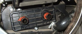
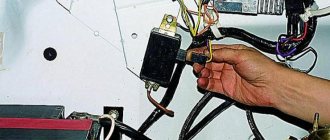
The UMZ-4216 camshaft position sensor is a device that allows you to determine the position of the gas distribution mechanism depending on the location of the crankshaft. It is used to regulate spark supply and fuel injection. The sensor transmits information to the electronic control unit, which determines the top dead center of the first cylinder and, depending on its location, supplies the fuel-air mixture.
If the DPRV is in a faulty state, then the machine will also work continuously and start when cold. But the adjustment of the fuel-air mixture injection and spark will be inaccurate, since the operation of the camshaft sensor will be replaced by the DCPV.
If the fuel and spark supply system is not configured correctly, this can directly affect the operation of the engine. The internal combustion engine may not operate correctly, oscillate and vibrate.
It is recommended to replace the DPRV every 100 thousand kilometers. Due to metal dust, exposure to bad roads and constant temperature changes.
First option
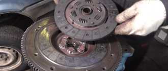
Early cars were equipped with a mechanical speedometer driven by a flexible shaft of the GV 310 model. The flexible shaft was installed at one end on the gearbox housing, and the other was attached to the speedometer housing.
The drive was carried out from a helical gear mounted on the secondary shaft in the gearbox. It is located closer to the rear shaft bearing. The speed sensor of the Gazelle in this case was the speed measuring device itself. The flexible shaft rotated the magnetic disk, creating a magnetic field. Its intensity depended on the shaft rotation speed. This field turned the spring-loaded needle. The Gazelle speedometer drive cable is shown in the photo.
Drive maintenance consisted of timely lubrication of rotating components and control over the route of the cable. The radii of cable bends should not be more than 150 mm.
Where can I buy
Spare parts and other products for the car are easily available for purchase at auto stores in your city. But there is another option that has recently received significant improvements. You no longer need to wait a long time for a parcel from China: the AliExpress online store now offers the opportunity to ship from transshipment warehouses located in various countries. For example, when ordering, you can specify the “Delivery from the Russian Federation” option.
Follow the links and choose:
| 5pcs Camshaft Fixing Tool Set | Crankshaft position sensor Gas, UAZ, ZMZ | Car acc tester KONNWEI KW600 |
| Camshaft Position Sensor for Hyundai | Car Disassembly Tool 26pcs/set | Car paint drying lamp, 1000 W |
How the speedometer works
Before we tell you how to adjust or wind up the odometer readings, let’s figure out what the operating principle of the speedometer on a Gazelle is. The principle of operation of the mechanism is to measure the speed of the vehicle through the mechanical connection of its pointer with the output pulley of the gearbox. The latter receives wheel drive.
The shaft can give a true measure of driving speed; more accurate indicators will give the wheels of the car. This is because the gearbox pulley is located further from the gearbox and closer to the wheels, and the speed at which it rotates is set in accordance with the final speed after the gearbox. The speed of rotation of the pulley may be identical in both first and fourth gear, but the difference in the speed of the machine can be colossal.
In a gearbox, the output pulley contains a gear that rotates with the pulley. The gear is connected to the speedometer drive cable. In the circuit, the cable is a durable wire located inside a protective rubberized casing. One end of the cable is installed in a special hole and fixed on the drive gear. When the gear rotates, the cable rotates with it.
The second end of the cable is connected to the device on the control panel. At the end is a magnet in the shape of a shaft, which is mounted close to the steel drum, but not in contact with it. The drum is attached to the needle and transmits readings to the corresponding scale. When the vehicle is stationary, the cable needle is kept at zero level by a small coil spring.
Scheme for making a twister
Purpose and operating principle of DPKV
The function of the device is to determine the position of the engine cardan at a certain time for computer control of actuators and coordination of the functioning of the gas distribution system. It serves to ensure the formation of impulses from the (60-2) teeth of the disk, that is, it marks the rotation of the cardan on sector marks. The angular stroke of one tooth, together with the gap to the next, is equal to 6 o of rotation of the cranked spindle. It functions in conjunction with a toothed circle located on the cardan pulley. The circle has 60 notches with 2 whole protrusions missing. The cutout on the circle serves as the starting point for the location of the crankshaft. The beginning of the 20th (behind the cutout) tooth (teeth numbering starts from the cutout clockwise) corresponds to TDC of the first or fourth cylinder.
The specificity of the action of the crankshaft sensor is the formation of an alternating current emf of a sinusoidal type in its coil when passing a metal tooth of a circle with protrusions near its end. In the middle of the protrusion (its rear cut) there is zero pulse amplitude. When passing the cutout of the gear circle, the device is silent. From this point the car computer starts counting. When the 20th notch of the ECU synchronization circle approaches, it marks the location of the pistons of the first or fourth pots at TDC. Thus, the car computer knows what is located where in the engine.
Failure of the DPKV leads to the engine stopping.
Attention! The crankshaft sensor is the most important sensor among all engine sensors. You need to have a intact, working, spare DPKV in your car.
Restyled version
Since 2003, cars began to be equipped with a new instrument cluster with an electronic speedometer. The new Gazelle speed sensor was designated DS-6 and was installed on the gearbox housing on the left side. The sensor had a mechanical drive similar to a cable. The same device was used at Gazelle Business.
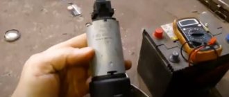
The operation of the sensor is based on the Hall effect principle. Any change in speed is recorded by a sensor and transmitted in the form of voltage pulses to the controller of the electronic control unit. They have a lower limit of about 1 Volt and an upper limit of at least 5 Volts.
There is a proportional relationship between the speed and pulse frequency, so the sensor error is small. As the speed increases, the pulse frequency also increases, but the sensor has a design limitation - the pulse counter readings cannot be higher than 6004 per kilometer. The controller calculates the speed based on the number of pulses and the time intervals between them. The received signal is transmitted to the speedometer located on the dashboard of the car. The photo shows the electronic sensor of the Gazelle.
The design of the sensor is quite simple and, in general, it does not cause problems for car owners. Replacing the Gazelle Business speed sensor is quite simple. Before starting work, it is advisable to disconnect the battery from the vehicle's on-board network. To remove the sensor, it is necessary to remove the hatch located next to the gear shift lever. The sensor can also be accessed from below. To loosen the fastening nut, a wrench with a jaw size of 22 mm is required. After loosening the nut, the sensor can be easily unscrewed by hand and removed from the drive. On the other hand, it is equipped with a regular connector with plastic latches.
Sometimes there is an oil leak through the sensor drive, which oils the contacts and disrupts operation. The drive itself is fixed with a clamping bracket, to remove which you need to unscrew one 10 mm bolt. After this, the drive can be removed from the box housing to replace the ring rubber gasket.
Cooling radiator
Auto chemicals LIQUI MOLY Gasoline additive, long-term injector cleaner - reviews
The radiator is one of the most important units. It can be 3 or 4 row. In this case, the unit is made according to the classic version, therefore it necessarily includes the following components:
- a lower tank equipped with a discharge pipe;
- central tubes, which are installed in rows;
- On top there is a tank with a supply pipe.
Radiator mounting can be three-point. In this case, special brackets are used for fastening on the sides, ensuring reliable fastening of the units. For guaranteed reliability, a bottom radiator connection is also provided.
The radiator has special shutters, which are metal plates. If necessary, blinds block access to air. To control the blinds, a special drive installed in the cabin is used, and it is enough to change the position of the existing handle. Proper adjustment helps extend the life of the cooling system. By properly regulating your radiator, you can successfully maintain your vehicle and protect it from excessive heating or cooling.
How to wind up the speedometer
GAZelle cars were equipped with speedometers of several designs:
- with mechanical drive of all elements;
- with electronic drive speed indicator and mechanical odometer;
- electronic version with LCD screen.
Depending on the type of construction, different mileage adjustment techniques are used. If the owner is not confident in his abilities and knowledge, it is recommended to contact workshops that provide such a service.
On early GAZelle cars equipped with a mechanical speed meter, adjustment is carried out by rotating the cable from the electric motor. You can wind up a GAZelle Business with early versions of electromechanical meters using a motor from a computer fan. Power is supplied from the cigarette lighter socket, a free wire with green or yellow insulation is connected to the block (to the green conductor) located above the brake pedal. After turning on the ignition, winding begins.
There are devices mounted in the cigarette lighter socket. The signal wire is connected to the instrument cluster. The device is equipped with a potentiometer that allows you to change the speed of mileage adjustment.
You can make a winding for the speedometer yourself if you know the basics of electronics and circuit design. Such a unit will work on GAZelle-3302 cars equipped with an electromechanical speedometer. The homemade design is based on the 1006VI1 microcircuit; ceramic capacitors and resistors are used. To protect the device from erroneous connection, a diode type KD521, rated for a current of 1A, is used. The device must be insulated from moisture using insulating tape.
Third option
The Gazelle Next speed sensor is somewhat different from previous models. It is electromagnetic and has four wires going to the controller. Previous sensors only had three wires. A new type of device is shown in the photo.
The sensor has part number A63R42.3843010-01, is equipped with a 22 mm nut on the housing and is screwed into the gearbox housing.
Gazelle speed sensor does not work
The vehicle speed sensor (VS) is designed on the principle of the Hall effect and outputs a frequency-pulse signal to the controller. The frequency of the signal is directly proportional to the speed of the vehicle. The controller uses this signal to control engine idle speed and, through the idle speed control, controls the air supply bypassing the throttle valve. The DSA produces approximately 6004 pulses for every kilometer traveled by the vehicle. Based on the time interval between pulses, the controller determines the speed of the vehicle. In addition, this signal can be used by the speedometer installed on the instrument panel. The appearance of vehicle speed sensor To get to the speed sensor on the Gazelle, you need to unscrew all the screws securing the hatch around the gear shift knob:
We pull out and disconnect the sensor chip. Checking the functionality of the DSA should begin with the presence of grounding on pin “3” and supply voltage (+12V) on pin “1”. The black wire is negative and the yellow wire is positive, the green wire goes to the controller and to the instrument panel, as can be seen from the diagram:
Where number 66 is our speed sensor. We also see that the positive going to our sensor comes to the reverse switch, so if the reverse lights light up when you turn on reverse gear and the ignition, then you don’t have to check the fuse.
But here is the electrical circuit, after assembling it, you can check the speed sensor itself:
Or connect another (known good) sensor to the connector, turn on the ignition and turn the sensor shaft and look at the speedometer needle, it twitches - that means everything is fine, the sensor should be replaced.
In my case there was no negative on the black wire. I cleaned it up and wound up additional mass:
I soldered the twist and insulated it well:
I passed the wire under the rubber mat and screwed it between the seats to ground:
CONNECTING THE WINDING ON UAZ, VAZ.
Purchase
To select a similar device, you need to know its number. In order not to be afraid of purchasing a completely different part, it is recommended to turn to professionals.
The DPRV is a consumable item and must be constantly replaced at least once every 100 thousand kilometers. It is inexpensive, but to save money, many people use Russian production. Russian and European ones are practically no different from each other and have an identical type of work.
The operation of the engine system will not be disrupted and it will function normally. The main thing is that the new part is exactly the same size. Much more often, Russian production makes slightly elongated products, but here too the craftsmen found their own solution. They manually cut a special gasket from paronite, which allows the internal combustion engine to function fully without causing problems.
Round connector for gazelle speed sensor pinout
GAZ 2705 | Checking the condition and replacing the speed sensor
Checking the condition and replacing the vehicle speed sensor (VSS)
1. Disconnect the sensor wiring harness connector. Using a voltmeter, measure the voltage at the connector (harness side). The positive probe of the voltmeter should be connected to the terminal of the black and yellow wire, the negative one to ground. The connector must have battery voltage present. If there is no power, check the condition of the VSS wiring between the sensor and the fuse mounting block (on the left under the instrument panel). Also make sure that the fuse itself is working properly. Using an ohmmeter, check for continuity between the black connector wire terminal and ground. If there is no continuity, check the condition of the black wire and the quality of its terminal connections. 2. Jack up the front of the car and place it on jack stands. Support the rear wheels with wheel chocks and shift the transmission to neutral. Connect the electrical wiring to the VSS, turn on the ignition (do not start the engine) and test the signal (blue-white) wire terminal on the back of the connector with a voltmeter (connect the negative probe to body ground). While holding one of the front wheels stationary, manually turn the opposite one - the voltage should range from zero to 5 V, otherwise replace the VSS.
Manufacturer
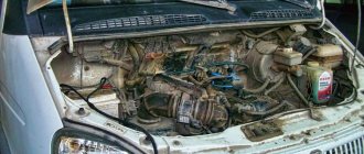
Engine 4216 is produced by the Ulyanovsk Motor Plant. Nowadays this oldest Russian plant is part of the GAZ Group holding company. UMP traces its history back to 1941. It was then, at the very beginning of the Second World War, that the capacities of the Moscow Automobile Plant named after. Stalin. The first vehicle produced by the company at the new location was the ZIS-5. After some time, the plant was renamed UlZIS.
In September 1944, the Ulyanovsk Small Engine Plant was separated from the enterprise. In the early 50s, its designers designed the first model of an air-cooled UD engine. In 1953, the company began producing Zif-5 outboard motors. Later, the plant produced a more advanced model “Veterok” for a long time.
In 1968, the Ulyanovsk Small Engine Plant was renamed UMZ. The company began assembling full-fledged automobile engines. The first UMZ engine rolled off the plant's assembly line in 1969. The company began producing gas-gasoline engines intended for commercial vehicles in 2010.
GAZ 2705 | Checking the condition and replacing the speed sensor
Checking the condition and replacing the vehicle speed sensor (VSS)
The VSS is mounted on the transmission housing and is a variable reluctance sensor that begins to produce voltage pulses as soon as the vehicle speed exceeds 4.8 km/h (3 mph). Pulses from the sensor are sent to the PCM and are used by the module to control the duration of the opening time of the fuel injection injectors and the transmission shift. On models with manual transmission, one VSS is used, on models equipped with AT, there are two speed sensors: one is connected to the secondary shaft of the gearbox, the second is connected to the intermediate shaft, and the failure of any of them leads to problems with transmission shifting.
1. Disconnect the sensor wiring harness connector. Using a voltmeter, measure the voltage at the connector (harness side). The positive probe of the voltmeter should be connected to the terminal of the black and yellow wire, the negative one to ground. The connector must have battery voltage present. If there is no power, check the condition of the VSS wiring between the sensor and the fuse mounting block (on the left under the instrument panel). Also make sure that the fuse itself is working properly. Using an ohmmeter, check for continuity between the black connector wire terminal and ground. If there is no continuity, check the condition of the black wire and the quality of its terminal connections. 2. Jack up the front of the car and place it on jack stands. Support the rear wheels with wheel chocks and shift the transmission to neutral. Connect the electrical wiring to the VSS, turn on the ignition (do not start the engine) and test the signal (blue-white) wire terminal on the back of the connector with a voltmeter (connect the negative probe to body ground). While holding one of the front wheels stationary, manually turn the opposite one - the voltage should range from zero to 5 V, otherwise replace the VSS.
3. Disconnect the wiring from the appropriate speed sensor. Using an ohmmeter, measure the resistance between the two sensor terminals. The nominal value is approximately 400 ÷ 600 Ohm, otherwise replace the sensor.
1. Disconnect the electrical wiring from the speed sensor. 2. Unscrew the mounting screw and remove the sensor from the transmission housing. 3. Installation is carried out in reverse order. Don't forget to replace the O-ring.
Water pump
The unit determines the flow, functionality and technical condition of the vehicle. To protect internal working cavities, special seals are traditionally used
To prevent breakdowns, it is important to use a lubricant, which can be used to pump in lubricant.
The water pump must have a sealed housing, and nothing should leak through the special drainage hole. Otherwise, the seals will need to be changed in the near future. The tightness of the water pump, like other units, is important for the correct use of the equipment.
Principle of operation
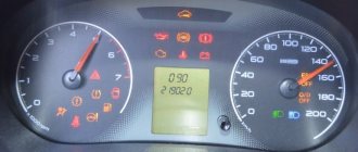
The algorithm of action for all panels is the same. Each light bulb and arrow interacts with a specific element. So, the readings of both speed and mileage come from the sensor that is screwed onto the box. Engine information comes from the crankshaft sensor. And the voltage data comes from the generator terminals. What is noteworthy: if you do not connect the voltage contact, the car will not charge even with a working generator. This problem is accompanied by a red battery light on the panel. If it lights up, it means there has been a break and the wire does not fit into the connector of the device. As for oil pressure and coolant temperature, this information comes through the terminals from the corresponding sensors.
Gazelle Speed Sensor
Gazelle speed sensor does not work
The vehicle speed sensor (VS) is designed on the principle of the Hall effect and outputs a frequency-pulse signal to the controller. The frequency of the signal is directly proportional to the speed of the vehicle. The controller uses this signal to control engine idle speed and, through the idle speed control, controls the air supply bypassing the throttle valve. The DSA produces approximately 6004 pulses for every kilometer traveled by the vehicle. Based on the time interval between pulses, the controller determines the speed of the vehicle. In addition, this signal can be used by the speedometer installed on the instrument panel. The appearance of the vehicle speed sensor is shown in Photo-1.
Cooling system features
Maintenance and adjustment of cooling system units are mandatory taking into account the technical parameters of KamAZ. The engine operates normally if the temperature conditions are maintained. Overheating and hypothermia are potentially dangerous. Incorrect temperature conditions reduce the service life of the units used. At the wrong temperature, the use of fuel is impaired, as it does not evaporate, ignite and burn well, so the engine runs with less power and consumes more fuel.
The installed KamAZ fan sensor helps in monitoring the characteristics and maintaining them under different weather conditions.
GAZelle Next speed sensor.
GAZelle Next speed sensor.
A63R42.3843010 or A63R42.3843010-01 , or A63R42.3843010-02 is installed in the car speedometer drive . The pulse sensor is designed to convert the angular speed of rotation of the speed sensor rotor into the frequency of electrical pulses. Pulse sensor.
Assignment of contacts.
| Contact | Name |
| 1 | Food “plus” |
| 2 | Food “minus” |
| 3 | – |
| 4 | Exit |
Technical characteristics of the pulse sensor.
- Rated voltage, V - 12
- Supply voltage, V - 6-16
- Current consumption at rated supply voltage, A, no more than 0.016.
When the gearbox rotor teeth move at a distance of (1.4+0.6) mm from the sensing element, the sensor provides a rectangular output pulse signal:
- low signal level, V - from 0 to 0.9;
- high signal level, V - from 4 to 16.
To check the pulse sensor, connect the sensor in accordance with the diagram. The LED should flash when the gear rotor is turned on each tooth.
Scheme for checking the pulse sensor.
1 – pulse sensor; 2 – rotor; 3 – battery; 4 – sensor plug connector; R1 – resistor with a resistance of 600 Ohms; V1 – LED.
The pulse sensor is a maintenance-free and non-repairable product, and in case of failure it is replaced with a new one.
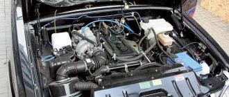
Technical characteristics of UMZ-4216
This motor belongs to the class:
- gasoline;
- four-stroke;
- four-cylinder;
- eight-valve.
Each such engine is equipped with a microprocessor-based integrated ignition and fuel supply control system. The injection in the UMZ-4216 models is phased. UMZ-4216 engines have liquid cooling.
Characteristics of the engine 4216
Fuel compression ratio
Cylinder volume working
4000 rpm at rated power, 2200-2500 rpm. at maximum torque
Specific fuel consumption
Maximum torque
The 4216 UMZ engine runs on AI-92 or AI-95 gasoline. The design of this model allows installation on GAZelle and gas equipment. The service life of the UMZ-4216 engine is 250 thousand kilometers. UMZ provides a three-year warranty on its engines (or 80 thousand kilometers).
The unfueled UMZ-4216 engine weighs 172 kg. The volume of the cooling system of this engine is 3.5 liters. The fuel supply in it is carried out in the form of distributed injection. The volume of the engine oil system is 5.8 liters.
Restyled version
Since 2003, cars began to be equipped with a new instrument cluster with an electronic speedometer. The new Gazelle speed sensor was designated DS-6 and was installed on the gearbox housing on the left side. The sensor had a mechanical drive similar to a cable. The same device was used at Gazelle Business.
The operation of the sensor is based on the Hall effect principle. Any change in speed is recorded by a sensor and transmitted in the form of voltage pulses to the controller of the electronic control unit. They have a lower limit of about 1 Volt and an upper limit of at least 5 Volts.
There is a proportional relationship between the speed and pulse frequency, so the sensor error is small. As the speed increases, the pulse frequency also increases, but the sensor has a design limitation - the pulse counter readings cannot be higher than 6004 per kilometer. The controller calculates the speed based on the number of pulses and the time intervals between them. The received signal is transmitted to the speedometer located on the dashboard of the car. The photo shows the electronic sensor of the Gazelle.
The design of the sensor is quite simple and, in general, it does not cause problems for car owners. Replacing the Gazelle Business speed sensor is quite simple. Before starting work, it is advisable to disconnect the battery from the vehicle's on-board network. To remove the sensor, it is necessary to remove the hatch located next to the gear shift lever. The sensor can also be accessed from below. To loosen the fastening nut, a wrench with a jaw size of 22 mm is required. After loosening the nut, the sensor can be easily unscrewed by hand and removed from the drive. On the other hand, it is equipped with a regular connector with plastic latches.
Sometimes there is an oil leak through the sensor drive, which oils the contacts and disrupts operation. The drive itself is fixed with a clamping bracket, to remove which you need to unscrew one 10 mm bolt. After this, the drive can be removed from the box housing to replace the ring rubber gasket.
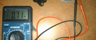
Functionality check
In order to check for functionality you will need a multimeter and a needle. First, you should clean all contacts to ensure good conductivity. After this, you need to install the needle so that it is in middle contact. We use a multimeter and point it at the working plane, the readings should instantly increase. If this does not happen, it is recommended to re-clean the contacts and repeat the procedure. If the readings are zero, the device must be replaced.
Functional
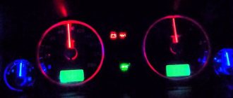
If the installation is done correctly, the new instrument cluster works properly. The only drawback is the weak backlight, which is almost invisible at night. It is recommended to install LED instrument lighting along the entire perimeter of the panel (the author of the video is Vodila Chelyabinsk).
The Gazelle is equipped with 20 indicators that indicate that one of the vehicle’s components or sensors is not working.
If the “Stop” light comes on along with one of the icons, it is advisable to eliminate the problem before starting to drive.
Using indicators, the dashboard displays information about the status of the main components and assemblies of the vehicle. A detailed description of the purpose of each of them can be found in the installation and operating instructions.
Operating rules
When working on a GAZelle with an installed UMZ-4216 engine, the driver must follow the following basic rules:
- Before starting the engine, make sure there are no leaks of coolant or fuel.
- If noises and knocks appear, you must definitely find out their cause. It is not allowed to operate the engine in this case.
- You cannot drive a GAZelle with such an engine without a thermostat in the cooling system.
During the break-in period of the UMZ-4216 engine, the following rules should be observed:
- crankshaft rotation speed should not exceed 3000 rpm;
- Do not overload the vehicle;
- the condition of the pipelines should be carefully monitored.