It is clear to anyone, not even a car owner, that without the ignition the car will not start or drive (criminal options are not considered). Depending on the car manufacturer, repairs or replacement of parts occur at a car service center or independently. Installing the ignition on a VAZ 21213 NIVA carburetor is one of those processes that the owner can carry out himself. This approach will save money and give you personal experience in repairs.
Setting the ignition timing
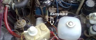
To check the ignition timing, there are three marks 1, 2 and 3 (Fig. 7-19) on the timing cover and mark 4 on the crankshaft pulley, corresponding to the TDC. piston in the first and fourth cylinders when they coincide with mark 3 on the cover.
Rice. 7-19. Location of marks for ignition installation:
1 — ignition timing mark by 10°; 2 — ignition timing mark by 5°; 3 — ignition timing mark at 0°; 4 — mark v.m.t. on the crankshaft pulley
You can check and set the ignition timing using a strobe in the following order:
- set the eccentric octane corrector of the ignition distributor to the zero position (if the engine has a P-125 V ignition distributor),
- connect the “+” clamp of the strobe clamp to the “+B” terminal of the ignition coil, and the “ground” clamp to the “-” terminal of the battery;
- insert an adapter for connecting a stroboscopic lamp between the spark plug wire of the first cylinder and the spark plug and mark mark 4 on the crankshaft pulley with chalk for greater visibility;
- start the engine, directing the flashing strobe light to the mark on the pulley; If the ignition timing is set correctly, when the engine is idling, mark 4 visible on the pulley should be opposite mark 2 on the timing cover.
To adjust the ignition timing, stop the engine, loosen the distributor mounting nut and turn it to the required angle. To increase the ignition timing, the distributor housing should be turned counterclockwise, and to decrease it, clockwise. Then check the ignition timing again.
If you have a diagnostic stand with an oscilloscope, then with its help you can also easily check the ignition timing setting, proceeding as described in the instructions for the stand.
Reinstall the ignition distributor removed from the engine in the following order:
- remove the cover from the distributor, check and, if necessary, adjust the gap between the breaker contacts;
- turn the crankshaft until the compression stroke begins in the first cylinder, and then, continuing to turn the crankshaft, align mark 4 with mark 2;
- turn the rotor to a position in which its outer contact is directed towards the contact of the first cylinder on the distributor cap;
- while holding the distributor shaft from turning, insert it into the socket on the cylinder block so that the center line passing through the spring latches is approximately parallel to the center line of the engine;
- secure the distributor to the cylinder block, install the cover, connect the wires, check and adjust the ignition setting.
Source
Preparing spare parts and tools for timing belt replacement
To adjust the marks you will need the following tools:
- screwdriver;
- wrenches for 8, 13, 10, or heads;
- device for turning the crankshaft;
- sealant;
- shoes for wheels (preferably).
The condition of the mechanism greatly depends on the driving style. The chain is much stronger than the belt, but it also does not like jerking or high speeds. Therefore, driving in a sporty style, with sharp gear changes and acceleration in extreme modes, quickly “sentences” the timing belt. And the engine, transmission, car as a whole. The condition of the chain depends on the condition of the oil, tension, and alignment of the rotating parts. Therefore, when the mileage declared by the manufacturer expires, it is necessary to change not only the chain, but the accompanying parts.
The best way to determine the need for replacement is to visually inspect the timing parts. But since access to details is difficult, we can judge by indirect signs. Such as increased noise, extraneous knocks. They can be caused by wear of the tensioner and damper, sprockets, increased play of the water pump shaft, chain stretching, and other factors. Play in the pump shaft is especially dangerous, since if it breaks down, the engine overheats and dangerous chain beating occurs.
For confident driving, along with a worn chain, it is necessary to change:
- tensioner;
- sedative;
- stars;
- crankshaft oil seal (if necessary);
- cylinder head gasket;
Replacing all of the listed parts together will allow you to confidently operate the car without worrying about the condition of the timing belt.
How to adjust the ignition on a Niva with a carburetor engine with your own hands
Unpretentiousness, ease of maintenance and maintainability are a well-known advantage of all carburetor engines that were installed on cars of the VAZ family, including the entire Niva model range. But here also lies their main drawback, namely the need for periodic manual adjustments. For example, after repairs or when changing the octane number of the fuel used, the driver is required to install the ignition on a VAZ Niva car (carburetor), while injection systems do not require such manipulations.
Installing the ignition on the Niva eliminates the problem of incorrect engine operation
Due to an incorrectly set ignition timing, the engine begins to operate incorrectly and its power decreases. Timely adoption of measures to install the ignition on a VAZ-21213 Niva with a carburetor engine can eliminate the problem. If you decide to make all the adjustments yourself, you can also save on the services of a specialist. To do this, you just need to read the guide below.
Carburetor repair for dips and jerks
Carburetor repair may be necessary if the engine idles unstable, and adjusting the quantity and quality screws does not always help. Often the reason lies in over-enrichment of the mixture, which may be a consequence of incorrect adjustment of the float system or malfunctions in the vacuum economizer system for power modes. In the latter case, a torn diaphragm may need to be replaced or the economizer valve through which fuel is leaking may need to be repaired.
Model 2121 may cause jerking, swaying or dips when moving. In this case, there may be several reasons for their occurrence, which may require carburetor repair to eliminate them. Dips that appear when the throttle valve is slowly opened are often associated with clogging of the idle jet. Here it is necessary to adjust the fuel level and check the level of clogging in the main fuel jets.
If the car gives a deep failure when trying to open the first or second throttle chambers, then in addition to clogged nozzles, the reason may be poor installation of small diffusers in the corresponding sockets.
When the Niva 21213 gives slight twitches at low and medium speeds and accelerates sluggishly, it may be due to poor fuel dosage on the shut-off valve side due to its wear. In this case, repairs are needed in terms of replacing the shut-off valve with a shut-off needle made of metal with a valve that has this needle made of a different material.
Cars of the 2121 series sometimes give failures when any sudden opening of the throttle valves, which then disappear within 5 seconds when the engine is running at the same pace. Often such problems are associated with a malfunction of the accelerator pump, which leads to a lack of or an incorrect drop in gasoline flows. A similar situation can result from a diaphragm rupture, a rubber O-ring on the sprayer holder being destroyed, or the lower part of the valve being destroyed.
If you find an error, please select a piece of text and press CtrlEnter.
How to set up the ignition on a Niva yourself
The most accurate adjustment of the ignition 21213 (carburetor) can be performed using a strobe light. However, this is not the only method available in garage conditions, especially since many car enthusiasts do not have this device at their disposal and do not intend to buy it. Therefore, we will consider two ways to set the optimal ignition timing.
First, let's focus on adjustment using a strobe light. Prepare a “13” wrench and, in fact, the strobe itself for the upcoming work. If everything is ready, you can begin to perform the adjustment operations, following the step-by-step instructions, but first we will make a reservation that for correct adjustment the engine must be warmed up and the carburetor must be properly adjusted. So, the procedure is as follows:
To adjust the ignition correctly, the engine must be warmed up.
- First, using a special wrench to manually rotate the crankshaft, install the piston of the first cylinder so that it is at top dead center. To do this, follow the special marks that are located on the crankshaft pulley and on the timing cover. The location of the piston can be considered correct if the mark on the pulley is aligned with the middle mark on the cover.
- Next you need to remove the cover of the distributor sensor to determine whether the slider is positioned correctly. If it is directed towards the first cylinder, then the piston position corresponds to the compression stroke. If necessary, adjust the position of the slider by turning the crankshaft.
- Now you should check and, if necessary, set the optimal ignition moment of the combustible mixture - prepare a strobe light for this operation. To begin with, the device should be prepared for use by connecting its “negative” wire to the ground of the car, and the “plus” wire to the positive terminal of the battery. The sensor clamp should be connected to the high voltage contact designed to ignite the mixture in the first cylinder.
- Next, start the engine, setting the idle speed (approximately 800 rpm), and position the strobe so that its flashing beam is directed towards the mark on the crankshaft pulley. During operation, it should coincide with the middle mark on the timing cover. If alignment is ensured, then your vehicle has the correct advance angle, otherwise you will have to make an adjustment.
- With the engine running, use a wrench to loosen the sensor-distributor, then slowly turn it until the marks mentioned above match. If it is necessary to increase the angle, the distributor should be turned counterclockwise, and by turning it clockwise, you can ensure a decrease in the ignition timing. After completing the adjustment, be sure to tighten the mounting nuts.
Using a strobe, you can adjust the moment of ignition of the working mixture very precisely.
This is how the ignition of a VAZ-21213 (carburetor) is installed using a device such as a strobe. With its help, you can adjust the moment of ignition of the working mixture no worse than a qualified car service specialist. Next we will consider an option that does not require the use of this device.
How to set ignition timing using a light bulb
This adjustment method does not require the purchase of additional equipment and at the same time allows for fairly accurate adjustments. If it suits you, then before you start adjusting the ignition of the VAZ-21213 (carburetor), prepare a 12 V test light by first soldering it to its contacts along the conductor. And you will also need a “13” wrench and a wrench to manually rotate the crankshaft. During the setup process, follow the sequence of steps described below:
Adjusting the ignition timing according to the light bulb must be done with the engine turned off.
- Unlike the method that involves the use of a strobe, adjusting the ignition timing using a light bulb is carried out with the engine turned off. But here it is also necessary to install the piston of the first cylinder at TDC, aligning the mark on the pulley with the middle mark on the camshaft cover. Similar to the first method, remove the distributor cap and make sure that the slider is directed to the first cylinder.
- After loosening the distributor, connect the light bulb to ground and to the low-voltage wire of the ignition coil. Don't forget to reinstall the distributor cap.
- Next, turn on the car’s ignition (the light should light up at this moment) and slowly turn the sensor-distributor housing clockwise until the warning light turns off. As soon as this happens, slowly turn the distributor counterclockwise until the light goes out again. The advance angle set in this way will ensure stable engine operation at any speed.
- All that remains now is to tighten the nuts securing the sensor-distributor.
Device
Purpose
The ignition system of the Niva 21213 car is designed for high-quality ignition of the combustible mixture. The concept of quality includes the following properties:
- Ignition at the right moment;
- Flash speed;
- Clear work.
The occurrence of a spark on the spark plug at the right time is ensured by synchronizing the operation of the ignition system with the angle of rotation of the crankshaft of the Niva 21213 car. The rate of fuel ignition depends on the quality of the spark and its position in the combustion chamber. The larger the area of contact between the spark and the mixture, the faster it will ignite. Smooth operation means uninterrupted supply of voltage to the spark plugs and formation of a spark.
System elements
Understanding the operating principle of individual components will help in troubleshooting. From the unit they move on to a specific part, which is replaced with a new one.
All components can be divided into several groups:
- Spark formation;
- Distribution;
- Synchronization.
A spark occurs due to electrical breakdown of the gap between the electrodes of the spark plug. To do this, the voltage on it must be sufficient. A number of elements are involved in the process of creating this tension:
- Switch;
- Ignition coil;
- High voltage wires;
- Distributor;
- Candles.
High voltage is supplied to the central contact of the distributor. The rotating slider distributes voltage to the spark plug of the corresponding cylinder, in which ignition occurs. Synchronization of the ignition system is implemented using a Hall sensor. It sends pulses to the switch without any mechanical contact, so the 21213 ignition system is non-contact. The metal screen, passing through the Hall sensor, creates an impulse for the switch. In this way, the moment when the high voltage begins to be created is recognized. The screen is mechanically connected to the camshaft and rotates synchronously with it. So, synchronization is carried out by the following elements:
- Distributor shaft with screen;
- Hall Sensor;
- Switch.
In addition to the above elements, the 21213 ignition system is equipped with advance angle regulators. They change the angle under certain conditions. The engine operation is being corrected. This is necessary in order to ensure optimal speed at different loads. The vacuum regulator is activated by vacuum in the carburetor diffuser; this depends on the throttle position and engine speed. The centrifugal governor changes the angle depending on the speed. Its action is based on centripetal acceleration; the greater it is, the greater the angle of advance.
Ignition adjustment
Reg.: 08/21/2012 Messages: 37 From: Russia, Buryatia, Ulan-Ude Age: 48 Car: 21213, 2000 (I've owned it since April '12)
Name: Sergey Reg.: 04/07/2016 Messages: 47 From: Tambov Age: 35 Car: VAZ 21213 1999
Reg.: 08/21/2012 Messages: 37 From: Russia, Buryatia, Ulan-Ude Age: 48 Car: 21213, 2000 (I've owned it since April '12)
Sergio
Thanks for the most complete manual. I think, besides me, it will also be useful to subsequent generations of “whys”)))
Is it possible to insert plugs into cylinders 1 and 4 at the same time? Which one fires first - that means the compression stroke is there, then?
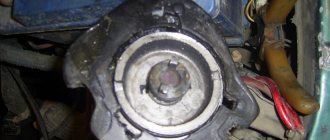
And another question - is it possible to use an internal notch (which is closer to the engine) instead of the standard mark on the pulley - it, if I understood correctly from what was written earlier, is more accurate than the external one. For me it diverges from the main one by about 5 mm.
Name: Alexey Reg.: 06/19/2017 Threads / Messages: 2 / 1705 From: Tula Age: 51 Car: VAZ-21213 1999
Name: Sergey Reg.: 04/07/2016 Messages: 47 From: Tambov Age: 35 Car: VAZ 21213 1999
Name: Georgy Reg.: 12/15/2010 Messages: 1122 From: Moscow Age: 62 Car: VAZ-21213 1997
Reg.: 08/21/2012 Messages: 37 From: Russia, Buryatia, Ulan-Ude Age: 48 Car: 21213, 2000 (I've owned it since April '12)
If I understand you correctly, you mean by the mark (notch) as in the photo?
If yes, then I'll post on it
Name: Alexey Reg.: 06/19/2017 Threads / Messages: 2 / 1705 From: Tula Age: 51 Car: VAZ-21213 1999
Name: Sergey Reg.: 04/07/2016 Messages: 47 From: Tambov Age: 35 Car: VAZ 21213 1999
Name: Georgy Reg.: 12/15/2010 Messages: 1122 From: Moscow Age: 62 Car: VAZ-21213 1997
Name: Alexey Reg.: 06/19/2017 Threads / Messages: 2 / 1705 From: Tula Age: 51 Car: VAZ-21213 1999
Name: Georgy Reg.: 12/15/2010 Messages: 1122 From: Moscow Age: 62 Car: VAZ-21213 1997
Reg.: 08/21/2012 Messages: 37 From: Russia, Buryatia, Ulan-Ude Age: 48 Car: 21213, 2000 (I've owned it since April '12)
Sergio
I set it up exactly according to this manual, everything worked! The traction is now simply drayage throughout the entire rev range. Rocket! And the main thing for me is that it stopped twitching in 1st gear at low gas (for example, when passing recumbents, it used to move like a seizure, which was extremely infuriating).
True, now it has become rather difficult to start - now it starts every once in a while (and without a boost of gas). Where should I turn the distributor?
Source
Setting the ignition timing
To check the ignition timing, there are three marks 1, 2 and 3 (Fig. 7-19) on the timing cover and mark 4 on the crankshaft pulley, corresponding to the TDC. piston in the first and fourth cylinders when they coincide with mark 3 on the cover.
Rice. 7-19. Location of marks for ignition installation:
1 — ignition timing mark by 10°; 2 — ignition timing mark by 5°; 3 — ignition timing mark at 0°; 4 — mark v.m.t. on the crankshaft pulley
You can check and set the ignition timing using a strobe in the following order:
- set the eccentric octane corrector of the ignition distributor to the zero position (if the engine has a P-125 V ignition distributor),
- connect the “+” clamp of the strobe clamp to the “+B” terminal of the ignition coil, and the “ground” clamp to the “-” terminal of the battery;
- insert an adapter for connecting a stroboscopic lamp between the spark plug wire of the first cylinder and the spark plug and mark mark 4 on the crankshaft pulley with chalk for greater visibility;
- start the engine, directing the flashing strobe light to the mark on the pulley; If the ignition timing is set correctly, when the engine is idling, mark 4 visible on the pulley should be opposite mark 2 on the timing cover.
To adjust the ignition timing, stop the engine, loosen the distributor mounting nut and turn it to the required angle. To increase the ignition timing, the distributor housing should be turned counterclockwise, and to decrease it, clockwise. Then check the ignition timing again.
If you have a diagnostic stand with an oscilloscope, then with its help you can also easily check the ignition timing setting, proceeding as described in the instructions for the stand.
Reinstall the ignition distributor removed from the engine in the following order:
- remove the cover from the distributor, check and, if necessary, adjust the gap between the breaker contacts;
- turn the crankshaft until the compression stroke begins in the first cylinder, and then, continuing to turn the crankshaft, align mark 4 with mark 2;
- turn the rotor to a position in which its outer contact is directed towards the contact of the first cylinder on the distributor cap;
- while holding the distributor shaft from turning, insert it into the socket on the cylinder block so that the center line passing through the spring latches is approximately parallel to the center line of the engine;
- secure the distributor to the cylinder block, install the cover, connect the wires, check and adjust the ignition setting.
Useful video
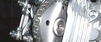
The most correct method (not the “poke method”). Remove the valve cover and turn the crankshaft until the mark on the camshaft coincides with the casting at the top (mark on the inside of the sprocket). Expose
the mark on the crankshaft is 9 degrees earlier than the long mark (TDC).
The nearest short mark is 5g, the second is 10g. That is, the mark on the pulley will be almost on the farthest short mark, slightly shifted towards the first short mark. Place the distributor in place so that the slider is directed towards the FOURTH cylinder (according to the inscriptions on the distributor cover). In this case, the latches should be approximately parallel to the motor. Lightly press the distributor with the nut, but so that it can be turned by hand. Place the cover and the wire with the grounded spark plug on the terminal of the fourth cylinder, also put the wire on the coil and on the central terminal (do not forget about the Hall sensor). Turn on the ignition
, but do not start. By turning the distributor slightly, catch the moment a spark appears on the spark plug and fix the distributor. Gather the remaining wires. To be more convincing, you can check the ignition timing using a stroboscope (100% hit).
Checking the quality of the ignition switch installation
It is logical that errors are possible when connecting contacts or incorrect installation of the lock itself. Therefore, it is necessary to test the protection in the installed state. You will need an ohmmeter and a voltmeter. Performance diagnostics:
- Checking the resistance between the terminals of the secondary winding: connect the probes to cylinders 1 and 4, then to cylinders 2 and 3. The data should approximately match. An error greater than 100 ohms indicates damage to the secondary winding.
- The wiring is checked with a voltmeter. The first control - one probe is placed on contact A, the second - on ground. Start the engine and record the data. Turn off the car and repeat the procedure with contact B. The readings should be about 12 volts.
- In addition, if there is no voltage, check the fuse, the possibility of broken wiring or corrosion of the contacts.
Our conclusions
When choosing the most reliable one, you should not always be guided by its cost. It is a common belief that a cheaper car will be cheaper to maintain. However, this is not always true. Sometimes a cheap car often has to be sent in for repairs, spending significant sums. Whereas, for example, Japanese models require practically no intervention in the first 5 years of operation. You will have to spend minimal amounts on their maintenance, including costs for fuel, maintenance and consumables.
For example, Vesta’s 3-year warranty does not apply to support bearings, shock absorbers, and neutralizers; they are only covered for 1 year. The battery is guaranteed to last 2 years. Therefore, all installation costs after the specified period are borne by the owner. If you take the Toyota Corolla, then a three-year warranty applies to all components and parts. Except in cases of independent intervention in the operation of the units. Therefore, the Japanese one will most likely be cheaper to operate.
General tips for connecting high-voltage wires.
Checking high-voltage wires. To check the wires, you will need a multimeter tester. Check the resistance of the wires - it should be no more than 20 KOhms (in practice, the longest wire of cylinder 1 has a resistance of up to 10 KOhms). If the wire resistance is more than 20 Kom, it must be replaced. Carefully inspect the wires for chafing on parts of the motor or other wires. In case of significant abrasion, replace the wire. In case of minor abrasion, it is possible to lay the wire so that it does not rub and fix it in this position.
Laying wires. Do not try to connect the wires in a bundle. Disassemble the wiring harnesses, release the wires from the plastic holders. Connect the high-voltage leads to the corresponding cylinder spark plugs. Lay the wires so that they do not rub against each other, engine parts, or hoses. Avoid sharp bends and tension on the wires. After connecting all the wires, secure them into the bundle with special comb holders included in the delivery kit.
The procedure for connecting I/O wires to a VAZ carburetor (2108, 2109, 21099)
The central wire from the distributor cover always goes to the ignition coil (bobbin).
The outlet of the distributor cover, which faces towards the front of the car, is connected to the first cylinder.
The outlet of the distributor cap, looking down, is connected to the third cylinder.
The outlet of the distributor cap, looking rearward, is connected to the fourth cylinder.
The outlet of the distributor cap, looking up, is connected to the second cylinder.
The procedure for connecting high-voltage wires to a VAZ Classic, Niva with a carburetor and distributor.
Central wire from the ignition coil (bobbin)
1 cylinder - above the vacuum corrector. Next, clockwise, the order is 1-3-4-2.
Injection VAZ produced before 2004 with an old-style ignition module (4-pin low-voltage connector)
Actually, on the module body it is already indicated which cylinder the pins correspond to - but we duplicated them in red in case the module gets completely dirty, and you might not be able to see it in the photo.
Injection VAZ produced after 2004 with a new ignition coil (3-pin low-voltage connector)
As with the old-style ignition modules, the new coils are also marked with pins corresponding to the cylinders. But the connection order is different from the order on the old-style ignition module. Be careful.
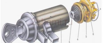
Ignition distributor sensor 3810.3706
1 – roller; 2 – housing of the ignition sensor-distributor; 3 – latch; 4 – contactless sensor; 5 – vacuum regulator housing; 6 – diaphragm; 7 – vacuum regulator rod; 8 – support plate of the centrifugal regulator; 9 – ignition distributor rotor; 10 – side electrode;
11 – cover; 12 – central electrode; 13 – ember of the central electrode; 14 – resistor; 15 – external contact of the rotor; 16 – driving plate of the centrifugal regulator; 17 – weight of the centrifugal regulator; 18 – support plate of the contactless sensor; 19 – screen.
Why does the MH break down?
The ignition module fails due to the use of low-quality spark plugs, as well as due to the use of old high-voltage wires whose insulation has lost its properties.
If the MZ gets wet, for example, by driving a Niva along a ford, then the likelihood of it breaking is quite high.
In order for the ignition module to work much longer, it is necessary to change the spark plugs and high-voltage wires on time.
Non-contact ignition system (BSZ) for 2121
Reg.: 10/25/2011 Messages: 5 From: Russia Kemerovo Age: 47 Car: VAZ 2121 1987
Reg.: 08.23.2009 Threads / Messages: 2 / 11890 From: Nizhny Novgorod region, Vyksa district Age: 36 Car: VAZ-2121 1985 VAZ-21093 1994
Reg.: 01/07/2015 Messages: 39 From: Moscow Age: 33 Car: VAZ 2121, 1988
Reg.: 10.27.2011 Topics / Messages: 27 / 2514 From: Moscow, Sokol district Age: 51 Car: NADEZHDA 2120-41 2001, 1.8; JAC Rein
Popping sounds in the carburetor when trying to accelerate is either very early ignition or lack of fuel (low level, insufficient pump, incorrect operation of the gas reducer, etc.). If the popping noise started after replacing the ignition system, check whether the distributor was installed correctly:
when aligning the crankshaft pulley along the mark, the distributor slider should look with its nose or opposite end at approximately a point located 1-1.5 cm forward from the second valve cover nut on the left side. Which end of the slider faces this place depends on which cylinder’s TDC the engine is at after aligning the marks. (Not important for testing). and is your ignition adjusted correctly?
. How to regulate - see the relevant topic or FAK, too lazy to write about this for the fortieth time.
If you had an injector, you might also suspect air getting to the throttle past the mass air flow sensor, for example through a hole in the pipe or clogged injectors. (often happens in the fall if you drive only gas all summer)
First of all, check the ignition, set it, preferably with a strobe light, and only then, if that doesn’t help, should you work on the power system.
A screw driven in with a hammer holds better than a nail tightened with a screwdriver.
Design of the ignition system of the Niva VAZ-2121 car
The ignition system is contactless. Consists of a distribution sensor, switch, ignition coil, spark plugs, ignition switch and high and low voltage wires.
The ignition distributor sensor 3810.3706 is a four-spark type, with a contactless control pulse sensor and built-in vacuum and centrifugal ignition timing regulators.
The initial ignition timing angle at a crankshaft speed of 750–800 rpm should be 1±1° BTDC.
The distribution sensor performs two main functions: firstly, it sets the moment of spark formation depending on its initial setting, the number of revolutions of the crankshaft and the load on the engine, and secondly, it distributes high voltage pulses (“spark”) among the cylinders in accordance with the order of their operation - a rotor (runner) is used for this.
In order to avoid mistakes during assembly, the slider is installed on the support plate of the centrifugal regulator in only one position.
The slider has a 1 kOhm noise suppression resistor.
The operation of a contactless sensor is based on the Hall effect.
When the ignition is turned on, power supply is supplied to the sensor. When the sensor-distributor roller rotates, a steel screen with rectangular cutouts passes through the sensor gap.
Why are timing chain marks set?
The engine of any passenger car has 2 shafts: camshaft and crankshaft. In most cars they are connected by a belt drive. On a Chevrolet Niva car this is a chain transmission, and a single-row chain is used there. The advantages of such a system are obvious: the chain, unlike a belt, never slips on the pulleys and lasts much longer. However, the chain can stretch over time, and the teeth on the shaft sprockets can wear out or even break. This will lead to desynchronization of the camshaft and crankshaft. Their work will not be coordinated, so the engine may fail. Therefore, when adjusting or replacing the timing chain, it is very important to align the engine shafts in accordance with the marks on the pulleys and timing case. This is not easy to do, since, firstly, the marks are located in hard-to-reach places, and secondly, they need to be set very accurately, since the chain, unlike a traditional belt, cannot be slightly tensioned if necessary.
How to Correctly Set the Ignition on Niva 2121
It is correct to install the ignition
VAZ 21213 ignition control
Setting the ignition time
Installation tags ignition timing
1. symbol m.t. on the crankshaft pulley; 2.7. ignition timing symbol 10°; 3. ignition timing symbol 5°; 4. ignition timing symbol 0°
Angle of ignition time up to altitude at crankshaft speed 750-800 min. 1 must comply with the information in section 1.11.
To confirm During ignition, there are three marks on the device cover 2.7, 3 and 4. time and symbol 1 on the crankshaft
, corresponding to m.t. piston in the first and fourth cylinders, which correspond to mark 4 on the cover.
You can check and set the ignition timing using the overhead mechanism. the following order:
Ignition installation. It is so simple
Dear subscribers, I bow a little, Sergiy, he is KORSUN STUDIO. For his uninteresting help in my layout.
How do you get the ignition on a VAZ Classic.
Creator: Valera Potapenko vk.com/id66558974 Send the video by email Or contact us.
To adjust the ignition timing, stop the engine and loosen the lock nut. Distribute the ignition sensor and turn it to the desired angle. For an angular increase in ignition time, the distributor body should be turned counterclockwise and decreased clockwise. Next, determine the created ignition time again.
To easily adjust the ignition timing, divisions and “” and “-” signs appear on the distributor flange during ignition. One flange fits eight degrees of crankshaft rotation.
If there is a diagnostic screen with an oscilloscope, then you can use it to simply check the ignition timing setting based on the abstract for using the shield.
Remove the distributed ignition sensor from the engine in the following order:
Diagram: ignition system Niva 21213
On Niva 21213 cars with a carburetor engine, a contactless ignition system with a switch and a Hall sensor in the distributor is installed.
1. Generator. 2. Battery. 3. Connection block. 4. Ignition coil. 5. Switch. 6. Hall sensor. 7. Ignition distributor (distributor). 8. High-voltage wires (armored wires). 9. Ignition relay. 10. Ignition switch. 11. Spark plugs.
— To successfully operate the ignition system of a Niva 21213 car, you must constantly carry with you some of its parts, without which it will not be able to work - a switch and an ignition coil.
More articles on the electrical equipment of the Niva 21213 car
BMW million-dollar engines
BMW M60 is a Bavarian engineering masterpiece. It was proposed to install engines of two versions in this car. Three and four liters. V-8. These engines were produced from 1992-1996 and also had enormous resources. Having replaced the inline six-cylinder engine of the BMW M30, it was decided to reduce the weight of the engine. The motor was made in a lightweight version; all two parts of the blocks were made entirely of aluminum. As for the liners of each cylinder, they had a virtually wear-free coating in terms of mechanical impact. But there is one nuance in terms of fuel; the cartridges are exposed to harmful properties due to the sulfur content in gasoline. Now these standards, in terms of combustible fuel, have changed a lot compared to the 90s, where the sulfur content was the lowest, and the engine felt much better and worked longer.
It is worth noting that disputes over the reliability of these engines are still relevant. Mileages of 600 thousand without repairs are not uncommon for these engines. Many specimens run up to a million kilometers, or even more. These engines were installed on BMW models of the fifth and seventh series, from 1992 to 1996.