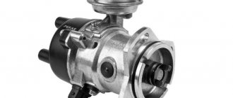
A distributor is a device responsible for producing a spark at the right moment. The part is installed on internal combustion engines. When the piston is at the top point, ignition occurs.
A distributor is a breaker-distributor. Without it, not a single gasoline internal combustion engine can operate. You can find this device on cars such as:
Without a distributor, the timely formation of a spark in the engine cylinders would be impossible.
PURPOSE OF THE DEVICE
One of the most important subsystems of a gasoline engine is the ignition system. The fact is that normal operation of the engine is possible only if the combustion of the fuel-air mixture occurs in a timely manner. Otherwise, the entire work algorithm is disrupted.
During operation of the device, voltage is generated. It is served on candles. It is on them that the spark necessary to ignite the mixture is formed. As a result, the engine starts working and the car moves in the right direction.
For all the processes described above to become a reality, a distributor is needed. In this system it performs the following functions:
- Acts as an initiator of spark formation. This occurs due to the opening of contacts.
- The device directs the generated voltage to the desired spark plug.
- The distributor can, if necessary, change the moment of sparking. This parameter is determined by the driving mode selected by the driver. Also, a lot depends on the quality and type of fuel.
- The device is capable of storing energy in a bobbin.
As you can see, the part performs many functions. It is not surprising that without its normal operation, the operation of the engine is impossible.
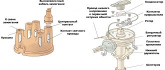
Distributor design
The distributor circuit assumes the presence of such elements as:
- low voltage current breaker;
- high voltage current distributor;
- centrifugal ignition timing regulator;
- vacuum ignition timing regulator.
The distributor circuit is designed so that at a certain moment the breaker opens the primary ignition circuit, as a result of which a high voltage current is created in the secondary winding of the ignition coil. Through the distributor, this current is transmitted to the spark plugs in certain cylinders. The regulators automatically adjust the ignition timing, which depends on the current operating mode of the engine.
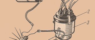
The distributor breaker is an electromechanical part and consists of the following parts:
- shaft;
- movable contact plate;
- movable contact plate;
- capacitor;
- frame.
The breaker shaft consists of two main parts. On one of them, depending on the type of breaker, cams are installed, the number equal to the number of cylinders in the engine. This distributor device is not very reliable, since a large number of contacts, as well as the presence of moving parts, lead to regular problems with this unit.
The distributor device, as well as its use in general, are outdated from the point of view of modern electrical equipment, but in our country there are still a lot of carburetor engines, so the problem of the performance of this unit is currently relevant.
As for where the distributor is located in the car, most often it can be found under the hood next to the engine, near the cylinder head or on it. Although the exact location of the node depends solely on the model of the machine.
About the drive mechanism
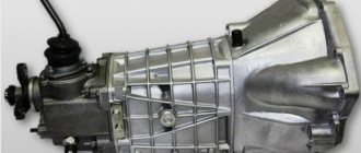
To transmit torque to the distributor shaft on the “six”, a helical gear is used, rotated by a timing chain (in common parlance – “pig”). Since the element is located horizontally and the distributor roller is vertical, there is an intermediate element between them - the so-called mushroom with oblique teeth and internal grooves. This gear simultaneously drives 2 shafts: the oil pump and the distributor.
More information about the design of the timing chain drive: https://bumper.guru/klassicheskie-modeli-vaz/grm/kak-vystavit-metki-grm-na-vaz-2106.html
The distributor transmission consists of two helical gears
Both transmission links - the “hog” and the “fungus” - are designed for a long service life and are modified during engine overhauls. The first part is removed after disassembling the timing chain drive, the second is pulled out through the upper hole in the cylinder block.
The VAZ 2106 distributor, equipped with a contact switch, is a rather complex unit consisting of many small parts. Hence the unreliability of operation and constant failures of the ignition system. The non-contact version of the distributor creates problems much less often, but its characteristics are still inferior to modern ignition modules, which have no moving parts.
Operating principle of the distributor
In many ways, the operating principle of the distributor remained unchanged for many years. In VAZ cars, such as VAZ 2109, 2106, 2107, 2108, an ignition system of this type was used almost until the end of the last century.
The basis of the work is the connection of the distributor with the engine crankshaft. When the piston in the first cylinder takes the position corresponding to TDC, the breaker contacts open, a high voltage appears in the ignition coil, directed through a slider located in the distributor cover to the spark plug of the first cylinder.
There the combustion of the fuel assembly occurs, and the crankshaft continues to rotate. In addition to moving the pistons, it causes the breaker cam to rotate. When in another cylinder another piston occupies a position corresponding to TDC, at this moment the breaker contacts in the distributor open again, and a high-voltage voltage is generated in the ignition coil and supplied to the desired spark plug.
This joint rotation of the crankshaft, the breaker cam and the distributor slider ensures that a spark appears where and when needed. However, this does not cover all aspects of how the distributor works. To understand its operation, it is necessary to touch upon such concepts as the angle of the closed state of contacts (UZSK) and the ignition timing angle (IAF)
UZSK
A concept such as UZSK characterizes the time when the breaker contacts are closed. In essence, this is an indirect characteristic of the accumulation of energy in the coil after the completion of spark formation. UZSK directly affects the amount of energy spent on sparking and, accordingly, on engine operation.
In cases where the distance between the contacts is small, the coil will not accumulate the necessary energy and the spark energy will be low, which will lead to interruptions in the operation of the motor. A large gap also leads to interruptions, since the contact breaking time is reduced and the coil does not have time to fully discharge.
Each ignition system has its own optimal UZSK, to ensure which, if necessary, the distributor must be checked and adjusted.
UOZ
This concept concerns the moment of ignition of a fuel assembly. The fact is that its combustion does not occur instantly, and often, to ensure optimal conditions for such a process, it must begin earlier than the piston reaches the TDC position. The OZ characterizes the time by which the appearance of a spark precedes the appearance of the piston in the TDC position.
Setting the angle of the closed state of the breaker contacts
The angle of the closed state of the contacts of the switch (UZSK) is, in fact, the space between the contacts of the switch. Due to constant loads, it is lost over time, which leads to disruption of the ignition process. The UZSK regulation algorithm is as follows:
- Disconnect the high voltage cables from the distributor cap.
- Unscrew the two fasteners that secure the lid. Remove the cover.
After adjusting the UZSK, the ignition timing is always lost, so it should be installed before assembling the distributor.
Video: setting the gap between the breaker contacts
DETAILS ABOUT THE MOST IMPORTANT ELEMENTS OF THE TRAMBER DEVICE
VACUUM REGULATOR
It is this device that can change the OZ if necessary. As soon as the motor load changes, appropriate adjustments are made to the operation of the distributor device parts.
The vacuum regulator of the distributor is a closed cavity. To ensure better performance, the design is divided by a diaphragm. One cavity goes directly to the carburetor.
When a vacuum occurs, the diaphragm begins to move. As a result, pressure is exerted on the movable disk and the breaker cam. The response time of the latter is adjusted depending on the current situation.
How to repair a VAZ distributor
The distributor or breaker distributor is a rather complex device and this causes a lot of trouble for the car owner. The distributor is installed on carburetor engines of cars. We will now look at how to repair a VAZ distributor yourself and what is needed for this.
Repairing a distributor of a VAZ car, as a rule, consists of replacing worn parts of the device.
How do you repair a distributor?
- Socket wrenches for “7”, “10” and “13”;
- Two Phillips screwdrivers;
- Special set of flat probes;
- Hammer;
- Special mandrels designed for pressing out and pressing distributor bearings;
- Tweezers.
First, you need to unscrew the 2 screws securing the distributor breaker rotor to the support plate from the ignition timing regulator, then remove the distributor rotor.
Before removing everything, you need to put marks on the springs and weights of the distributor, this will make it easier for you to assemble the distributor (distributor breaker). Using a screwdriver, remove the distributor centrifugal adjuster springs.
Then you need to unscrew the nut securing the ends of the condenser wires and the ignition coil. Remove the distributor capacitor by unscrewing the fastening screw. First, unscrew the screw to secure the moving contact wire, and then you need to remove the insulation, after which we remove the insulating and metal washers.
It is necessary to remove the moving contact from the axis of the contact group, then the lock washer securing the vacuum rod from the moving axis of the distributor.
Remove the rod of the vacuum regulator of the distributor, which is located on the axis of the movable plate of the distributor.
Then we remove the distributor shaft from the housing and unscrew the two screws securing the bearing plates.
In the housing we find a movable plate and a bearing, take them out. We check the condition of the distributor shaft. We examine the distributor roller for wear and we must take into account the fact that significant wear of both the shaft and the roller cams is not allowed.
We take a device for measuring capacitances, with which we check the capacitor. The capacitance of the distributor capacitor should be within the normal range of 20-25 µF.
Next, we check the technical condition of the vacuum chamber diaphragm. The diaphragm is checked by pressing the rod and plugging the fitting. In this case, the diaphragm must maintain thrust.
Make sure that the contacts of the breaker are clean, without traces of dirt; if there are any, clean and rinse the contacts with alcohol.
If the distributor housing bushing is worn, replace it. The housing bushing is also called a bearing. To press out and press in the housing bearing, mandrels are used.
Reassemble in the reverse order of disassembly, taking into account all the nuances and features.
The gap between the breaker contacts should be within 0.35-0.45 mm. If there is a discrepancy, adjust the gap between the breaker contacts.
Lubricate the fillet and spline part of the distributor shaft with engine oil.
OCTANE-CORRECTOR
This is a very important element in the distributor design. Without it, the entire system could not function normally. The unit changes the SOP depending on the fuel that is currently being used.
By its design, this distributor element resembles two plates with an arrow. The same arrow is installed on the engine. There are special lines on it, through which the ignition angle is adjusted. It is almost impossible to do without this part when refueling different types of gasoline.
Distributor malfunctions
The following signs indicate that the distributor is malfunctioning:
When there is a spark on the central wire, but not on the spark plug wires, this indicates a breakdown of the slider.
- the car jerks periodically when driving;
- Unstable engine operation at idle;
- the engine does not start at all;
- the knocking of the piston fingers is heard while accelerating;
- the speed increase dynamics decreased;
- fuel consumption has increased.
In most cases, the causes of distributor failure are:
Breakdown of the roof and ignition coil occurs due to large gaps in the contacts of the distributor cover and slider, spark plugs and bad candlesticks.
- burnout of the runner;
- oxidation or shorting of contacts under the cover;
- breakdown of the distributor cover;
- failure of one of the sensors;
- problems with the shaft bearing and other problems.
In each of these cases, replacement is required. But at the same time, for almost any car, it is possible to change not the entire distributor, but only its failed part, which is an advantage, since it significantly reduces the cost of repairs.
The most basic check of the distributor is a visual assessment of the condition of the slider, contacts and cover.
In a contactless distributor, the main malfunction is the failure of the hall sensor or inductive sensor.
To check the ignition system and distributor, among other things, observe the spark on the unscrewed spark plug after starting the engine. In garage conditions, you can also check using measuring instruments or indicators.
The distributor capacitor is also one of the parts that often fail. It helps to increase the voltage supplied to the spark plugs when the engine starts. And in order to check it, you need to disconnect it and touch the “ground”, and if a characteristic crackling sound is heard and a voltage drop is observed, the capacitor is working, if this does not happen to the replacement part.
A distributor is always a dismountable unit that can be disconnected, removed from the car, disassembled into components, a problem can be detected and eliminated by replacing the damaged part.
The design and principle of operation of a distributor breaker or distributor - video
Some owners of classic cars of the VAZ 2101-07 family are constantly trying to improve, modify, add electronics and convenience. One of these improvements is the installation of contactless electronic ignition.
Switch
The commutator is necessary to create an electrical impulse by interrupting the constant supply of current from the battery to the primary winding of the coil. The BSZ VAZ 2107 uses a switching device of type 3620.3734. The working elements in it are ordinary bipolar transistors, which open the circuit when a signal is received from the Hall sensor.
Switch 3620.3734 is built according to a simple single-wire circuit, in which the device body is connected to the vehicle ground and, accordingly, to the negative terminal of the battery. The advantages of using this unit instead of a traditional breaker include:
- no need for maintenance or adjustment;
- high spark energy, which makes it easier to start the engine in the cold season, as well as the ability to use gasoline with a lower octane number;
- the presence of a stabilization system that protects the Hall sensor from voltage surges.
Which ignition is better: contactless or contact?
Contact ignitions are obsolete, but are still used in older cars. On rear-wheel drive VAZ models, contactless was first installed on 2107.
Let's look at the differences between contact and non-contact ignition:
Advantages of contactless ignition:
- since there is no contact group in the distributor, sparking occurs clearly;
- long coil life;
- at medium engine speeds, BSZ creates a spark 4 times more powerful than contact ignition. This is especially useful if the spark plugs are dirty, as a spark will still be produced;
- performs its functions perfectly even in cold weather;
- if the voltage in the electrical network is low, then sparking will still occur;
- thanks to the powerful, stable spark of the candles, the fuel-air mixture ignites faster;
- if BSZ is installed, then fuel consumption decreases and engine power increases;
- improved vehicle acceleration dynamics;
- BSZ is easier to maintain because the device has no moving parts.
A classic and original way to strip contacts
Here's what you need to do with the standard, classic version of stripping:
- The terminal from the battery is removed.
- The chips and armored wires going to the distributor are removed.
Attention. It is recommended to write down the wires by numbers so that when you put them in place after the operation is completed, you do not get confused.
- Remove the distributor cover using a 5.5 socket.
- Visually inspect the slider, which should not interfere with work.
Advice. If the slider interferes with stripping, it is recommended to put the car in 5th gear and push it forward a little. The runner will then stand up as needed.
- The slider and contacts are thoroughly cleaned first with large HDD paper, and then with fine paper.
Note. You must act slowly, without pressing hard.
- The wires are put in place.
Replacing the distributor contact system
Stable current is the goal of this repair. You can cope with such cleaning of contacts in just fifteen minutes.
An original way to strip contacts without removing VSKV wires.
- The lower screw is removed (if it does not lend itself, process the VD).
- The inside of the cover provides access to the contacts.
Note. White deposits on the contacts once again prove the need for cleaning.
- The plaque is carefully removed with a knife.
- The contacts are treated with fine sandpaper.
The effect should make itself felt immediately after starting the internal combustion engine. The car will become faster already in the first meters of driving.
Non-contact ignition system device
The BSZ device for carburetor engines consists of:
- Distributor. This is a device that is responsible for creating a spark at the right moment. It is also called the ignition system distributor.
- High voltage coil. This element in the ignition system receives low voltage from the battery, converts it and supplies high voltage. Therefore, high-voltage wires come from it. The coil consists of two windings. The primary one is made of a large cross-section wire (connected to the electrical part of the car via the ignition switch relay), the secondary one is made of many turns of thin wire (connected with a high-voltage wire to the distributor).
- Switch. This element of the contactless ignition system is responsible for the formation of a spark. In simple words, a switch is a signal amplifier. The switch is only available in the ignition system of internal combustion engines with a carburetor. By the way, SOLEKS is considered the best carburetor. On injection VAZ 2107, as well as on others, a switch is not needed, since its functions are performed by the on-board computer controller.
- High voltage and normal wiring. High voltage wiring must meet heavy insulation requirements.
- Terminals. Serve for connections and must be strong.
Electronic and contactless ignition systems are the same device. It got its name due to the absence of a contact group in the system design. The ignition switch also has a contact group, which is a common cause of engine failure.
Hall Sensor.
The main component of the VAZ-2110 distributor is the Hall sensor. The Hall sensor works as follows. If a current is passed through a semiconductor located in a magnetic field, then an emf will appear on the edges perpendicular to the current and magnetic flux, which disappears in the absence of magnetic flux. In the distributor, the sensor is located on a movable plate and has two parts separated by a slot.
On one side of the slot there is a semiconductor with a signal amplifier and voltage stabilizer, and on the other there is a permanent magnet creating a magnetic field. A curtain with 4 slots and attached to the distributor shaft passes through the sensor slot. When the shaft rotates, the curtain rotates. When the shutter slot is located in the sensor slot, its semiconductor enters the magnetic field of a permanent magnet and an EMF appears on it, which passes through the amplifier and opens the power transistor of the sensor. When a shutter tooth passes by the sensor, the latter isolates the permanent magnet from the semiconductor, which leads to shunting of the magnetic field and the EMF on the semiconductor disappears, which leads to the closure of the transistor and the loss of voltage at the control terminal of the sensor.
Electronic ignition connection diagrams: VAZ 2101-VAZ 2107
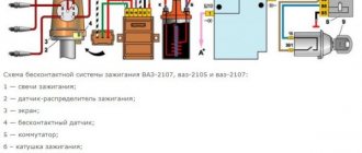
Scheme of a contactless ignition system for VAZ cars:
1 - switch; 2 — ignition coil (bobbin); 3 — distributor; 4 — ignition key; 5 - Hall sensor.
How contactless ignition works
The sequence and principle of operation of the BSZ is as follows:
- The driver turns the ignition key.
- The circuit is closed and constant voltage from the battery is supplied to the primary winding of the ignition coil. The energized primary winding forms a magnetic field around itself.
- When the starter starts, it begins to rotate the crankshaft of the internal combustion engine and rotates the shaft, which is located inside the distributor along with the slider.
- The hall sensor detects how the distributor shaft rotates (along the protrusion on the shaft) and transmits a signal to the switch.
- The electronic unit turns off the voltage supply to the primary winding based on the signal from the Hall sensor.
- When the voltage supply circuit is interrupted, at that moment a high voltage pulse of up to 24 kilovolts appears in the secondary winding of the coil, which is transmitted through a thick wire to the slider (the moving part of the distributor).
- Fixed contacts are built into the roof. The runner throws an impulse onto one of these stationary contacts. From the contact that received the high voltage pulse, it is transmitted through high-voltage wires to the spark plugs of those cylinders in which the pistons are at top dead centers.
- When voltage is applied to the spark plug, the working combustion chamber of the cylinder already contains fuel and air in a compressed state for ignition.
- The distributor slider rotates to spark all spark plugs according to a certain sequence pattern: 1-3-4-2. Depending on how to install the slider, the entire operation of the system depends, early ignition or later, we learned to determine in another material.
- The car engine starts.
ECMs are sometimes interchangeable, but sometimes they are not repairable.
Diagram of an outdated VAZ ignition system (without switch)
This scheme is in systems where there is no switch. The circuit is broken mechanically using a breaker.
Disadvantages of contact ignition:
- The contacts burn and oxidize, which reduces the power to create a spark.
- There are wear parts that are recommended to be changed every 20 thousand km. mileage
- Converted power in contact systems is up to 18 kilovolts. For electronic or contactless ones - up to 24 kilovolts.
Disadvantages of contactless ignition:
- The Hall sensor cannot be repaired. Working service life up to 50 thousand km. mileage
Contact distributor
All models and modifications of Zhiguli were equipped with contact type distributors until the early 90s of the last century. A distributor with serial number 30.3706 was installed on the VAZ 2107.
A contact distributor is no different in appearance from a contactless one.
Design of contact breaker-ignition distributor 30.3706
The contact distributor consists of the following elements:
- frame;
- rotor (shaft);
- slider (rotating contact);
- contact breaker;
- capacitor;
- centrifugal and vacuum ignition timing regulators;
- cover with main (central) and four side contacts.
The difference in the design of contact and non-contact distributors lies only in the device that generates the impulse
Housing and shaft
The base of the device is cast from aluminum. A cermet bushing is pressed into its upper part, playing the role of a support bearing for the distributor shaft. The side of the housing is equipped with an oiler through which the bushing is lubricated in order to reduce the friction force. The lower part of the shaft (shank) has splines for connecting additional engine elements to the drive gear. With their help it is set in motion.
The shaft of the device is driven by the drive gear of additional engine units
Runner
A slider is installed at the top of the rotor. It is made of plastic and has two contacts connected through a resistor. Their task is to receive voltage from the coil through the central electrode and transfer it to the side contacts of the distributor cap. The resistor is used to eliminate radio interference.
The slider has two contacts connected to each other through a resistor
chopper and capacitor
The breaker mechanism includes a group of contacts and a cam with four protrusions. The contacts are fixed on a movable plate, the rotation of which is ensured by a ball bearing. To be able to adjust the gap between the contacts, one of the mounting holes is made in the form of an oval. The moving contact is located on a spring-loaded lever. The other contact is stationary. In a calm position they are closed.
The cam is the thickened part of the shaft. Its protrusions serve to actuate the moving contact. When the breaker-distributor shaft begins to rotate, the cam with one of its protrusions rests against the movable contact block, moving it to the side. Then the protrusion passes the block and the contact returns to its place. This is the simple way to close and open the low voltage circuit in the contact ignition system.
The pulse is formed by opening the breaker contacts
Despite the fact that the voltage on the contacts is small, when they open, a spark is still formed. In order to eliminate this phenomenon, a capacitor is installed in the breaker circuit. It is attached with a screw to the distributor body.
The capacitor prevents the formation of a spark at the contacts during their opening
Centrifugal regulator
The primary adjustment of the moment of spark formation in VAZ 2107 cars is carried out by turning the entire distributor . Further adjustments are made automatically. The function of the centrifugal regulator is to change the ignition timing depending on the number of engine crankshaft revolutions.
The basis of the mechanism design is the support and drive plates. The first is soldered to a bushing that is movably fixed on the distributor shaft. It can rotate relative to the shaft with an amplitude of 15°. On top it has two axles on which weights are installed. The drive plate is mounted on the upper end of the shaft. The plates are connected to each other by two springs of different stiffness.
The centrifugal regulator adjusts the ignition angle depending on the crankshaft speed
When engine speed increases, centrifugal force also increases. It first overcomes the resistance of a softer spring, then a stiffer one. The weights rotate on their axes and rest against the support plate with their side protrusions, causing it to rotate together with the slider to the right, thus increasing the ignition timing.
Rotation of the support plate is ensured by centrifugal force
Vacuum regulator
The vacuum regulator is attached to the distributor body. Its role is to adjust the ignition angle depending on the load on the power plant. The design of the device consists of a reservoir, a membrane with a rod located in it, as well as a hose through which the regulator is connected to the primary chamber of the carburetor.
The vacuum regulator adjusts the ignition angle depending on the engine load
When a vacuum appears in the carburetor, it is transmitted through a hose to the reservoir of our device. A vacuum is created there. When this happens, the membrane moves the rod, and it acts on the rotating breaker plate, turning it counterclockwise, increasing the ignition timing.
The chopper plate rotates under the influence of vacuum created in the carburetor
Contact type distributor malfunctions and their symptoms
Taking into account the fact that the distributor is a rather complex device, it is subject to the influence of a number of negative factors that can damage the elements of its design. That is why the distributor can have a lot of malfunctions. Well, as for common device breakdowns, they include:
- electrical breakdown of the lid;
- wear of the central electrode or side contacts of the cover;
- burning of the slider contacts;
- electrical breakdown of the capacitor;
- violation of the gap between the contacts of the breaker;
- wear of the moving plate bearing.
If the contacts are severely worn, the cover must be replaced
Each of the listed malfunctions has its own symptoms, but in most cases they are of the same nature. If the distributor cover is punctured, its contacts or the slider contacts are worn out or burned, engine performance will deteriorate. The same thing will happen if the gap between the contacts of the breaker is broken, they become dirty or burnt. In this case, the following are most often observed:
- vibration;
- overheat;
- misfires;
- change in exhaust color;
- rare “lumbago” in the gas exhaust system;
- increase in gasoline consumption.
You can replace a faulty slider yourself
Failure of the moving plate bearing may be accompanied by a characteristic whistle or squeal coming from under the cover.
Selection of BSZ
When purchasing a new BSZ, you should pay attention to the presence of the components of the entire kit. The factory kit should contain:
- Distributor (main distributor). The code for engines 1.5 and 1.6 is 38.37061. For 1.3 engines, the number will be 38.3706–01, because the height of the 1.3 engine block is lower and the distributor shaft is shorter.
- Switch number 36.3734 or 3620.3734.
- High voltage coil (reel). Marking 27.3705
- Thin wires with connectors.
In appearance, the BSZ kit for the VAZ 2121 NIVA is very similar. But it’s better not to install this kit on a VAZ 2107 or a VAZ 2106, because the characteristics of the “six” and “seven” are very different from the “Niva”. Distributor brands for Niva: 3810.3706 or 38.3706–10.
The best manufacturer of electronic ignition systems for old VAZ cars is. The production capacity base is located in the city of Stary Oskol. According to reviews from car owners of classic BSZ SOATE models, this is an excellent option.
Prerequisites for failure
Please note that the engine control system malfunction warning lamp, located on the device panel in the signaling unit, is the first indicator of deviations in the operation of the VAZ 2107, where an injector is used. Some modifications of the VAZ 2107 provide for the location of the warning lamp on the upper insert of the radio panel. By starting the ignition, a system malfunction is tested, which means the lamp lights up and goes out after the engine starts.
A prerequisite for diagnosing the ignition system is that the lamp does not go out when the engine is running.
By starting the ignition, a system malfunction is tested, which means the lamp lights up and goes out after the engine starts. A prerequisite for diagnosing the ignition system is that the lamp does not go out while the engine is running.
In situations where there is a malfunction, VAZ 2107 owners replace the spark plugs. Old factory spark plugs are usually replaced with iridium spark plugs from NGK or Denzo. Do not forget that only those spark plugs that are designed for the appropriate type of injection are suitable here.
The type of ignition system is no less important in determining the parameters of the spark plug. Often such manipulation does not provide much improvement (plugs have a fairly long service life), so the non-contact ignition system undergoes a full diagnosis.
Do you want to know more about how to install
valve timing according to marks on VAZ 2101- VAZ 2107
? And so.
Installation of contactless ignition for VAZ 2107, 2106
To install the BSZ with your own hands, you will need the following tools:
- Screwdrivers (flat and Phillips);
- Open-end wrenches 8, 10, 13 mm;
- Pliers (pliers);
- Candle key;
- Drill or screwdriver with a drill diameter of 3-3.5 mm. You will have to drill two holes in the body to secure the switch.
- A special wrench for rotating the crankshaft of an internal combustion engine or a regular open-end wrench of 30 mm.
An inspection hole for installing the ignition is not required. Here, in fact, is the procedure for removing the old contact ignition:
- Open the hood, disconnect the battery and disconnect the high-voltage wires from the spark plugs.
- Unscrew the spark plugs.
- Rotate the engine crankshaft until the piston in the first cylinder reaches top dead center (TDC). You can use a long screwdriver or wire to check where the piston is located. Make sure that the mark on the engine crankshaft pulley coincides with the very first long mark on the cylinder block.
- Disconnect the latches of the distributor cover and remove it with the wires. Draw a mark on the valve cover opposite the slider.
- Disconnect the hose coming from the carburetor and all distributor wires.
- Unscrew the fastening nut and remove the distributor along with the gasket.
- Unscrew the coil mounts (remember which wires are attached where) and remove it.
The procedure for installing contactless electronic ignition on a VAZ 2106-2107.
- Drill and attach the commutator next to the coil. But, do not place it under tanks with liquid.
- Remove the cover of the new distributor and put on the gasket.
- Install into the seat for the distributor so that the moving contact is opposite the drawn mark on the valve cover. Do not immediately tighten the nut all the way.
- Install the new coil where the old one was. The wires from the ignition switch relay, tachometer, and switch must be connected to the reel terminals. The wire from the electronic unit number 1 is connected to the coil terminal marked “K”, the wire from the 4th contact is connected to the coil terminal marked “B”.
- Check the gaps of the spark plugs (should be 0.8-0.9 mm) and screw them in place.
- Snap the distributor cover and connect the high-voltage wires (the central one from the coil and 4 wires to the spark plugs). We connect the wires to the spark plugs strictly in accordance with the designations.
- Connect the vacuum hose.
After installation in the correct sequence, we start the engine and begin setting up the ignition. If after installing a new electronic contactless ignition the engine does not start, you should check the correct connection of the coil wires and the high-voltage wires to the spark plugs. If the wires are normal, then the marks are not aligned.
Instructions for setting up the ignition
The cause of engine overheating and loss of power may be late ignition. This may manifest itself as popping noises in the intake manifold. Therefore, you need to know how to install the ignition correctly (the author of the video is Nail Poroshin).
Installation is carried out according to the marks as follows:
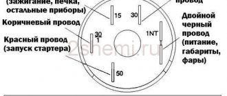
- First, you need to set the piston on the first cylinder to TDC and align the installation indicator mark with the mark on the crankshaft pulley.
- Next, the crankshaft must be turned counterclockwise until the marks 9 on the pointer coincide with the marks on its pulley.
- Then you need to loosen the bolt on the top plate of the corrector, thanks to which it is attached to the breaker.
- Next, you need to connect one control wire to the car body (ground) and the second to the breaker terminal. After turning on the ignition, the breaker should be turned slowly until the control lights up. This indicates that the contacts have begun to open.
- Now you need to tighten the breaker mounting bolt and install the cover and rotor. In the area opposite to the one where the rotor plate was installed, you need to connect the high-voltage wire to the spark plug on the 1st cylinder. The remaining wires are connected to the cylinder spark plugs, according to the order in which they work: 1-5-4-2-6-3-7-8.
It is necessary to set the ignition timing of the GAZ-53 accurately, since with deviations the engine power decreases and fuel consumption increases. In addition, burnout of valves, pistons, breakdowns in the cylinder head gasket and other problems associated with detonation are possible.
Therefore, the final adjustment is performed with the engine running, which warms up to a coolant temperature in the range of 80 - 90 degrees. With the engine running at idle speed, you need to loosen the fasteners of the distributor with a 10mm wrench so that it can be turned. After slightly turning the distributor counterclockwise, tighten the fastening bolt.
Pressing on the gas is how the power unit works. If you hear a “ringing of fingers,” that is, detonation occurs, turn the distributor clockwise in the opposite direction. Through trial and error we set the desired advance angle.
The test is done on a moving vehicle. With stable operation of the power unit, tuning is no longer needed.
Sometimes the distributor is pushed to the extreme position, but the adjustment is not enough. In this case, you need to check the position of the distributor drive relative to the engine.
A check is performed with the engine not running:
- First, marks are placed on the front crankshaft pulley. They must match on the 1st and 6th cylinders. To avoid making a mistake, it is better to remove the valve covers from the first 4 cylinders and check the valves. If the valve marks are in the correct position, the valves in the 1st cylinder will be free.
- Having removed the distributor, we inspect how the drive is installed. If it is located parallel to the motor, then it needs to be replaced or repaired; adjustment, in this case, will not help.
- If the position of the drive is incorrect, you need to unscrew the fastening nut and remove the part.
- After the drive is completely installed in its place, you need to check that the groove for the distributor runs parallel to the internal combustion engine (in the direction of travel of the car), and a small section of the bushing on the distributor faces the 4th and 8th cylinders (towards the driver) . By experience, you need to achieve the correct position of the distributor drive.
Installation of electronic ignition on video for classic VAZ 2101-2107 cars.
This video covers all the nuances.
How to adjust contactless ignition
Before setting the ignition on VAZ 2101-2107 cars, you need to warm up the engine a little, without letting it stall.
You can adjust either by ear or using a special device called a strobe to set the ignition.
A strobe light is a device with which even a beginner can set the ignition correctly. For more information on setting up the ignition with a strobe, watch the video.
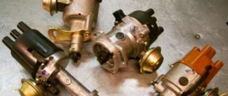
Repair and restoration of distributors of Japanese engines.
Distributor, also known as distributor, also known as ignition distributor, also known as ignition module.
In Japanese gasoline engine control systems, this is a technologically complex part that includes an electronic camshaft sensor, an electronic switch and a high-voltage ignition coil. The distributor is made as a single unit, it has its pros and cons. Unfortunately, the distributor is also sold as a single unit - this is a big, fat minus, because Currently, the cost of an “original” distributor at a dealer reaches 21,000-24,000 rubles.
Signs of distributor malfunction: Loss of engine power during acceleration; Unstable (“tweaking”) operation at idle; The engine is difficult to start and stalls when warming up; Popping noises in the intake or exhaust manifold during sudden acceleration; Engine computer memory contains a “misfire” error (loss of sparking) when scanning vehicles after 1996
Attention! You may be mistaken about the malfunction of your distributor. Similar symptoms are caused by other faulty components and components of the car. It would be more economically feasible for you to conduct electronic diagnostics and testing of the car’s ignition system
Contact us by phone: +7 495 9958674, +7 963 9777356 (Yuri), +7 495 7787546 (Alexander) or see the “contacts” page. You will receive maximum information, free consultation, and useful tips. The main reasons for distributor failure: Dirty engine injectors (look at the injectors); Old or “broken” spark plugs due to low-quality gasoline; Old, damaged or dirty high-voltage wires; “Lighting up” a car from a donor car with a faulty battery charging system; Dirty or cracked distributor cap; Oxidized, dirty battery terminals can also cause damage to the distributor. Malfunction of the generator and battery charging system.
Which distributor elements fail more often? According to our accumulated statistics - a switch and an ignition coil, and the probability of failure of both elements is the same - 50/50%. Repair of a distributor consists of replacing all its electronic components. Since the distributor body is quite reliable, we offer you the exchange of your faulty distributor for a restored one from our exchange stock. All distributors have been fully tested and tested on a special stand. We provide a guarantee on refurbished distributors. The components that we use when repairing distributors are only from original manufacturers, therefore reliable. When exchanging or repairing, we will definitely advise you so that you can avoid such troubles in the future. Services for dismantling, installing distributors, preventive cleaning of injectors and other related work can also be obtained from our “PAT auto” service center. In many stores, non-original Chinese-made distributors for Chrysler CIRRUS and Dodge STRATUS models with Mitsubishi 2.5L engines have appeared on sale. According to reviews from our clients and from our own experience, these “products,” unfortunately, do not justify their price (about 12,000 rubles). Upon careful examination, it turned out that the electronics of the switches are made of “consumer goods”, and the electrical insulation of the ignition coils is very weak. Our opinion is that such “miracle spare parts” are not intended for full and long-term work on these beautiful cars! In addition, they are usually not returnable to stores!
Attention! To help the diagnostician. We offer you reference books and other technical literature. You will have useful information with which you will be able to determine the causes of malfunctions and errors in the operation of components and assemblies of your car. Contents in Russian. Format - electronic books. OBDII codes Jeep GRAND CHEROKEE WJ 4.0L 1999-00
download demo >>>OBDII codes automatic transmission Chrysler 41TE (A604) 2001 download demo >>>OBDII codes automatic transmission Chrysler 41TE (A604) 2004 download demo >>>
We offer you reference books and other technical literature. You will have useful information with which you will be able to determine the causes of malfunctions and errors in the operation of components and assemblies of your car. Contents in Russian. Format - electronic books. OBDII codes Jeep GRAND CHEROKEE WJ 4.0L 1999-00. download demo >>>OBDII codes automatic transmission Chrysler 41TE (A604) 2001 download demo >>>OBDII codes automatic transmission Chrysler 41TE (A604) 2004 download demo >>>
PS Don't buy Chinese fakes.
What is electronic or contactless ignition?
The electronic or contactless ignition system is a more advanced version of the SZ for cars. The block of such a device is assembled from electronic elements. Contactless ignition on a VAZ is called that way, because in this case the circuit is closed and opened thanks to an electronic switch. The latter, in turn, operates from a transistor, and not from a distributor contact, as was before.
The electronic ignition circuit on a VAZ has minor differences depending on the type of engine - injector or carburetor. In any case, this option is in practice more modern, as a result of which its popularity among our compatriots is growing. Due to differences in the connection diagram and some differences for the injector and carburetor, some car owners believe that the BSZ and the electronic system are different components, but this is not so.
BSZ scheme for the domestic “seven”
Prerequisites for failure
Please note that the engine control system malfunction warning lamp, located on the device panel in the signaling unit, is the first indicator of deviations in the operation of the VAZ 2107, where an injector is used. Some modifications of the VAZ 2107 provide for the location of the warning lamp on the upper insert of the radio panel. By starting the ignition, a system malfunction is tested, which means the lamp lights up and goes out after the engine starts.
A prerequisite for diagnosing the ignition system is that the lamp does not go out when the engine is running.
By starting the ignition, a system malfunction is tested, which means the lamp lights up and goes out after the engine starts. A prerequisite for diagnosing the ignition system is that the lamp does not go out while the engine is running.
In situations where there is a malfunction, VAZ 2107 owners replace the spark plugs. Old factory spark plugs are usually replaced with iridium spark plugs from NGK or Denzo. Do not forget that only those spark plugs that are designed for the appropriate type of injection are suitable here.
The type of ignition system is no less important in determining the parameters of the spark plug. Often such manipulation does not provide much improvement (plugs have a fairly long service life), so the non-contact ignition system undergoes a full diagnosis.
Do you want to know more about how to install
valve timing according to marks on VAZ 2101-
VAZ 2107
? And so.
Why is it worth installing on “Seven”?
There are several reasons why you should install electronic ignition on a VAZ 2107.
Of course, it is important whether the engine is equipped with a carburetor or an injector, because the injection system does not have a distributor:
- If you install such an SZ, the car owner will no longer need to periodically service the contact group. That is, you can forget about oxidation and cleaning of contacts, as well as adjusting the gap.
- This VAZ 2107 ignition system is more reliable, since the contact group, which is most susceptible to breakdowns and wear, is simply absent.
- In this case, the spark will be distributed more evenly and stably throughout the engine cylinders, and this will not be affected by the performance of the power unit.
- The service life of the distributor as a whole increases as a result of the disappearance of vibration and shock of the axle in the case of the action of the so-called cams on the contacts.
- If the VAZ ignition timing is set and the system is configured correctly, and the engine operates in normal mode, there is a chance of saving gasoline. During normal operation of the internal combustion engine, its power can also be increased, especially since as a result of complete combustion of the mixture in the engine cylinders, there will be fewer harmful emissions.
- It will be easier to start the engine in cold weather, since the voltage level at the spark plugs will always be stable:
How to evaluate the work already done
Accurate diagnosis is carried out using a computer. However, it is also possible to independently assess how correctly the circuits are functioning.
- With the ignition off, check the contacts.
- Find out the voltage inside the module at terminals C and B.
- Check the high voltage wire. To do this, you need to take a candle and place it in the cap. In this case, it should be attached to the cylinder block. If the internal combustion engine is turned on using the starter, a spark will appear. The check is done for all wires. If a spark does not appear, then you need to check or even replace the entire ignition system.
- If the engine continues to operate incorrectly, the power system will need to be checked.
For the carburetor model VAZ 2110, marks are also set in order to regulate the ignition system.
If the ignition of the VAZ 2110 8-valve injector occurs early or, conversely, late, then the ergonomics of the entire engine deteriorates. Power also decreases. The engine is exposed to high temperatures and excessive loads. Among other things, detonation may occur. All this can lead to the VAZ 2110 losing ignition.
Repair and cleaning manual for the Lada 2110 carburetor, do-it-yourself steps for removing and installing the carburetor from the Lada 2111 car, instructions for disassembling and assembling parts of the Lada 2112 carburetor. Repair of the carburetor power system of the VAZ 2111, VAZ 2112, VAZ 2110. Maintenance of the engine of the Lada 2112 car. Instructions for repairing the cooling system, exhaust gas, power supply of Lada 2111. Features of the 8- and 16-valve engine of Lada 2110. Operation of the main components and assemblies of the engine
Installation Guide
How to install BSZ with your own hands on the “seven”? How to properly set and adjust the device? First you need to prepare everything you might need.
Tools and materials
To complete this task you will need:
- a set of keys;
- self-tapping screws;
- screwdriver set;
- construction drill.
Stages
Installation of electronic ignition must be carried out on a de-energized on-board network, otherwise a short circuit may occur in the system.
So disconnect the battery and then follow these steps:
- Disconnect all high-voltage wires from the spark plugs.
- Dismantle the distributor cover.
- After this, by rotating the crankshaft, it is necessary to set the slider to a position perpendicular to the axis of the power unit. Also mark the location on the middle mark of the distribution element scale, this will allow you to make adjustments without any problems in the future.
- The distributor fixing nut must be unscrewed, after which the device is dismantled.
- A non-contact regulator is installed instead of the dismantled distributor, while the slider and housing must be placed in the desired position in accordance with the previously established marks.
- The device cover is installed.
- Then you need to connect the high-voltage cables with the spark plugs.
- After completing these steps, you can replace the coil. In general, this task is quite simple, but when performing it, you should take into account the position of contacts B and K. If they are different on the new short circuit, then the element should be rotated relative to the fastener so that the contacts are located similar to the one that was installed previously.
- At the final stage of installation, the switch is installed; the best option would be to place it between the washer expansion tank and the headlight. The mechanism is fixed using self-tapping screws, and the so-called zero wiring should be brought out under one of them. As for the radiator, it should be leaned against the body.
Checking and adjusting the marks on the eight-valve injection valve
To adjust the ignition you will need the following tools:
- jack;
- wheel wrench;
- key (head) 10;
- key to 13;
- key to 17;
- key to 19;
- large slotted screwdriver;
- flashlight.
It is also advisable to involve an assistant.
Work order:
- We install the car on a horizontally flat surface. We block the rear wheels.
- Using a wheel wrench, unscrew the bolts securing the right wheel and jack it up. Unscrew the bolts completely and remove the wheel.
- Open the hood, use a 10 mm socket to unscrew the three bolts securing the front protective cover of the timing drive. Let's take it off.
- Using a 13mm wrench, loosen the generator belt tensioner nut and remove the belt.
- Using a 19mm wrench, unscrew the nut securing the generator pulley. To do this, you will need an assistant, whose task is to hold the brake pedal in the cabin when fifth gear is engaged. When all this is done, you will have the opportunity to see all the ignition marks of the VAZ-2110.
- We rotate the front wheel so that the lug on the camshaft gear clearly coincides with the protrusion on the rear timing drive cover. When they are aligned, take a flashlight and look at the position of the mark on the crankshaft pulley. It should point to the test point located on the oil pump cover. If they coincide, without letting go of the flashlight, we move to the engine compartment and compare the position of the marks on the flywheel crown. When the ignition is set correctly, it should also be aligned with the mark on the gearbox housing. In this case, everything is in order with the valve timing. The ignition marks are in their places. If, although the marks on the camshaft and the rear cover coincide, the tide on the crankshaft gear does not coincide with the point on the oil pump cover, it is necessary to make an adjustment.
- Using a 17 key, unscrew the timing belt tensioner pulley. We remove the belt.
- Without touching the timing shaft gears, rotate the wheel until the mark on the crankshaft pulley coincides with the marked point.
- We insert a slotted screwdriver into the inspection window so as to immobilize the flywheel.
- Carefully, so as not to change the settings, put the belt on the camshaft gear and crankshaft pulley. We tighten the tensioner pulley and fix it. Check to see if the marks have gone astray. If necessary, repeat the procedure.
Adjustment features
As for how to set the installed ignition unit on the “seven”, then, of course, this procedure is best carried out using special equipment. But since such installations can only be found in car repair shops, the adjustment procedure can be done by ear. Before you begin the process, you need to make sure that both the carburetor and the pump are operating normally. The process itself is performed as follows:
- First the engine warms up.
- Then the distributor fixing nut is unscrewed.
- The distributor itself should be slowly turned in different directions, while the motor should be running. The mechanism is turned until the operation of the internal combustion engine is smooth and the speed increases.
- After this, the fixing nut needs to be tightened.
- As for checking, to do this, you need to accelerate the car at third speed to about 50 km/h, then engage fourth gear and press the gas pedal. In this case, the sound of “fingers” or detonation should be heard from under the hood, which will last until the car’s speed increases by 5 km/h. If the sound continues longer, the distributor should be released and turned clockwise by about one degree. If you are unable to adjust the ignition yourself in this way, it is better to seek help from specialists - this procedure is inexpensive, but you will be sure that the engine will work normally.
Sorry, there are no surveys available at this time.
Checking the ignition angle while the vehicle is moving
It is best to check the functionality of the ignition system after any adjustments while driving. This is due to the design characteristics of the fuel dispenser and the octane number of the gasoline used. It happens that the ignition angles set according to the signs do not provide sufficient dynamics and throttle response. Adjusting the ear when detonation starts will help:
- We accelerate the car to a speed of 45-50 km/h on a flat section of the road;
- We turn on direct gear (on the fourth VAZ 2106) and fully press the accelerator pedal;
- A characteristic ringing sound (detonation) should appear, which will disappear after 2-3 seconds, and acceleration will be smooth and powerful without failures;
- If detonation does not disappear during the entire acceleration, the ignition angle is “early”;
- The complete absence of hum and slow dynamics indicate a delayed spark in the cylinders;
- We adjust the position of the distributor in place, turning it 3-5 degrees;
- When the adjustment is completed, the position of the distributor body relative to the block is marked with a line or paint.
Ignition adjustment work must be carried out regularly. The service interval for a simple contact ignition system is 15,000 km, for an electronic one – twice as long. The condition of spark plugs and high-voltage cables is also regularly checked. All installation operations are easy to do yourself; you don’t need a garage. The ability to independently repair the ignition of a VAZ 2106 is always useful on a long trip or in winter, when problems arise with starting.
Source