02/16/2022 6,172 Daewoo
Author: Ivan Baranov
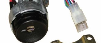
As you know, the ignition distributor or distributor is one of the main components in the ignition system of any car. If this unit fails, the driver will know about it in any case, since it will be impossible to start the engine. In this article we will tell you how to check the Matiz distributor and how to repair this device.
[Hide]
Ignition system of Daewoo Nexia with 8 valve engines
This ignition system, as stated above, is non-contact with a centrifugal distributor. That is, the system must necessarily consist of a distributor, a switch and an ignition coil. The distributor is attached to the cylinder head and connected to the camshaft. When purchasing parts for the distributor, I noticed that almost everywhere they sell a “Hall sensor” for distributors. The same statement is found on many sites on the Internet. But this statement is not true. An inductive sensor is installed in the distributor, that is, a coil on a magnetic circuit in the middle of which a permanent magnet rotates. In this case, an alternating voltage of approximately 3V is induced in the coil. This signal is fed to a switch, which converts the signal and, depending on it, controls the ignition coil. The switch is located inside the distributor.
I went through the distributor - it stopped starting (`97 Nexia GLE, 8kl.)
For clarity, I'll start from the beginning.
My Nexia twitched at idle and there were dips when picking up speed; in the dark, nothing seemed to spark under the hood, but I noticed that strong clicks were heard inside the distributor and at the same time the engine was jerking. After smoking a cigarette while looking at the forum at night, I found messages with the same symptoms, and this problem was solved at Topikstarter by replacing the distributor cap, slider and explosive wires. Well, without hesitation, I went and bought a cover and a slider (both originals) and went to install them on the car. Without removing the distributor, I unscrewed the cover, replaced the slider, fed the wires into the new cover and screwed it on. I try to start it - it barely starts and at the same time it jerks strongly, but before the replacement it started with half a turn and jerked almost imperceptibly. After working in convulsions for a couple of minutes, it stalled. I start it again - it jerks even more and immediately stalls. And since I read the forum for a long time, I decided that the “Hall sensor” was most likely to blame and I removed the distributor to replace it. Having completely disassembled the distributor, I changed the notorious sensor and, putting everything back together, I put the distributor in place. I'm trying to start it, the starter turns, but the engine doesn't even crank, it just spins as if there are no spark plugs in it. Please poke my nose at where and what I did wrong.
After repeated unsuccessful attempts to start it, I carried out the following checks: 1. I checked using the marks left in advance that the distributor was in the same position as before removal. 2. I removed the central explosive wire from the distributor, placed it next to some bolt on the body and turned the starter - it sparks strongly and regularly.
I couldn’t check the spark on the spark plugs because... there was no spark plug wrench at hand. I'll check today.
I have the following suspicions and questions: 1. Some of the new parts are faulty (cover, slider, sensor). Tell me how to check. 2. I may have installed the drive clutch incorrectly. Tell me how to check. Which side, smaller or larger, should face the same direction as the contact on the “slider”? 3. Is the distributor installed in its place only in the only correct position or are there any nuances? 4. I never paid any attention to it before, but now I noticed that while I was starting it, the “check engine” light was on. Is this how it should be or maybe this is the problem?
Source
Ignition system of Daewoo Nexia with a 16-valve engine.
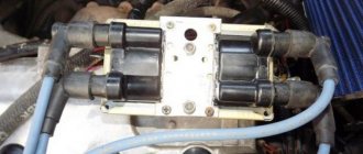
Unlike the ignition system, the 8-valve engine does not have a distributor. High voltage is generated by two ignition coils controlled by a two-channel switch, made in the same housing with the coils. This entire structure is called the ignition module. The distribution of high voltage in this case occurs by means of simultaneous supply of voltage in pairs to the cylinders. This system allows you to more accurately adjust the ignition timing depending on many factors.
Create an account or log in to comment
How I adjusted the ignition Everything is correct. I hear a rattling ringing sound during acceleration when the engine is running tight - is that them?
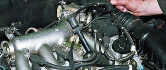
And where should the sound come from? This is neither bad nor good. Remove the distributor cap and slider.
Remove the distributor cover and slider. We see a slot on the shaft, which should be directed either up or down.
Using a 13mm wrench, loosen the distributor fixing bolts. Using a 13mm wrench, loosen the distributor mounting bolt and align the protrusions of the magnetic rotor with the protrusions of the stator.
Now all that remains is to combine the protrusions of the magnetic rotor with the positive stationary ebbs. Theoretically, the advance angle is set, but, making adjustments for gasoline, we turn the distributor another mm clockwise. Install the slider and cover.
Conclusion We check the correct installation while running.
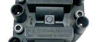
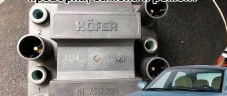
Ignition coils
The ignition coils used with both ignition systems are dry type. On a 16-valve engine, two coils are connected in one housing and have 4 terminals. Two of them are power supply (+ and -), and two are control ones from the ECU. The ignition coil of an 8-valve engine also has four terminals. The two terminals of the coil are connected to each other. One receives the plus from the ignition switch, and from the second the plus is supplied to the switch in the distributor. The remaining two wires suitable for the connectors connect the coil to the tachometer and the switch.
Create an account or log in to comment
How I adjusted the ignition Everything is correct. I hear a rattling ringing sound during acceleration when the engine is running tight - is that them?
And where should the sound come from? This is neither bad nor good. Remove the distributor cap and slider.
Remove the distributor cover and slider. We see a slot on the shaft, which should be directed either up or down.
Using a 13mm wrench, loosen the distributor fixing bolts. Using a 13mm wrench, loosen the distributor mounting bolt and align the protrusions of the magnetic rotor with the protrusions of the stator.
Now all that remains is to combine the protrusions of the magnetic rotor with the positive stationary ebbs. Theoretically, the advance angle is set, but, making adjustments for gasoline, we turn the distributor another mm clockwise. Install the slider and cover.
Conclusion We check the correct installation while running.
If there is no spark when starting the engine.
First, let's look at how to check for a spark. Modern ignition systems have a secondary voltage of about 25-32 kV; in early systems the voltage did not exceed 15 kV. The gap during testing should not exceed 10 mm; with a larger gap, the switch may fail. Reasons for the lack of spark on a 16-valve engine, as on most modern injection engines. You can read in detail in the article “Injection engine does not start.”
Troubleshooting on an 8-valve engine is somewhat different and first of all you need to check the presence of power on the positive wire of the distributor and the integrity of the control wire from the distributor to the coil. The most loaded part of the ignition system is the switch and it is also the cause of the malfunction in most cases. It is quite difficult to check it; for this you will need a stand that simulates the operation of the ignition system, or an oscilloscope. Usually it is simply replaced with a known good one. The ignition coil fails extremely rarely, but for some reason, when searching for a lost spark, it is the first to be replaced. Checking the coil is quite simple; you need to measure the resistance of the windings. The measurement value of the primary winding is approximately 0.4-0.6 Ohm, and the secondary winding is about 8.3-8.5 kOhm. When measuring, it is worth taking into account the magnitude of the instrument error. The most common malfunction is a break in the secondary winding, in which case the resistance value will differ significantly from the nominal value.
Diagnosis of distributor cover faults and their elimination
The distributor is a unique mechanism designed to determine the moment when high-voltage pulses begin to form in the ignition system. This device is used to distribute electric ignition among the cylinders of two types of gasoline internal combustion engines - injection and carburetor. The distributor, by its nature, differs from other components in that its structure has a fairly large number of parts that wear out quickly. But the condition of this mechanism has a direct impact on the efficiency of the engine, as well as its starting characteristics. In addition, how efficiently the distributor works also affects the overall dynamics of the car and the toxicity of the exhaust.
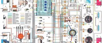
Electrical diagram of Daewoo Nexia
The Daewoo Nexia electrical circuit diagram of which is presented in this section was not developed yesterday, and this greatly facilitates the repair of the main components of the car. The design of the car as a whole repeats the Opel Cadet of the 80s. Minor changes have been made to decorative elements and optics, and there are also options with a twin-shaft 16-valve engine, which in no way affected the electrical diagram that we posted below.
As you can see, the scheme is simple and to some extent identical to VAZ cars, and those who are familiar with the old Cadet will understand it without any difficulty.
Design Features
The one and a half liter single-shaft in-line petrol engine G15MF was created before the advent of Euro-2 standards, so the design feature is an extremely simple exhaust tract design without a catalyst and CO probe. The remaining nuances of the internal combustion engine are:
- modernization of the injection system - injection here is distributed, but simultaneous, regulated by a potentiometer, as on domestic Ladas;
- modification of the combustion chambers - these engines have a smaller cylinder diameter compared to the prototype, and a dome-shaped chamber, partially extended into the piston;
- according to the manufacturer, oil consumption is within 300 g/1000 km, and gasoline consumption is 8.8 l/100 km in the combined cycle;
- flat tooth timing belt from the leading brand Geitz with a service life of 200,000 km, although the safety of the valves is already ensured here, they cannot meet the pistons.
Timing belt G15MF
The gas distribution system is made according to the SOHC scheme with one camshaft. Compared to the sample, the volumes of the combustion chambers are reduced; power will be increased only in the next series of Daewoo engines - A15MF.
To increase the resource, the attachment is driven by a separate belt, the condition of which is recommended to be monitored every 20 thousand km, and changed after 50 thousand.
After the introduction of Euro-3 and even Euro-4 regulations, Daewoo management continued to install these obsolete power drives on Nexia and Espero until 2008. Compactly located attachments do not interfere with major repairs, including on your own.
Nexia fuse box
As in all European cars of those times, the Nexia has a fuse block with fork-type fuses. This is much more convenient than the old cartridge elements. Each fuse is responsible for a specific section of the circuit. In the event of an overload or short circuit, the fuse does not allow harm to electrical equipment located in the circuit after it. The basic rule, which cannot be neglected, is that any use of jumpers that short-circuit the contacts tightly, or bugs, is unacceptable. It is also unacceptable to use fuses that do not correspond to the rating. If the fuse has a resistance lower than the rated value, it will blow, and if it is significantly higher, it will burn out the equipment that it was supposed to protect.
For ease of use, fuses have housings of different colors. 10 amp fuses have a red body, 20 amp yellow, 30 amp fuses have a green body. The fuse board is located in the same housing as the relay block, and the entire mounting block is located on the driver's side under the instrument panel.
Problems with power windows
The build quality of the Daewoo Nexia, unfortunately, very much depends on the factory at which the car was assembled. Most often, problems with window regulators arise on Russian-assembled Daewoos, and the components supplied to both Uzbekistan and Poland are, apparently, exactly the same. However, if problems arise with the window regulators, you need to make sure that the problem is in the electrical part. If everything is fine with the mechanics, then you should check the fuse in the mounting block.
If everything is in order with it, then most likely it is in the lift control unit. The main unit is located in the driver's door armrest. The most likely failure is failure of the control keys or lack of contact in the control unit. The fact is that the door is constantly subject to vibration, so due to poor quality assembly, the contacts may simply come off.
The procedure for connecting high-voltage wires on a Daewoo Nexia car
visibility
67220
archive
0
Attention!!! Emergency Note! For you, Nexia waters and Nexia lovers. If under the hood of your iron friend there is a four-cylinder, eight-valve engine with a volume of 1.5 L - G15MF with the good old ignition distributor (distributor), then this article will be useful to you.
And it is especially useful for those happy owners of Daewoo Nexia cars who like to change high-voltage wires and spark plugs themselves. And it does it very quickly. So quickly that he forgets to remember in what order the high-voltage (HV) wires are connected to the ignition distributor ))).
Common situation? And naturally, in such a situation, the busybody starts calling a car mechanic he knows. He talks about the embarrassment that happened to him and asks for help over the phone.
Or (this option seems more likely to me), using the same smartphone, but to “access” the Internet, typing phrases (questions) into a search engine like – “ The procedure for connecting high-voltage wires Nexia ”, “ In what order are high-voltage wires connected to distributor (ignition distributor) on the 8 valve Nexia ?” or “ Wiring diagram for armored wires on Nexia with a distributor ” - in the hope of quickly sorting out the problem. And... And of course he finds the necessary information on the blog page “Auto Repair School”))). At the very least, I hope so!
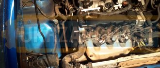
Now to the point. The order of connecting high-voltage wires on an 8-valve Daewoo Nexia (Daewoo Nexia) with an ignition distributor (distributor) is 1-3-4-2 . The report is carried out from the contact for the wire of the first cylinder, counterclockwise.
We recommend: Installing a generator on Niva 2121
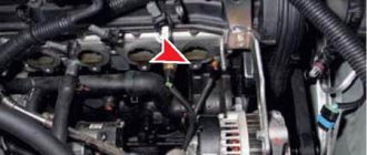
All that remains is to determine which contact of the distributor cover the wire of the 1st cylinder is connected to. the arrow on the distributor body (ignition distributor) (photo 1). Found it? Here, this arrow points to the contact for the wire of the first cylinder. Then everything is simple - look at photos number 2 and 3.
The high voltage wire from the ignition coil is connected to the contact located in the center of the distributor cap.
A small addition, so that there are no misunderstandings: on the Daewoo Nexia engine, the cylinder counting order is carried out according to the most common principle, from left to right, from the timing belt (photo 4).
This is all! I think you will no longer have problems connecting high-voltage (armor) wires))). For yourself, you can, and probably even need to, number the contacts on the distributor cover with a marker.
So that in the future, when replacing wires, you don’t waste time and rummage through the farthest corners of your brain in search of the numbers you once memorized.
Since, over a certain period of time, a person’s memory can “get lost or erased somewhere” the numbers in the order of connecting high-voltage wires - 1-3-4-2 . But numbers or marks left by a marker will be much more difficult to erase.
When using an article or photographs, an active direct hyperlink to the website www.avtorem.info is required!
Air conditioning Daewoo Nexia
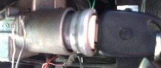
Some Nexia cars were equipped with air conditioning. It was included in the most expensive configurations and worked quite reliably with proper maintenance and operation. The main reasons for the failure of the air conditioner, which relate to electrical equipment, were failures of the electromechanical clutch of the compressor drive and breakdowns of the climate control system. Despite the fairly reliable design of the air conditioner itself, there were annoying errors when assembling components, which sometimes led to premature wear of the compressor and evaporator.
Since the operation of the air conditioner is connected to the heating and blowing system, it could not help but respond to frequent failures of the air circulation drive motor. The engine itself cannot be repaired, but before you say goodbye to it, it’s worth checking the circuit right down to the fuses. If there is voltage on the circuit after the fuse, it is quite possible that the contacts in the motor power supply are to blame.
Checking the fuel pump
You can check the operation of the fuel pump yourself; it is not difficult to do. After gaining access to the fuel pump, you can begin to diagnose it. On command, the assistant turns on the ignition (for a couple of seconds), after which a sound should appear indicating that the pump is working.
If the fuel pump does not emit “signs of life,” then it is either faulty or requires complete replacement. There are situations when both the pump and the starter are both functioning, but the engine does not start. Then, using a multimeter, you need to check whether voltage is coming to the submersible element. This is done as follows. After turning the ignition key, you must hold it in the on position for three seconds, and if current flows to the pump, the tester will definitely show this.
In addition, it will be necessary to check the resistance of the fuel supply element to the engine. If at the moment of starting the engine you do not hear any signs of its operation, this must be done. To do this, connect the multimeter to the power contacts of the fuel pump. After diagnosis, resistance measurements must be compared with the manufacturer's data. If the figures obtained differ greatly from the manufacturer's specifications, then most likely the fuel pump has completely failed.
Ignition system
The contactless ignition system of the Daewoo Nexia works stably and there are no outright complaints about it. In the event that all elements are serviced and checked for mechanical integrity in a timely manner. First of all, this applies to highly loaded devices:
- ignition distributor;
- coils;
- high voltage circuit;
- electronic control unit.
Since 2008, an ECU without feedback has been installed on the car, so its operation has become more stable. In addition to all other corrective functions, the ECU also controls the operation of the ignition system. The control unit adjusts the operation of the system based on the following data:
- crankshaft rotation speed;
- throttle opening angle;
- data from the catalytic converter oxygen sensor;
- temperature and pressure of incoming air.
The ignition system must quickly respond to ECU signals and make adjustments to the advance angle. In case of any abnormal readings, the system informs the driver about the need for maintenance or repair.
Thus, any faults in the electrical equipment of the Daewoo Nexia can be localized, and the diagram posted on the page will help with this. Control the on-board voltage, and have a good trip!
Source
How to check the device for serviceability?
The distributor diagnostic procedure is carried out as follows:
- First, you need to look at the engine in the dark to see if there are sparks in the distributor area. If there is, then this indicates a violation of the insulation. Remember to always keep the lid dry.
- Also diagnose the integrity of the wiring - whether the contacts are intact or not. The terminals themselves on the cover must not be removed.
- Remove the cover and diagnose the integrity of the slider. After removal, look at the inside of the cover to see if the contacts are intact.
- Try shaking the slider - any gaps are eliminated. If there is play, there will be an unstable gap in the contacts.
- Diagnose the wear and gap in the contacts - it should be no more than 2 mm, the less the gap, the better. If the contacts are burnt, they must be cleaned.
- Then connect the lamp to the side terminal of the distributor and turn on the ignition. Try turning the engine manually - at this time the lamp should blink and go out at regular intervals. If this does not happen, then most likely there is a short circuit in the system, as a rule, this is due to the fact that the moving part touches the housing itself (the author of the video about diagnosing the distributor cap at home is Auto Electrics HF).