VAZ 2108, 2109, 21099 cars with a carburetor engine are equipped with a fuel tank ventilation system.
It is part of the power supply system. The ventilation system of the gas tank is necessary to prevent the occurrence of excess pressure in it, which is created by the fuel vapors generated here (especially at high temperatures in the summer or when the car is strongly rocked while driving).
Operating principle of the gas tank ventilation system
Through two drainage tubes located in the fuel tank, fuel vapors, which create excess pressure in the tank, enter the separator through a hose. They condense in it, and the resulting gasoline flows back into the fuel tank. Fuel vapor is removed through a two-way valve connected by a hose to the separator.
Installation of the fuel tank ventilation system for VAZ 2108, 2109, 21099
Elements of the fuel tank ventilation system for VAZ 2108, 2109, 21099 cars
— Drainage tubes inside the tank
Two drain tubes are inserted into one another, their ends are located at the edges of the fuel tank to prevent fuel from leaking out when the car turns. They have a common outlet to the drain hose to the separator.
— Gasoline vapor separator
A sealed plastic tank installed in the rear right side of the car on a bracket. Connected by hoses to the fuel tank and a two-way check valve. Serves to condense fuel vapors entering it from the tank. Capacity 7 liters. The gasoline condensate from the separator is drained back into the fuel tank, and the vapors are released into the atmosphere through a two-way valve.
— Two-way check valve
Located near the fuel tank filler neck. Connected by a hose to the separator. Double-acting check valve: it introduces atmospheric air into the gas tank and, when the pressure of fuel vapors in it increases, releases them into the atmosphere.
Malfunctions of the gas tank ventilation system
— Breakdown of the two-way check valve
The result of a valve failure or clogged hoses will be that the pressure in the tank exceeds the norm, which can lead to its deformation, damage to the hoses and separator. As a result, a fuel leak may occur and a persistent smell of gasoline may appear both in and around the car.
Notes and additions
— On the injection engine 2111 of VAZ 21083, 21093, 21099 cars, instead of a fuel tank ventilation system, there is a fuel vapor recovery system. It is similar to the ventilation system, but in addition it has an adsorber with a valve that absorbs fuel vapors and, at the command of the control unit (purge of the adsorber), sends them back to the engine for afterburning. This allows you not to release toxic fumes into the atmosphere and comply with certain toxicity standards.
Gas tank vapor recovery system
In almost every modern car, the gas tank has a built-in ventilation system (otherwise called a vapor recovery system).
It includes elements such as:
- separator;
- connecting tubes;
- two way valve.
The main purpose of this system is to maintain stable pressure inside the tank and capture vapors formed in it during strong shaking, vibration, or in hot weather, when the fuel inside begins to expand and evaporate. The absence of such ventilation could lead to the fact that the gas tank, under the influence of excess vapor pressure, would simply swell and become deformed.
The fuel vapor recovery system operates as follows:
- when heated or vibrating, gasoline vapors are formed in the tank;
- due to their volatility, they rise up and fall inside two drainage tubes running from the tank to the separator;
- getting inside the separator, they condense, turning into drops of liquid, and flow back into the gas tank;
- excess vapors that do not have time to condense (for example, in very hot weather) enter the two-way valve from the separator and are discharged into the atmosphere.
In cars with an injector, the tank ventilation system works on a similar principle with the only difference that instead of a two-way valve, it has an adsorber (absorber) of vapors installed, which accumulates them and, at the command of the ECU, releases them into the engine for afterburning. This avoids intentional leakage of fuel into the environment.
Description of the power system design
The vehicle's power system is designed to store fuel reserves, purify fuel and air from foreign impurities, and supply air and fuel to the engine cylinders.
The air entering the engine cylinders is cleaned of dust by an air filter. Air filter
installed in the engine compartment on three rubber supports. The filter element is replaceable and made of special paper. To prevent contaminated air from leaking into the intake tract, there is a sealing edging at the top of the element. To replace the filter element, the filter cover is removable. The purified air passes through the mass air flow sensor through the air duct to the throttle valve.
Throttle valve
regulates the amount of air entering the engine cylinders. The damper drive from the gas pedal is cable. The damper rotates on an axis in the housing (pipe). The throttle body is secured to the receiver flange with studs. The housing has a channel for coolant. The channel is connected to the cooling system by rubber hoses. Circulating coolant through the throttle body prevents the body's internal air cavities from freezing in the winter. The housing contains fittings for connection to the absorber and the engine crankcase ventilation system.
The throttle body, with the throttle position sensor and idle speed control installed on it, form the throttle assembly.
Throttle assembly:
1 - throttle valve drive sector; 2, 4 — fittings for connection to the engine cooling system; 3 — crankcase gas outlet fitting; 5 — throttle position sensor; 6 — idle speed regulator; 7 — fitting for connecting to the adsorber; 8 — throttle valve; 9 — throttle body pipe
Air is supplied to the intake valves of the engine cylinders through the receiver and the intake manifold.
Fuel tank
steel, welded from two stamped parts. The tank is suspended from the bottom of the car on two steel clamps. The filler neck of the fuel tank is located on the right side of the vehicle and is closed with a plug. Fuel from the tank is supplied by an electric submersible fuel pump.
The pump is installed in the fuel tank. To access the pump, there is a hatch with a cover in the bottom of the car under the rear seat cushion. A strainer is installed on the inlet pipe of the fuel pump, which traps small solid particles of debris that enter the fuel tank along with gasoline. The pump is turned on by command from the ECU.
Fuel pump:
1 — protrusion for fastening the mesh filter; 2 — fuel intake pipe for connecting a strainer; 3 - body; 4 — electrical connector block; 5 - outlet (discharge) pipe for connection to the fuel module cover with a corrugated tube
From the pump, through the corrugated tube of the fuel module (see below), gasoline enters the fuel line and then into the fuel filter, where the fuel undergoes more thorough cleaning.
The fuel filter is made of paper, installed in a non-separable metal housing. The purified fuel flows through the fuel line into the fuel rail.
Engine fuel filter 11183 (1.6i):
1 — inlet pipe; 2 - body; 3 — fuel flow direction arrow (painted on the filter housing); 4 - outlet pipe
Note. The fuel filter of the 2111 (1.5i) engine has threaded connecting pipes.
The fuel rail holds four injectors and supplies fuel to them. The connection between the ramp and the injectors is sealed with rubber rings.
The fuel pressure regulator is a bypass valve that maintains in the system (fuel line) the operating pressure necessary for proper operation of the injection system.
All cars of recent years of production are equipped with a fuel vapor recovery system (in accordance with EURO II environmental requirements), where the above-fuel space of the tank is connected to the atmosphere not directly, but through the elements of this system. The system consists of a separator, safety valve, adsorber, gravity valve, adsorber purge valve, check valve, connecting pipes and hoses. The separator and gravity valve are mounted under the right rear fender of the vehicle. In the separator, gasoline vapors are partially condensed and returned back to the fuel tank. The gravity valve prevents fuel from leaking out of the tank when the vehicle turns over. The safety (two-way) valve prevents the formation of excess pressure of fuel vapor in the tank, as well as the occurrence of vacuum there caused by fuel consumption.
Location of elements of the fuel vapor recovery system in the rear of the vehicle:
1 - safety valve; 2 - separator; 3 — plug of the filler neck of the fuel tank; 4 - gravity valve
Note. The photo shows the rear bumper.
From the separator, non-condensed gasoline vapors flow through tubes and connecting hoses into the adsorber, which prevents the vapors from entering the atmosphere. An adsorber is a container where gasoline vapors are absorbed by activated carbon. When the engine is running at high crankshaft speed, the ECU sends a signal to open the canister purge valve, and gasoline vapors are sucked into the intake module receiver.
Adsorber:
1 — adsorber body; 2 - pipe for connecting the internal cavity of the adsorber with the atmosphere; 3 — adsorber purge valve; 4 — valve connecting pipe; 5 — adsorber connecting pipe
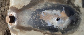
Separator design
The VAZ 2114 gasoline vapor separator is a small, completely sealed tank made of metal or impact-resistant plastic. It is installed in the right rear part of the car on a special bracket. Using a hose system, it is connected to the gas tank (from where vapors flow through drain pipes) and to a two-way valve. The total volume of this device is 7 liters.
Once in this tank, the vapors accumulate in it and, due to increased concentration and cooling, condense. Drops of condensation settle on the walls and bottom, after which they gradually flow back into the gas tank. The same vapors that did not have time to condense flow towards the two-way valve. From its name it is easy to guess that it works in both directions at once - “for the intake” of atmospheric air into the tank and “for the release” of fuel vapors outside.
Despite the obvious simplicity of the fuel ventilation system and the minimum of parts located in it, it still breaks down, leading to rather unpleasant consequences.
So, signs of a vapor separator failure may include:
- smell of fuel inside the cabin;
- the smell of fuel near the car (and a lot of time has passed since refueling);
- gasoline stains near the neck of the tank;
- drops of fuel on the ground after a long stay.
Having noticed these signs, we can conclude that the VAZ 2114 gas tank separator is cracked or leaky and is no longer doing its job.
Features of the engine power system 11183 (1.6i)
Receiver
engine 11183 (1.6i) is made of plastic.
Engine Intake Module 11183 (1.6i):
1 — flange with an o-ring for fastening the throttle pipe; 2 - receiver with o-rings for connection to the inlet pipeline
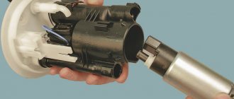
Engine Fuel Module 11183 (1.6i):
1 — inlet pipe (for supplying fuel to the pressure regulator); 2 - outlet (discharge) pipe; 3 — module cover; 4 — fuel level indicator sensor; 5 - intake chamber; 6 — module cover guide
Fuel pump
combined with a fuel level indicator sensor and a fuel pressure regulator into a single unit -
a fuel module
(often called an electric fuel pump). Fuel from the pump (through the outlet pipe of the fuel module) enters the fuel filter. Purified gasoline is again supplied through the fuel line and through a tee to the inlet pipe of the fuel module, and then supplied to the fuel rail.
Engine fuel pressure regulator 11183 (1.6i):
1 — hole for dumping excess fuel; 2, 4 — sealing rings; 3 — holes for supplying fuel to the regulator; 5 — body; 6 - terminal for connecting the regulator to ground
Fuel rail for engine 11183 (1.6i) complete with injectors:
1 — diagnostic fitting; 2 - fuel rail; 3 — fitting for connecting to the fuel line; 4, 5, 6 and 7 - injectors
Excess fuel is released through the pressure regulator into the tank. The fuel pressure regulator is installed in the fuel module cover.
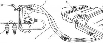
Engine power supply diagram 11183 (1.6i):
1 - nozzle; 2 - fuel rail; 3 — diagnostic fitting; 4 - adsorber; 5 - check valve; 6 — throttle assembly; 7 - gravity valve; 8 — safety (two-way) valve; 9 - separator; 10 — fuel line tubes connecting the fuel module to the fuel filter; 11 — fuel module; 12 — fuel filter; 13 - filler pipe; 14 — fuel tank; 15 — fuel line connecting the fuel module to the fuel rail; 16 — metal fuel pipe; 17 — connecting hose; 16 - fitting for connecting the fuel rail to the fuel line
Source
Separator replacement
Due to the fact that the separator is an ordinary tank (most often plastic), it is hardly worth trying to repair it with improvised means - due to the high fluidity of gasoline, the problem may remain, and time for repairs will be wasted. That is why the best option in this situation is replacement (especially since a new vapor separator is very inexpensive).
If possible, it is better to purchase a metal separator - it is more resistant to vibrations and has an increased service life.
To replace this device you will need the following set of tools:
- Phillips screwdriver;
- key to 8;
- key to 10;
- ratchet;
- head at 13.
The separator replacement itself is performed in the following order:
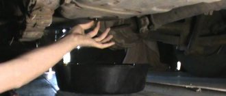
- Place the machine on a pit or overpass.
- Apply the handbrake.
- Remove the rear bumper trim.
- Fold back the right side of the upholstery inside the trunk.
- Using a 10mm wrench, unscrew the separator shield fixing nut.
- Remove the fuel tank cap.
- Using a screwdriver, loosen the clamp where the inlet hose connects to the pipe at the bottom of the car.
- Remove the hose from the filler tube.
- Using a 13mm socket, unscrew the nut securing the clamp that presses the filler tube to the body.
- Using the same head, unscrew the fasteners of the filler pipe bracket.
- Loosen the clamp holding the gas tank ventilation hose to the filler tube fitting.
- Remove the ventilation system hose from the fitting.
- Remove the filling tube from the separator.
- Remove the O-ring from the junction of the separator shield and the tube.
- Unscrew the bolt securing the separator shield to the car body (you will need a size 8 wrench).
- Move the separator shield and separator to the side.
- Loosen the clamp securing the separator hose.
- Remove the separator hose from the fitting.
- Remove the old separator.
The new gas tank vapor separator should be installed in exactly the same order, but in reverse order.
Source
Replacing the gas tank yourself
The main reason why you have to remove the gas tank on VAZ 2110, 2111 and 2112 cars is its damage, after which further operation is impossible. If the tank is leaking, then the leak can be eliminated only by completely removing it, soldering the fuel passage areas, or replacing the gas tank assembly.
In order to perform this procedure, you will need the following tool:
- Head for 10, 8 and 13 mm
- Screwdrivers with both flat and Phillips blades
- Key 17 (for old-style cars with a 1.5 liter engine)
- Penetrating lubricant
- Ratchet handles or cranks
- Extension Cords
Filler valve 2114
- To the beginning of the forum
- Forum Rules
- Old design
- FAQ
- Search
- Users
I park the car on a slight slope - the front is higher, the back is lower, and also tilted towards the gas tank filler neck.
Zilch when opening the lid = clogged tank ventilation! (As far as I understand)
When you open the gas cap there is only a slight whine.
Someone asked at the beginning of the summer)