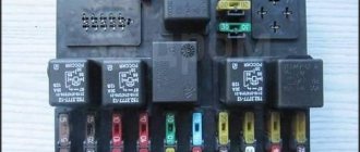
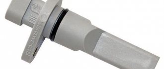
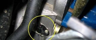
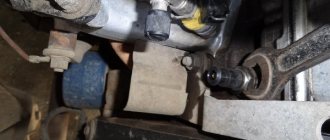
If there are no speedometer readings on your VAZ 2114, you check the fuses and then accurately diagnose a breakdown of the speed sensor. In this case, unstable idling or sluggish response to the accelerator pedal sends the car owner to diagnose engine sensors. And the reason may not be in them at all. Although the speed sensor on the VAZ 2114 is located in the manual transmission, it may be the culprit of problems that are not related to the gearbox.
This small sensor does more than just count the vehicle's mileage and determine its instantaneous speed.
Its data is used by the electronic engine control unit. The following engine parameters are adjusted using the speedometer sensor:
- idle speed: the ECU compares the crankshaft speed with the actual speed of the car;
- correct formation of the proportion of the fuel-air mixture;
- engine power at the current time;
- fuel consumption, especially when coasting: when the throttle is closed and the speed is fixed, fuel does not flow to the injectors.
How the sensor measures speed
The speed sensor works according to Hall principles. In simple terms, its work is to convert the Hall voltage into pulses that are transmitted to the controller. The speed of a car is calculated using impulses. For 1 km of track, the sensor produces 6004 pulses, counting the intervals between pulses, the DS and determines the speed.
Information from the sensor is transmitted to the ECU (the “brains” of the car), as well as the speedometer and IAC (idle air control). If the sensor does not work correctly, the readings on the car's speedometer may differ from the real ones.
Design and principle of operation
Three generations of speed sensors were installed on injection engines of the tenth VAZ family.
- Electromechanical with a cable stretched to the speedometer. The torque was transmitted through a gear drive from the gearbox. The most capricious option in operation and unreliable in indications.
- Electromechanical without cable. The rotation transmission was still gear-based, the electrical signal was transmitted through wires.
Both of these sensors transmitted output shaft speed using complex mechanics that often failed.
- The third generation received a reliable and unpretentious Hall circuit, in which mechanical parts were kept to a minimum. Therefore, the reliability of the device was higher by default.
Let's look at this design in more detail.
The Hall effect is that when a concentrated electric field passes through a magnetic field, an electrical impulse occurs. To “materialize” it, a semiconductor is placed in a magnetic field, at the ends of which a completely measurable voltage appears. This impulse is the same signal that is sent to the electronic speedometer and engine control unit. The speed sensor connection diagram clearly demonstrates the principle of operation of the speed sensor on a VAZ 2114 car.
As you can see, the signal goes not only to the speedometer unit.
In accordance with the operating principle of the Hall system, one revolution of the sensor shaft generates one electrical pulse. At the same time, there are no unnecessary mechanics: only the input shaft of the device connected to the output shaft of the manual transmission.
How impulses are converted into speed and mileage
There is a known quantity: the circumference of a car tire. Of course, this system works correctly only when installing standard tires and normal tire pressure. The ECU and sensor controller take readings and convert them into mileage. That is, the odometer has already received its share of information. Divide this value by time - we get the speed of movement.
Signs of a malfunctioning speed sensor
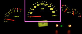
If the sensor is not working correctly or is faulty, what is shown on the speedometer will differ from the real ones. If the sensor does not function at all, the speedometer needle will “lie” at zero. In addition, the idle may be unstable, which is why the speed may “jump”.
If, while driving, you find that the needle on the speedometer hangs in one place, shows the wrong speed, or even lies down, it’s time to check the sensor and identify the malfunction.
Functions
It is incorrect to assume that the DS serves solely to transmit information regarding the current speed of the vehicle. In fact, this device has several tasks.
- Transferring information to the dashboard, namely the speedometer, about the speed of the car.
- Supports optimal functioning of the idle air control.
- Transferring data to the electronic control unit in order to maintain optimal speed depending on the travel mode.
The DS is connected to the speedometer and controller using a mounting block located in the engine compartment. And inside the car, directly on the heater fan relay, there is a sensor fuse.
Errors and symptoms
If the device starts to work incorrectly or breaks down, you should pay attention to the on-board computer screen. Diagnostics of errors will determine that the DS has stopped functioning properly and measures should be taken to eliminate the breakdown
| Error code | What does it mean |
| P0500 | This error indicates that the computer does not receive a signal from the speed sensor. |
| P0503 | This error code informs about the receipt of an unstable signal from the DS, which is intermittent. |
If these error codes appear on the dashboard, you should definitely inspect the electrical circuit for oxidation or damage to the integrity of the contacts. Often it is because of this that the DS stops transmitting information.
But there are other signs by which you can determine that the DS is out of order:
- On the dashboard, the speedometer shows incorrect speed data or the needle does not move at all;
- With a slight acceleration, the speed floats, the engine switches off on its own;
- Fuel consumption increases;
- Engine power is noticeably reduced.
These signs may be signals of problems with other systems. But if you find one of the characteristic signs of a DS failure, plus one of two error codes appears on the on-board computer, then the problem lies precisely in the speed sensor.
Functionality check
Do not rush to replace the device until you are sure that the faulty sensor is the culprit of the problem.
The check is performed in several ways. Decide for yourself which one you prefer.
Checking the operation of the DS
Before doing this, be sure to check the condition of the wiring and contacts. If they are oxidized or rusted, or there are breaks in the circuit, then the DS itself may well be operational. You just need to return the wiring and contacts to a functional state. If the check shows that everything is intact and there are no problems with the contacts, then diagnose the speed sensor.
- If you don’t want to remove the DS, then place the car on a level surface, secure it with blocks and lift the left front wheel with a jack. Connect the voltmeter to the contacts of the sensor and begin to rotate the wheel with your hands. At the same time, look at the voltmeter data. If the voltage increases with frequency in proportion to the increase in wheel speed, the DS operates normally.
- Another method also does not require removing the measuring device. But for this you will need a test lamp. Use a jack to lift the left front wheel and connect the test lamp to the DC contacts. After this, manually rotate the wheel. If the lamp lights up, the sensor is working well.
- The third method involves dismantling the sensor and then checking the input and output voltage. The device for measuring the indicators will be a voltmeter.
- The fourth method is actively used by those who prefer to repair their car with their own hands. Here you have to check the sensor drive. To do this, lift the wheel using a jack and remove the sensor. Feel for the DS drive, and then begin to rotate the wheel. You can feel with your fingers that the drive rotates. If there are no jams, everything rotates evenly, then the drive is in good condition.
If a malfunction of the DS is detected, the only correct solution is to remove it and replace it with a new sensor.
Having determined that your DS has already served its purpose, you can begin the replacement procedure.
How to determine a faulty speed sensor
If you have an on-board computer installed, it will display the DS error:
- Error P0500 indicates that the ECU does not receive speed information from the sensor
- Error P0503 indicates that the signal from the sensor is intermittent or intermittent
In the first case, there is a high probability of a malfunction of the sensor itself, but in the second, with error P0503, the sensor may be working, but the problem lies in broken wires or problems in the block suitable for the sensor. When the above errors appear on the BC or the speedometer recumbent needle, we diagnose not only the sensor but also the entire circuit.
Replacing DS with VAZ 2114
The part can be replaced at home. The work can be performed by a person who does not have specialized knowledge and experience. Replacement is carried out in the following sequence:
- Turn off the on-board power supply voltage. To do this, remove the negative terminal from the battery.
- Remove the corrugation. This is necessary for unhindered access to the sensor.
- Disconnect the electrical connector. The plug is equipped with two latches that prevent spontaneous disconnection.
- Unscrew the device counterclockwise.
Installation of the new part must be carried out in reverse order. In some cases, the sensor drive may need to be replaced at the same time as the sensor.
Which sensor is needed for replacement?
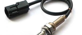
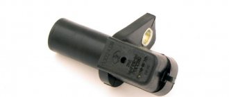
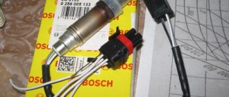
From the factory, the VAZ 2114 is equipped with a sensor marked 2111-3843010 , article number: 343.3843. The sensor is manufactured in the city of Kursk. Its cost at the moment is from 230 rubles and above. In addition to this, analogue sensors are offered:
- Fenox SS10102O7 price from 200 rub (Belarus)
- Manover MR21123843 price from 270 RUR (Germany)
When choosing a sensor, we recommend installing exactly the one supplied by AvtoVAZ from the factory. Although it is not uncommon for it to fail at 50–70 thousand km. One of the common causes of sensor failure is water getting inside. After which rust forms on the sensor rod and it jams.
Purpose
Let us immediately note that the task of this sensor includes several functions.
It is intended:
- To supply an electronic signal to the speedometer installed on the dashboard, resulting in the ability to control the speed of movement and the distance traveled;
- Based on the readings of this sensor, the electronic unit adjusts and sets optimal speed in different modes of movement;
- The sensor signals influence the operation of the idle speed sensor.
Instructions for removing and replacing the sensor
So, to get to the DS, you need to remove either the adsorber or the air filter housing. It is better to go one way and remove the adsorber, which is secured with 2 bolts.
Disconnect the positive terminal from the battery and unscrew the two nuts securing the adsorber, then lift it up and move it to the side.
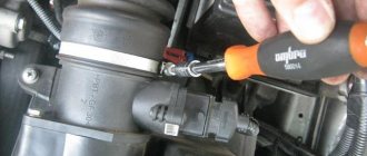
The speed sensor will be located at the top of the gearbox next to the dipstick. Disconnect the terminal from the sensor and unscrew it by hand. If you tighten it too much, you will need a 21 wrench.
Having unscrewed the old sensor, we carry out all the necessary diagnostics described below, and reassemble in the reverse order.
The test showed a negative result - the unit will have to be changed
To remove and install, you will need one tool: a 22mm wrench. The nut should be unscrewed with caution: the thread may become stuck due to unfavorable operating conditions. The VAZ 2114 speed sensor is replaced after cleaning the “seat” on the gearbox housing. Be sure to check the condition of the wire insulation and the integrity of the connector. Buy a branded sensor from a trusted supplier.
Before connecting the connector, it is necessary to lubricate the contacts with electrical compound. This will protect the contacts from corrosion for a long time. Be sure to secure the signal cable so that it does not fray due to vibration.
Diagnostics of the speed sensor and the entire circuit
Checking for broken wiring
So, to find the cause of the malfunction, it is necessary to check both the speed sensor and the entire circuit as a whole. To do this, disconnect the block with 3 wires from the sensor and visually inspect it. A block with three wires - power, signal and ground. If all the wires are in order, we proceed to further inspection.
Checking the sensor drive
Next, we check the sensor drive that comes out of the gearbox. Let's jack up any front wheel of the car and start turning it, while looking at the sensor drive itself. It should spin easily without jamming or crunching. You can touch it with your finger to determine whether it is spinning or not. If everything is in order with the drive, we move on to further diagnostics. If not, the drive will need to be replaced.
Checking for an open circuit
Now, using a tester or a multimeter, let’s check whether power is supplied to the sensor block. We check with a screwdriver with an indicator. We hook one end to the + battery with the other into connector No. 3, turn on the ignition, look, the light should be on. Then we check the power supply, one end to the (-) battery, the other to connector No. 1, turn on the ignition, look, the light should be on. We put the sensor in place, check the signal one, connect one end to the battery power supply, the other to the signal one on sensor No. 2, spin the wheel, preferably quickly, the light should blink.
If after all diagnostic procedures no problems are identified, there is no open circuit, the sensor drive on the box is normal, then the sensor should be replaced.
Speedometer sensor location
Regardless of the year of manufacture of the car, this device is installed on the gearbox housing .
It is attached to the drive using a threaded connection. To find this sensor you need to look at the gearbox in the area of the right CV joint . Next, you should find a part with a connected electrical connector. Below is a photo of where the VAZ 2114 speedometer sensor is located. On older models, a cable is attached to the device. It is necessary to transmit torque to a mechanical speedometer.
Design
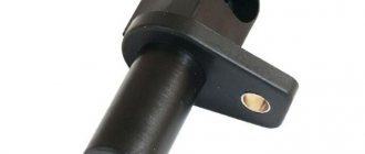
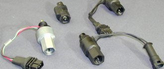
The speed sensor is made of plastic, inside of which there is an electrical circuit that converts mechanical energy into electrical impulses transmitted to the ECU.
The sensor has an internal thread, thanks to which it is installed on the speedometer drive. The DSA transmits impulses through wires, so it has a special connector that connects to the car's wiring, and then to the ECU.
Inside the sensor there is a special plastic shaft, which is installed in the speedometer drive and then rotates the electrical part inside the sensor. Quite often, this shaft is cut off, which leads to damage to the sensor, after which the sensor cannot be repaired, but only replaced with a new one.
Examination
Checking the sensor is quite simple, since it consists only of an external inspection of the part; as a rule, the reasons why a given part fails are mainly mechanical, which are quite easy to notice.
To check the sensor, it must be dismantled and inspected; it should not contain:
- Wire breaks;
- Damage to insulation;
- Cracks on the body;
- The shaft must have an exact geometric shape;
If the sensor has any damage, it must be replaced.

