Using inexpensive and widespread integrated circuits TDA1557, TDA1558, you can assemble a simple low-frequency power amplifier that requires a minimum number of external components.
The amplifier on this chip was previously widely used in car radios. From an old car radio that has long since outlived its usefulness, you can unsolder or even cut out a full-fledged power amplifier with a section of the board.
It can be adapted to amplify the sound of a computer, laptop, DVD and various types of set-top boxes.
TDA1557Q, TDA1558Q - monolithic class B integrated amplifier in a plastic case.
| Parameter | min. meaning | Max. meaning |
| Supply voltage, V | 6 | 18 |
| Current consumption in pause mode, mA | 100mA | |
| Maximum crystal temperature, C | ||
| Gain, dB | 45 | 47 |
| Bias voltage, mV | 250 | |
| Channel separation, dB | -40 | |
| Gain difference between channels | 1dB | |
| Distortion factor at output power up to 12W | 0,5% | |
| Output power, THD 10%, 4 Ohm, W | 22 | |
| Peak current consumption, A | up to 4 | |
| Critical crystal temperature, Celsius | 150 | |
| Channel separation no less than, dB | 40 | |
| Gain difference between channels no more than, dB | 1 | |
| Frequency response unevenness in the frequency range 25-20000 Hz no more, dB | 1 | |
| Duration of soldering one terminal with solder 300-350 C no more than, sec | 3 |
Block diagram of the TDA1557Q chip
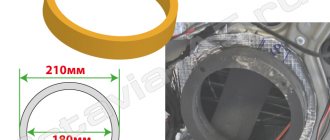
Dimensions TDA1557Q
Typical connection diagram TDA1557Q
Schematic diagram of switching on TDA1557 with switch-on delay
A delay chain of 100kOhm, 1kOhm resistors and a 100.0x16V capacitor turn on the amplifier with a delay to eliminate clicks in speaker systems.
Typical wiring diagram TDA1557
Amplifier PCB
DIY simple amplifier based on TDA1558Q
Safety precautions when connecting the device
When installing a subwoofer and amplifier, you must adhere to the following rules:
- Before starting work, disconnect the battery. It should be remembered that turning off the power may lead to incorrect operation of the airbags. Some types of stock radios require a code when turned on again. It is allowed to de-energize the circuits to which the connection is made by removing the fuse.
- The connection of the wires must be reliable and protected from external influences. The best option is soldering followed by protecting the joint with insulating tape, corrugated pipe or heat shrink.
- Use high-quality wiring with the appropriate cross-section. The event ensures operational safety and improves sound quality.
- The power supply circuit is protected by a separate fuse of the appropriate rating. It is prohibited to use standard fuse-links designed for other current values. Information about the voltage in the power circuit is available in the documentation for the device.
- Additional equipment must be securely fixed and not move when the vehicle moves.
Compliance with safety measures during installation will allow you to operate the speaker systems without the risk of fire or damage to the vehicle.
Block diagram of the TDA1557Q chip
Amplifier installation on TDA 1558Q
If the assembly can be done by surface mounting without using a printed circuit board, then first you need to remove unused pins 4, 9 and 15 from the microcircuit. Then carefully straighten the pins. Next, bend pins 5, 13 and 14 up, all these pins are connected to the power positive. The next step is to bend pins 3, 7 and 11 down - this is the power supply minus, or “ground”. After these manipulations, screw the chip to the heat sink using thermal conductive paste. The pictures show the installation from different angles, but I will still explain. Pins 1 and 2 are soldered together - this is the input of the right channel, a 0.33 µF capacitor must be soldered to them. The same must be done with pins 16 and 17. The common wire for the input is the minus power supply or ground. Solder the power plus wire to pins 5, 13 and 14. The same wire is soldered to the positive of the 6800 uF capacitor. Pins 3, 7 and 11 bent down are also soldered together with a wire, and this wire is soldered to the minus of the 6800 uF capacitor. Next, the wires go from the capacitor to the power source. Pins 6 and 8 are the output of the right channel, pin 6 is soldered to the plus of the speaker, and pin 8 to the minus. Pins 10 and 12 are the output of the left channel, pin 10 is soldered to the plus of the speaker, and pin 12 to the minus. The 0.22 µF capacitor must be soldered parallel to the terminals of the 6800 µF capacitor.
Options for assembled amplifiers
The microcircuits have a fairly high output power (about 22W x 2) and to cool it you will need a radiator with an area of at least 100 sq. cm. You can use a radiator from the processor.
Before applying power, carefully check the installation for correct installation. At the input of the amplifier you need to install a dual variable resistor 47-100 kOhm to adjust the volume.
The above diagrams are for beginner radio amateurs, they are quite easy to assemble and do not need to be configured. Assembled using cheap parts that can be bought at any radio store. Parts can also be found in car radios.
- Refinement of the amplifier "Radio engineering U-101-stereo"
- Rated output power at a load of 8 ohms, W ... 25
- Harmonic coefficient, %, no more than ……………….. 0.003
- Output voltage slew rate, V/µs…. at least 40
- Rated input voltage, V……………….. 0.7 More details…
- Active speaker system.
- Antenna Amplifiers - SWA
Many people still have “Radiotekhnika U-101-stereo” power amplifiers from Soviet times. The article below discusses its diagram, characteristics and modifications.
MZF with low nonlinear distortions
Main technical characteristics:
Everyone likes mini-music centers, they have a wide range of functionality, good characteristics, and take up little space in the apartment. One bad thing is that the output power is low, usually no more than 5-10W. Of course, you can buy a more powerful device, but a music center with an output power of about 100W costs an order of magnitude more. And this is essential for the pockets of many of our citizens. Read more…
In the article published here, our regular author analyzes the circuitry of Polish-made antenna amplifiers and justifies his informed approach to their selection in terms of noise and gain factors.
He also gives recommendations for repairing such devices, which quite often fail from lightning discharges, and eliminating self-excitation.
This will, we hope, allow many radio amateurs not only to choose the necessary amplifier, but also to improve its performance. Read more…
Popularity: 55,904 views.
Amplifier based on TDA1562Q chip 70W
12/08/2014 | DIY, Electro | 1 | Kirill
As a child, I assembled an interesting amplifier on the TDA1562Q; it was interesting due to its minimal set of parts, simplicity and good performance, as well as high output power. The 70W power declared by the manufacturer is not RMS, i.e.
This power cannot be supplied constantly, only at peak moments.
This is due to the fact that the voltage on the microcircuit is pumped up by high-capacity capacitors, thanks to which the TDA1562Q amplifier is capable of increasing the power in situ than similar amplifiers without capacitor pumping.
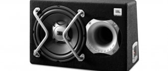
The amplifier on the TDA1562Q was assembled specifically for a homemade subwoofer, the heart of which was a 10″ (inch) Sony Xplod low-frequency head, despite the overestimated speaker power declared by the manufacturer, the TDA1562Q microcircuits pumped it VERY well, so much so that in a 10 m² room, it pumped bass and chest and cabinets.
The subwoofer died in a fire, but the amplifier was left, torn apart in search of the necessary parts. And now, I decided to bring it back to life and repeat the successful experience of assembling Basszilla.
Let's go back to restoring the amplifier on the TDA1562Q :
The connection circuit and printed circuit board are borrowed from the NM2034 kit for assembling a LF amplifier 70W, mono (TDA1562Q, auto)
I didn't want to invent a wheel.
— Nesterov Kirill
The ratings of electronic components are given in the table:
| Position | Name | Note | Col. |
| C1 | 0.47uF/63V | Type K73-17 | 1 |
| S2, NW | ODmkF or 0.22 μF | Type K73-44 (film) (code 104 or 224) | 2 |
| C4 | 10uF/25…50V | 1 | |
| C5, C6 | 4700uF/25V | 0 17 | 2 |
| C7 | ODmkF | (104) | 1 |
| C8 | 2200uF/25V | 1 | |
| DA1 | TDA1562 | 1 | |
| HL1 | LED, red. 03 mm | 1 | |
| HL2 | LED, green, 03 mm | 1 | |
| R1 | 1 OkOhm | Trimmer resistor | 1 |
| R2, R4 | 1 OkOhm | Brown, black, orange | 2 |
| R3 | 1 OOOhm or 91 kOhm | Brown, black, yellow or white, brown, orange | 1 |
| R5 | 1kOhm | Brown, black, red | 1 |
| R 6 | 820 Ohm | Grey, red, brown | 1 |
| VD1 | Zeiiner 2V7 | Zener diode 2.7 V 1/2W | 1 |
| VT1 | BC558 | Possible replacement for BC557 | 1 |
| VT2 | BC547 | Possible replacement for BC548 | 1 |
| PLS-40 | 2 pins3 pins | 2 2 | |
| Removable jumper | 1 | ||
| A2034 | PCB 67×37 | 1 |
There are many printed circuit boards for TDA1562Q amplifiers on the Internet, but I liked this one due to the presence of LED overload indication and convenient arrangement of parts. The amplifier is good for a beginner, easy to assemble and does not require any settings other than a variable resistor.
Radio amplifier circuit, amplifier circuit for subwoofer and others
DIY 60W sound amplifier
DIY 60W sound amplifier
While there is some time, another brand new circuit appears on the site, we all know that the greater the power of the amplifier, the more expensive it is. But what can you do if you need an amplifier that is both powerful and at the same time not too expensive?
I would like to present to many a familiar circuit of a 25 or 60 watt permanent amplifier, the cost of which is pennies. As already mentioned, the power of the amplifier depends on the supply voltage and resistor values (60-watt values are indicated in parentheses).
Active subwoofer
The active subwoofer is equipped with a built-in amplifier installed in the same housing as the speaker. On the outside of the case there are potentiometers for smooth adjustment of volume or frequency parameters. Thanks to the controls, the user can configure the device in accordance with the sound parameters of the other speakers in the speaker system.
Main characteristics of active subwoofers
Active devices include, for example, the Mystery MSK-12.3 subwoofer, which has the following parameters:
- speaker diameter - 300 mm;
- power in normal mode - 280 W;
- peak power value - 560 W;
- frequency range - from 28 Hz to 2900 Hz;
- sensitivity - 90 dB;
- The Mystery MK-2.80 amplifier is included in the package.
Advantages and disadvantages
Pros of an active subwoofer:
- Possibility of saving space, since the amplifier is located in the same acoustic housing with the speaker.
- Due to the built-in amplifier, the subwoofer has an expanded range of uses.
- The subwoofer housing has separate outputs for installing standard speakers. Thanks to this, a separate acoustic system can be built based on the active device.
- Various body shapes.
- degraded sound parameters;
- the amplifier and device may overheat;
- amplifier power limitation;
- relatively high cost of devices;
- active devices are equipped with simplified housings.
We make an amplifier for a subwoofer with our own hands - 3 stages of assembly on the TDA1562Q integrated circuit
Any driver loves to listen to good music in his car. This entertainment lifts your spirits and helps you easily endure a long traffic jam. It is much more pleasant to perceive high-quality sound, and poor sound spoils the impression of listening to your favorite song.
Many motorists prefer louder music with good bass. A subwoofer can create the desired effect, but it requires an amplifier to function.
It is quite possible to make an amplifier for a subwoofer with your own hands, but before doing so, it is better to carefully read the recommendations.
To assemble a subwoofer amplifier with your own hands correctly, you need to stock up on free time and patience. You won't need to spend a lot of money. First of all, you need to purchase a power amplifier made on an integrated circuit. Next, we will look at how to assemble a subwoofer amplifier with your own hands based on the TDA1562Q chip.
Amplifier circuit diagram
Below is a schematic diagram of the amplifier.
This circuit, in addition to the power amplifier, has a preamplifier made on a dual operational amplifier chip, which also plays the role of a frequency filter.
When powered by a car battery, the maximum output power of the amplifier will be about 50 W, which is quite enough to “drive” an average subwoofer.
Required equipment and components
So, in addition to the above microcircuit, we will need:
- operational amplifier TL 072 (can be replaced with TL 062, TL 082 or 4558 microcircuits);
- resistors with a power of 0.25-0.5 W;
- electrolytic capacitors (new!);
- non-polar capacitors - film;
- insulated wires;
- thermal paste;
- radiator with a dispersion area of at least 600 cm²;
- single-sided PCB sheet.
It is also recommended that the circuit be powered through a 10 A fuse and a choke, which can be “borrowed” from an old radio.
Of course, we can’t do without a soldering iron, solder and some skill in handling all this.
Installation
Main amplifier board
The amplifier circuit board diagram is shown below.
A printed circuit board can be made by etching a PCB with a copper substrate with a ferric chloride solution. It is easier to transfer the pattern of the contact tracks onto the board from a glossy sheet of paper on which this pattern is printed using a laser printer. The nuances of this method can easily be found on the Internet on relevant electrical engineering sites.
We solder the parts carefully, removing excess flux. This is especially true for microcircuits. The op-amp chip can be installed via the eight-pin panel.
The amplifier chip is installed on the heat sink. It must have an area of more than 600 cm². The role of a radiator can be performed by a car chassis.
After installing all the elements, connect the wires.
Power stabilization and communication unit
In the circuit described above, we used the simplest circuit for powering the amplifier through a battery, however, for more stable operation of the amplifier, you can connect it through a stabilizer. You can assemble this device yourself (a circuit for every taste can be found very easily on the Internet), but the easiest way is to use a ready-made stabilization unit from an old amplifier or buy a new one.
In addition, the stabilization unit allows you to save car battery power.
Discharge is prevented by a relay with a separate REM terminal, operating under a voltage of 12 V. The terminal is installed at the output of the car radio, thanks to which the subwoofer begins to work together with the music device.
To control the operation of the amplifier, you can install an LED in the power supply circuit of the device.
Final assembly of the device
After mounting the board, we complete the final assembly of the amplifier and place it in the housing. The body can be made independently from ordinary plywood using a jigsaw. A diagram of the required dimensions is drawn on plywood, cut out with a jigsaw and secured with sealant.
This is interesting: How to make the rear bumper of a UAZ Hunter yourself
- You can also purchase the case in a store or use an aluminum box, which will simultaneously act as a radiator.
- When placing all the parts in the case, you need to ensure free air circulation in it for better cooling of the parts.
- The amplifier housing must be securely fastened in the car.
- Before installation, it is important to make sure that the power polarity is correct, otherwise the device will immediately burn out.
Functionality check
We figured out how to make an amplifier for a subwoofer, all that remains is to check its performance. This can be done at home, but in no case should you neglect safety rules, otherwise you may get an electric shock or damage the device. Testing is carried out as follows: the amplifier is powered through a battery and a speaker with a resistance of 20 ohms is connected. A load is applied to the amplifier and the power is checked.
If you do not have basic knowledge of radio electronics, it is better to check the functionality by installing the amplifier in the speaker system. Before this, the radio is configured. If, after installing the amplifier into the system, you get the desired sound, then the amplifier is assembled correctly.
Conclusion
Installing an amplifier yourself has many advantages:
- High quality sound.
- High output power.
- Fairly simple assembly process.
- Saving money.
If you decide to build the amplifier yourself, take it seriously, read the exact description of the process and try to understand the essence. It is important to follow safety precautions while working.
The installation of each part must be done very carefully and carefully; there is no need to rush here, otherwise all the work will be in vain.
Check all contacts so that you don’t have to do this after installation in the audio system.
This description is suitable for beginners who have never encountered working with electronics. Making an amplifier with your own hands will allow you to significantly save on the purchase of this expensive device. Proper assembly can guarantee reliable operation and high-quality sound.
What to do if you want to do everything from scratch
If you want to mount everything in a unique housing or use old passive acoustics for this purpose, you will definitely need a power amplifier
. If there is an old one lying around somewhere, the issue can be considered resolved. Those who don’t have anything suitable at hand will have to improvise a little. The ideal place where you can find everything is the well-known AliExpress. Here you will find both integrated circuits that are inexpensive and can provide high output power per channel, as well as standard products that can be adapted to solve the task at hand - creating a music center.
Many car enthusiasts have probably thought about using a car radio at home, in the country or in the garage in order to be able to listen to music not only in the car. Several questions arise: is it possible to do this and how to connect the car radio at home yourself?
A good radio usually costs much less than any music center, and with multi-channel outputs, it becomes possible to assemble a full-fledged home theater. Which will have decent sound quality for a modest amount, but you will still need to devote a little of your time to this moment.
Amplifier with filter for subwoofer - simple circuit
The thing we are going to talk about now, as is clear from the title of the article, is a homemade amplifier for a subwoofer, popularly called a “Sub”. The device has an active low-pass filter built on operational amplifiers and a combiner that provides signal input from the stereo output.
Since the signal for the circuit is taken from the speaker outputs, there is no need to interfere with the operating amplifier. Receiving the signal from the speakers has another advantage, namely, it allows you to maintain a constant volume ratio of the subwoofer to the stereo system.
Naturally, the subwoofer channel gain can be adjusted using a potentiometer. After filtering out high frequencies and highlighting low frequencies (20-150 Hz), the audio signal is amplified using the TDA2030 or TDA2040, TDA2050 chip. This allows you to customize the bass output to your liking. Any woofer with more than 50 watts of power per subwoofer will work successfully in this project.
Filter circuit with UMZCH subwoofer
Schematic diagram of low-pass filter and UMZF subwoofer
Description of the operation of the amplifier circuit
The stereo signal is fed to the In connector via C1 (100nF) and R1 (2.2M) on the first channel and C2 (100nF) and R2 (2.2M) on the other channel. It is then fed to the input of op-amp U1A (TL074).
Potentiometer P1 (220k), operating in the feedback circuit of amplifier U1A, adjusts the gain of the entire system. Next, the signal is fed to a second-order filter with elements U1B (TL074), R3 (68k), R4 (150k), C3 (22nF) and C4 (4.7 nF), which works as a Butterworth filter.
Through circuit C5 (220nF), R5 (100k), the signal is supplied to repeater U1C, and then through C6 (10uF) to the input of amplifier U2 (TDA2030).
Capacitor C6 ensures separation of the DC component of the preamplifier signal from the power amplifier. Resistors R7 (100k), R8 (100k) and R9 (100k) serve to polarize the amplifier input, and capacitor C7 (22uF) filters the offset voltage. Elements R10 (4.7 k), R11 (150 k) and C8 (2.
2 uF) operate in a negative feedback loop and have the task of forming the spectral characteristics of the amplifier. Resistor R12 (1R) together with capacitor C9 (100nF) form the output characteristic.
Capacitor C10 (2200uF) prevents DC current from passing through the speaker and, together with the speaker resistance, determines the lower cutoff frequency of the entire amplifier.
Useful: Do-it-yourself electric cigarette lighter
Protection diodes D1 (1N4007) and D2 (1N4007) prevent voltage surges that may occur in the speaker coil. The supply voltage, in the range of 18-30 V, is supplied to the Zas connector, capacitor C11 (1000 - 4700uF) is the main filter capacitor (do not skimp on its capacity).
Regulator U3 (78L15) together with capacitors C12 (100nF), C15 (100uF) and C16 (100nF) provides a 15 V supply voltage to the U1 chip.
Elements R13 (10k), R14 (10k) and capacitors C13 (100uF), C14 (100nF) form a voltage divider for operational amplifiers, forming half of the supply voltage.
Subwoofer assembly
The entire system is soldered onto a printed circuit board. Installation should begin by soldering two jumpers. The installation order of the remaining elements is any. At the very end, capacitor C11 should be soldered in because it must be installed lying down (the legs need to be bent accordingly).
Printed circuit board for the device
The input signal must be connected to the In connector using twisted wires (twisted pair). The U2 chip must be equipped with a large radiator.
The circuit should be powered from a transformer through a diode bridge rectifier; the filter capacitor is already on the board. The transformer should have a secondary voltage in the range of 16 - 20 V, but after rectification it should not exceed 30 V. A subwoofer with good parameters should be connected to the output - a lot depends on the head.
DIY home subwoofer amplifier
2– 5,00 Loading…
CLICK HERE AND OPEN COMMENTS
Description of devices
The term subwoofer refers to an acoustic speaker or system capable of reproducing sound waves in the frequency range of 20-120 Hz. The work is based on the principle of converting electrical signals from an amplifier into sound. For this, an electromechanical device is used - a speaker, which has a special design that ensures the generation of low-frequency sound signals. To improve the sound, it is installed in a housing with a strictly defined volume. Parts of the housing and speaker suspension should not create extraneous sounds (creaking).
Design features of subwoofers
There are several designs for installing the speaker:
- Open speaker installation or unrestricted acoustic baffle. The element is placed on a box with a large volume. On a car, a similar box is the luggage compartment in cars with a sedan body type.
- Installation in a small closed box. The dimensions of the box impose restrictions on the frequency ranges, cutting off the very bottom.
- Bass reflex housing. In such a device, a channel is used that has certain overall dimensions. The bass reflex is based on the effect of the meeting of waves emitted by the outer and inner sides of the speaker.
- A strip body, which is a bass reflex with an additional bulkhead. The speaker is located inside, on the partition. The sound is transmitted through the bass reflex hole. The design is used to create small-sized devices with improved sound parameters.
- The housing of a passive radiator, which is a combination of active and passive speakers with identical characteristics. The elements operate in antiphase. Due to the distance and dimensions, which are calculated individually for each device, it is possible to obtain clear sound with a low frequency.
Amplifier on tda1562
Amplifier on tda1562
The proposed power amplifier is built on the TDA1562 chip, which implements the new “H” class. Its essence is that up to a certain power value the amplifier operates in class “B”. If the output Power increases further, the voltage boost circuit in the output stage is activated and thus allows the amplifier to be driven to maximum power.
The TDA1562 amplifier circuit shows a ULF version with a power supply for use at home. A transformer with an overall power of 150 W must provide a secondary winding current of at least 6 A.
Ready-made trans units from TVs - TS180 lamps - are suitable. It is better to assemble the diode bridge on D242 - D245. To operate the TDA1562 amplifier in a car, we simply supply power directly from a 12 V battery to the chip. Don't forget about the radiator, at least 300 square meters.
The amplifier has output protection against short circuit and thermal protection.
Specifications of the amplifier on TDA1562
Upit……………………………………………………………+8…18 V
Iconsumption (Uin.=0)……………………………………. 0.15…0.2 A Iconst. average…………………………………….. 1.5…2 A Icons. Maksim………………………………………. up to 10 A Rout. nominal (RMS)…………….50 W (4 Ohm); 30 W (8 Ohm) Pout. maximum …………………..70 W (4 Ohm.) ; 40 W (8 Ohm.) frab………………………………………….15…60000 Hz (+0 dB; -3dB) Uin. ………………………………………………… -0.7 V Kusil……………………………………………………………..26 dB Kgarm. ………………………………………………………….0.03% Ksignal/noise………………………………………………………. -90 dB Damper. (100 Hz; 4 Ohm) ……………………..not less than 40
The Masterkit company has been producing ready-made kits for its assembly for a long time, so those who don’t want to bother with manufacturing can order:
Thanks to internal voltage booster elements and 10,000 uF capacitors, it is possible to develop a power of up to 100 W at a 4 Ohm load with a power supply of 16 volts.
Real tests of the amplifier on the TDA1562 showed a considerable level of nonlinear distortion, so it is recommended to install this circuit specifically as a subwoofer, where the criticality of SOI is not so important, and not for the left - right mid-high frequency channels.
In stationary conditions, to increase the output power, it is better to power the amplifier chip on the TDA1562 from a voltage increased to 17V.
Discuss on the FORUM
Inspection and troubleshooting of the power supply.
If you purchased a new power supply, then you can safely skip this point.
Turn on the computer power supply to check the output voltage. Make sure that when current is applied, the cooler (fan) installed on the rear starts spinning.
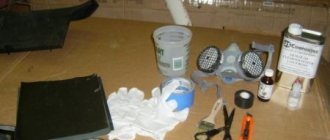
Open the lid and look inside the unit, there will probably be a lot of dust there, wipe everything thoroughly with a dry cloth, you can also use a vacuum cleaner. After cleaning off dirt and dust, carefully inspect the board contacts for defects and cracks in the solder.
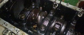
We carefully inspect the capacitors located
on the board, if they are swollen, this indicates that the block is faulty, or it does not have long to live. (capacitors are circled in red in the picture above) Swollen capacitors must be replaced
This process requires caution, since high-voltage capacitors contain a residual current charge, which can cause a slight but very noticeable electric shock. Assemble the power supply and start connecting