A possible reason for your power windows, cigarette lighter, or other electrical device not working may be a blown fuse or broken relay.
Below - about fuses and relays on the LADA Kalina (station wagon, hatchback) of the 2nd generation: where they are, how the circuits are deciphered and how to replace them yourself.
Where are the fuses on Kalina and why are they needed?
Every vehicle is equipped with a fuse box. The first generation “Kalina” is equipped with 3 such devices: installation, control and additional. The second generation model, or as it is also called “Kalina 2”, is equipped with 2 blocks.
These elements are necessary not only to protect all vehicle electronics from combustion, but also prevent the occurrence of fire, because In the event of a short circuit, they take on the entire load. In this case, the fuse itself fails, thereby stopping the flow of current to the electrical appliance.
Or maybe it's not the fan relay?
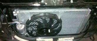
In order to accurately determine the cause of such a malfunction, it is necessary first of all to check all fan contacts for the presence of oxides and traces of rust, as well as the wiring for breaks and abrasions.
Fan relay and fuse, where are they?
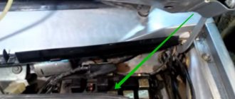
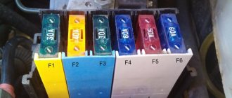
The additional fuse box is marked with an arrow in the photo.
If these manipulations did not bring any success, then it is necessary to look at the fuse and relay responsible for the operation of the cooling fan.
- Finding them is not difficult; you just need to unscrew one bolt located on the side of the center console near the left foot of the front passenger.
- When the decorative trim is dismantled, we will need a “10” key to remove the fuse box from its place of fixation and bring it out.
- This work may cause some inconvenience, because thick wire harnesses are connected to the relay block.
- This is how it looks after removal, now all that remains is to check their functionality and put everything back in the reverse order.
When they are dismantled from their place, you can easily carry out work on them.
- Low speed cooling fan relay.
- Main relay.
- High speed cooling fan relay.
- 50 Amp fuse.
- Relay for turning on the pump (fuel).
Source
Fuse types
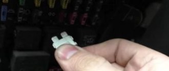
Fuses are classified into cylindrical and blade. The first ones were used in the operation of old-style Russian cars. Knife-type elements are considered safer, more convenient and are used in all Lada Kalina cars.
Fuses also differ in the rated current indicated on the housing and in size. In addition, each value of the maximum permissible current has its own color, which also makes it possible to distinguish fuses without much difficulty.
Problems when paying with bank cards
Sometimes difficulties may arise when paying with Visa/MasterCard bank cards. The most common of them:
- There is a restriction on the card for paying for online purchases
- A plastic card is not intended for making payments online.
- The plastic card is not activated for making payments online.
- There are not enough funds on the plastic card.
In order to solve these problems, you need to call or write to the technical support of the bank where you are served. Bank specialists will help you resolve them and make payments.
That's basically it. The entire process of paying for a book in PDF format on car repair on our website takes 1-2 minutes.
Mounting block
Located under the instrument panel for controlling dimensions and headlights, on the driver's side to the left of the steering wheel. In this block, Kalina fuses are responsible for the safety of almost all installed electrical appliances. The location of the mounting block for car fuses of generations 1 and 2 is the same, but its diagram is different.
A breakdown of the Kalina fuses of the 1st and 2nd generations is presented below.
Description
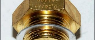
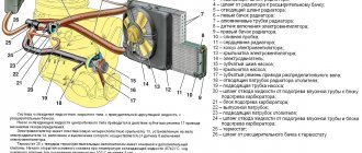
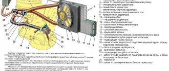
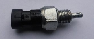
It is known that every Priora and Kalina has a cooling system that ensures normal engine operation and prevents it from overheating. One of the cooling devices of the unit is a fan sensor, the signal from which activates the ventilation device.
In Kalinas devices, this controller is designed so that it turns on the fan when the engine temperature reaches a certain point. Thanks to the fan, which must turn on according to a signal from the controller, the engine temperature will always be normal and will not exceed the permissible threshold. If the device does not work, the fan does not turn on, and the engine may overheat.
Sensor connection diagram in the cooling system
Control block
On the 1st generation Kalina it is installed under a cover in the center console. The fuses in this unit protect the most basic electronics. There is also a connector for injector diagnostics. On a 2nd generation car the unit is located under the hood, in the engine compartment.
Removal and replacement process
To replace blown fuses and broken relays, you will need plastic tweezers or needle-nose pliers/long-nose pliers.
Under the hood
The procedure is as follows:
- Turn off the ignition and open the hood.
- Remove the cover from the unit by pulling it up.
- Pull out the required fuse and insert a new one.
- Check the operation of the protected device. If the fuse link immediately burns out, you need to find and eliminate the cause of the short circuit.
- Close the block with a lid.
Decoding the fuses on Kalina 1
Mounting block fuses
| Marking on the diagram | Current strength, A | Protected elements of the electrical network |
| F-1 | 10 | Turn signals, reverse signal, immobilizer, instrument panel |
| F-2 | 30 | Electric door windows |
| F-3 | 10 | Emergency Signal |
| F-4 | 20 | Windshield wipers and washer, turning off heated rear view glass |
| F-5 | 25 | Interior heater engine (heater) |
| F-6 | 20 | Sound signal (beep) |
| F-7 | 10 | Car interior lights, brake lights |
| F-8 | 20 | Heated rear view glass |
| F-9 | 5 | Right dimensions, glove compartment lamp |
| F-10 | 5 | Left dimensions, external rear license plate illumination |
| F-11 | 7,5 | Rear fog lights |
| F-12 | 7,5 | Right low beam, low beam position control for right headlight |
| F-13 | 7,5 | Left low beam, low beam lamp position corrector for left headlight |
| F-14 | 10 | Right high beam |
| F-15 | 10 | Left high beam |
| F-16 | 10 | Right front fog lights |
| F-17 | 10 | Left front fog lights |
| F-18 | 15 | Seat heating |
| F-19 | 10 | ABS brake system |
| F-20 | 15 | Cigarette lighter |
| F-21 | 10 | Reverse fuse "Kalina" (limiter on the gearbox) |
| F-22 | 15 | Security alarm |
| F-23, F-24, F-25 | Stock | |
| F-26 | 25 | ABS |
| F-27 | 50 | Electric power steering |
| F-28 | 50 | ABS |
How to check DVV yourself
A situation may arise when the sensor is triggered “every time”. To make sure it works, they use a home-grown method for checking the DVV. Proceed as follows:
- The sensor is suspended on a suitable cord or insulated wire.
- The two contacts of the sensor are connected to a multimeter in resistance measurement mode.
- The tip of the part is lowered into an electric kettle with cold water. The initial reading of the device should be 4.5 kOhm.
- The kettle is turned on. As the temperature increases, the resistance value will decrease sharply.
- Before the water boils, the sensor resistance will be 177 ohms. If there is a discrepancy with the actual readings, the DVV must be replaced.
"Kalina 2" - decoding the purpose of the fuses
Mounting block fuses on Kalina 2
| Designation on the diagram | Current strength, A | Protected elements of the electrical network |
| F-1 | 15 | Ignition coil, injectors, engine control unit (ECU, “brains”), engine cooling fan |
| F-2 | 25 | Body electrical equipment, power windows, exterior mirrors |
| F-3 | 15 | Automatic transmission |
| F-4 | 15 | Airbags |
| F-5 | 7,5 | Instrument panel, electric power steering, speed sensor, brake light, windshield wipers, heated rear and windshield, heated seats |
| F-6 | 7,5 | Reversing warning light |
| F-7 | 7,5 | Canister purge valve, mass air flow sensor (MAF), oxygen concentration sensor, phase sensor |
| F-8 | 25 | Heated rear window and exterior mirrors |
| F-9 | 5 | Right dimensions |
| F-10 | 5 | Left dimensions, rear license plate illumination |
| F-11 | 5 | Rear fog lights |
| F-12 | 10 | Right low beam |
| F-13 | 10 | Left low beam |
| F-14 | 10 | Right high beam |
| F-15 | 10 | Left high beam |
| F-16 | 10 | Front fog lamp right |
| F-17 | 10 | Front fog lamp left |
| F-18 | 20 | Cigarette lighter, heated seats |
| F-19 | 7,5 | ABS system |
| F-20 | 15 | Sound signal (beep) |
| F-21 | 10 | Fuel pump |
| F-22 | 15 | Wipers and washer for rear and windshields |
| F-23 | 5 | Diagnostic connector |
| F-24 | 7,5 | Air conditioning, climate control |
| F-25 | 7,5 | Brake lights |
| F-26 | 25 | ABS |
| F-27, F-28, F-29, F-30 | — | Reserve |
| F-31 | 30 | Body electrical equipment, windshield wiper motor |
| F-32 | 30 | Interior heater (stove), climate control |
Vehicle maintenance
A catalog of consumable spare parts required for maintenance is given in Chapter 3b of this manual.
Periodic Maintenance
Timely and regular maintenance of the car in accordance with the technological map (see the service book attached to the car upon sale) can significantly extend the life of the car.
A message appears in the notification center indicating the mileage remaining until the next service. This message appears and remains for 4 seconds each time the ignition switch is turned to position 2.
The display begins to show mileage - 10,000 km. This distance gradually decreases (every 50 km) until zero remains (in this case, service must be performed). After each service the display is reset again to 10,000 km.
Note
Service intervals are based on 50 km intervals, so short journeys may not be shown on the display.
The vehicle must be serviced every 10,000 km or every 6 months (whichever comes first).
Note
If service has not been performed (or the display has not been reset), the distance indicator will remain at that value after reaching zero until reset.
The service center employee must make the appropriate notes, stamp and sign the vehicle’s service book for each maintenance service.
Replacing brake fluid
Brake fluid requires replacement every two years, regardless of the vehicle's mileage.
Note
Replacing brake fluid is included in scheduled maintenance and is paid for.
Coolant replacement
Engine coolant must be replaced every three years, regardless of the vehicle's mileage.
Note
Coolant replacement is included in scheduled maintenance and is paid for.
Monitoring the content of harmful emissions in exhaust gases
This vehicle is equipped with a system to control harmful emissions and fuel vapors. Incorrect engine settings can affect exhaust emissions, engine performance and fuel consumption, and can cause elevated temperatures that damage the catalytic converters and engine.
Attention Please be aware that replacement, modification or counterfeiting of these devices is punishable by law. In addition, outside interference in engine settings is strictly PROHIBITED!
