Installation and replacement of VAZ-2112 camshafts 16 valves: photo, video
Replacement of camshafts on the 16-valve VAZ-2112 engine occurs when they wear out and the support journals wear out.
Most often this happens when the time for a major overhaul of the power unit or cylinder head passes. This is a rather complicated procedure, but you can really do it yourself. The video below shows the installation of camshafts and split gears on a 16-valve engine of the VAZ family
The video material will tell you how to replace camshafts on a VAZ-2112 16 valves, and give some recommendations and advice.
Camshaft replacement process
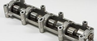
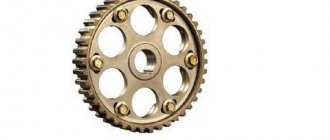
Camshafts with gears and fasteners
In order to install camshafts on the VAZ-2112 16 valves, they must first be dismantled. Like any spare part, they are installed in the reverse order from disassembly.
So, let's look at the step-by-step process of removing and installing the intake and exhaust camshaft.
Removing camshafts
- To begin with, as with any repair operations, it is necessary to remove the “minus terminal” from the battery.
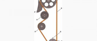
- Remove the timing belt cover.
After unscrewing the mounting bolts indicated in the diagram, remove the timing cover
Now, you need to remove the valve cover. Please note that the bolt tightening order must be followed during assembly.
Unscrew the fastening nuts and remove the valve cover.
Disconnect the wires of the emergency oil pressure sensor, and then unscrew it.
Disconnect the emergency oil pressure sensor
Using a socket wrench or 8mm socket, unscrew the 20 bolts securing the camshaft cover.
Scheme for dismantling and tightening the camshaft bearing housing bolts
- We dismantle the camshaft bearing housing.
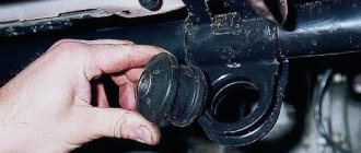
- Now, there is free access to two plugs that are located on the rear side of the cylinder head. We take them out.
- We take out the intake camshaft.
- We take out the exhaust camshaft.
You need to be careful with the camshaft plugs; if you install them incorrectly, oil will leak out. If you don’t notice it in time, you’ll shorten the engine’s lifespan or end up in need of a major overhaul.
Remove the two rear cylinder head plugs
We remove the camshafts from their seats
We press the seals out of the camshafts.
Remove the seals from the camshaft. If it does not come off, carefully cut it or pry it off with a screwdriver.
Installation of camshafts
Now that everything is removed, you can proceed to installing new camshafts on the car:
- Lubricate the cams and shaft support journals with engine oil.
Lubricate the camshaft journals and cams with engine oil.
We place each camshaft in its seat. It is worth considering that camshafts are not interchangeable, so they should not be confused.
The intake camshaft is shown on the left and the exhaust camshaft on the right.
Apply sealant to the surface of the cylinder head and camshaft bearing housing.
How to apply sealant to the camshaft bearing housing cover
We press new oil seals onto the camshafts
Choice
Cylinder head camshafts for the VAZ-2112 are produced only by the manufacturer, so there is no need to look for analogues.
Original catalog numbers: inlet - 2112-1006015, outlet - 2112-1006014. Each camshaft costs an average of about 3,000 rubles.
Intake camshaft marking Exhaust camshaft marking
Nuances
When installing the bearing housing and cylinder head, do not apply sealant that contains silicone. This is due to the fact that the motor heats up, and accordingly the sealant heats up, which releases vapors that can get into the cylinders and further through the system. You should use a sealant whose instructions or packaging indicate that it is safe for the oxygen sensor.
When applying sealant to cavities, you should not apply a lot of it, because when tightening the bolts, it can get inside and this will lead to clogging of the oil channels, and therefore there will be no lubrication. The lack of lubricant will lead to increased wear of parts that will quickly fail.
conclusions
Replacing and installing camshafts on a 16-valve VAZ-2112 is not entirely easy, but it is quite possible. The main thing to ensure results is caution and following instructions. It is worth noting separately that the intake and exhaust camshafts are different and not interchangeable. On the intake there is an additional border for the phase sensor.
16-valve 2008
16-valve 2008
The “smallest” of the 16-valve engines of the Volga Automobile Plant is the VAZ-11194 with a displacement of 1.4 liters. Two 1.6-liter models are also being produced - the already somewhat outdated VAZ-21124 and its more modern and powerful version, the VAZ-21126, which is gradually replacing its predecessor on the production line. Pay attention to the graph with engine characteristics: at crankshaft speeds close to maximum, the power and torque characteristics of the VAZ-11194 and VAZ-21124 are practically the same - and only at lower speeds is the “baby” inferior to its older brother. But engine 21126 is significantly - about 10% - more powerful and high-torque than the other two.
Let's get acquainted with their filling.
Cylinder blocks 21124 and 21126 are cast from cast iron. Compared to the previous one and a half liter analogue 2112, they are 2.3 mm higher (distance from the axis of the main bearings to the upper plane of the block). The cylinder diameter of engines 21124 and 21126 is the same - 82 mm. For selective engine assembly, 21124 blocks according to cylinder diameter are divided into five classes every 0.01 mm (A, B, C, D, E). Block 21126 has three classes separated by the same 0.01 mm (A, B, C). The cylinder class mark is located on the bottom plane of the block.
Other block sizes are identical. But there are differences in the requirements for processing the cylinder walls. Honing of cylinders 21124 is carried out according to the technology and requirements of AVTOVAZ, and 21126 - in accordance with the more stringent requirements of the Federal Mogul company, which have led to stricter requirements for the roughness of working surfaces. In order not to mix up the blocks, in addition to the markings made in the casting on the left wall of the block, the serial number is printed on the rear wall next to the fourth cylinder. Block 21124 is painted blue, and block 21126 is gray.
The cylinder block of the 11194 engine is similar in design to the 21126 block, but the cylinder diameter is smaller - 76.5 mm versus 82 mm. The processing of the cylinder walls is also in accordance with the requirements of Federal Mogul. Markings are in the same places, the block is painted blue. In addition, in block 11194 there are cooling jacket ducts between the cylinders, but 1.6 liter engines do not have them. For selective engine assembly, 11194 blocks are divided into three classes by cylinder diameter at 0.01 mm intervals (A, B, C).
The 21124 engine uses a 2110 connecting rod - steel, I-section, with a steel-bronze bushing in the upper head and axial fixation along the lower head (pictured above). The connecting rod cover is secured with two bolts pressed into the connecting rod. Based on the diameter of the bushing hole for the piston pin, connecting rods are divided into three classes every 0.004 mm. The hole class number is marked on the upper end of the connecting rod.
Engines 11194 and 21126 use connecting rod 11194, which is not interchangeable with connecting rod 2110. The new connecting rod, although it has grown from 121 mm to 133.5 mm, has become lighter - on average, it has “lost weight” from 683 to 412 g, which has seriously reduced inertial loads . Its axial fixation is ensured by the upper(!) head - along the piston. In this case, the steel part is in contact with the aluminum part, which reduces friction losses compared to the 21124 engine, where the steel connecting rod rubs against the cast iron surfaces of the crankshaft, and the friction speed is lower. The lower head, made using breaking technology, has become more elegant. Its cover is attached to the connecting rod with two bolts. Lengthening the connecting rod reduced the force of lateral pressure of the piston on the cylinder.
Replacing camshafts on a VAZ 2114 with your own hands
Camshafts, like other mechanisms and components of a car, determine the quality of engine operation. This material will tell you how to determine the malfunction of the shafts, how to replace the camshafts on a VAZ 2112 16 valves, and what needs to be prepared for this.
The pulleys of the 16-valve VAZ 2112 must be replaced when they are worn out or have mechanical damage. In particular, we are talking about:
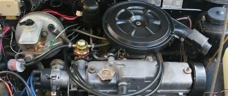
Lada 2112 with 16 cl internal combustion engine
If some kind of extraneous knock appears in the valves while the engine is running, it is usually caused by one of these damages. If you have recorded a reduced pressure of the engine fluid in the system, this may indicate an increase in the clearances in the bearings.
To do this, in order to eliminate this malfunction, it is necessary to grind and restore the pulley bearing journals. You should also enlarge the grooves through which the engine fluid flows. This is done so that the lubricating fluid, after the next grinding, lubricates the internal combustion engine elements. As for the necks, after grinding they should be polished with green GOI paste.
Step-by-step instructions for a 16 valve car
Required Tools
You need to prepare:
- new replacement parts (exhaust and intake timing pulleys);
- 8 mm socket wrench;
- sealant.
New sports shafts Socket wrench “8” Glue sealant
Stages of work
To correctly carry out the process of replacing exhaust elements, we suggest you use the instructions prepared specifically for our users. This manual is also suitable for those who want to replace exhaust camshaft seals, sensors or plugs.
- Open the hood of your 16 valve VAZ 2112. Remove the protective cover of the timing belt.
- After this, it is necessary to remove the cylinder head cover, as well as the engine fluid emergency pressure monitoring device (sensor). The sensor is removed so that it is not damaged during the work. You can also remove the sensor wire tip.
- Once the sensor is removed, you need to remove all the screws that secure the camshaft bearing housing. This is done using an “8” socket wrench. All bolts should be unscrewed evenly, not one at a time.
- After this, dismantle the bearing housing of the exhaust camshafts of the 16 valve VAZ 2112. It should be noted that the housing is dismantled with spark plug wells. They need to be pulled out of the case.
- Now regarding the plugs for technological holes. During the camshaft replacement procedure, motorists often lose the plugs. The plugs are small round shaped parts.
The plugs need to be removed from their installation locations in the cylinder head; there are two plugs in total, and they are located in the area of the rear ends of the camshafts.
Once these items are removed, place them separately. It's better not to lose the plugs.
1. Remove the sensor and unscrew all the bolts 2. Remove the bearing housing 3. Remove the plugs 4. Dismantle the shafts 5. Apply a layer of sealant 6. Tighten the bolts evenly
Video from Artem Ershov “Replacing pulleys on a VAZ 2114”
In this video you can watch the process of replacing pulleys in a 16-valve VAZ car.
Lada Priora Sedan urban aspirated › Logbook › Selection of camshafts
Today we’ll talk about camshafts and how to match them to your needs. When choosing a camshaft for their vehicle, people are faced with the task of selecting the right camshaft for their application. When trying to select a camshaft, they begin to study forums where there is a lot of information about which shafts were installed by whom, in what configuration and how the car drove after all this. The main parameters that appear on the forums are lift, phase and manufacturer. Moreover, some people put the camshaft phase at the forefront and practically pray for this parameter. Quite often on forums you can find phrases: my shaft is wider, which means it will trample better than yours, your phase is a pitiful 262, not like mine is 306! So let's try to understand the parameters of camshafts. The declared phase (also advertised) (264 272 276 306) indicates the maximum duration of the phase in degrees of crankshaft rotation, declared by the camshaft manufacturer; it is measured from the moment the valve begins to lift off the seat until it is completely lowered onto the seat. In real life, this parameter is quite arbitrary; the problem lies in the fact that the first millimeter of lifting and lowering is implemented smoothly so that there is no impact on the seat; it is done to reduce the load on the entire valve lifting mechanism, the camshaft itself, the valve and the seat. Each of these processes takes about
25* crankshaft rotation, that is, in total
50* phases. Based on this, we can conclude that all this time the valve gap is open to a small value and is not able to pass a significant charge of the air-fuel mixture. The effective phase denotes the duration of the phase in degrees of rotation of the crankshaft, measured from the moment the valve lifts off the seat by 1 mm until it lowers to the same height at the end of the phase, and different manufacturers can come up with any other lift value; 0.05 inches = 1.27 mm is used abroad. After the valve begins to tear away from the seat, or rather the separation has passed the notorious 1 mm, it begins to quite aggressively increase the valve lift and, as a result, the valve gap is capable of allowing a significant amount of fresh air-fuel mixture to pass through. The maximum possible lift of the valve and the duration of its stay at the peak of lift also depend on the effective phase. The duration of the effective phase is the main figure when comparing camshaft phases, and the effective phase, the advertising phase, is not such a parameter. Valve lift height. This is the maximum height of valve lift from the seat; the greater the height of valve lift, the more the intake valve opens and creates better purging of the channel. It is very important to understand that this is a peak value and the valve spends only a small period of time (phase) at this height, the rest of the time it either rises towards it or falls away from it, there are camshafts with a long dwell time, the camshaft profile is distinguished by a rather wide cam top, this gives keeping the valve at the required height for as long as possible. However, this method has geometric limitations and increases the load on the entire gas distribution mechanism. In our realities, manufacturers prefer not to provide data on camshafts, only in rare cases when they are made publicly available, and this does not bring honor to the manufacturer. Essentially, if you have a specific camshaft on hand, you have no problem measuring its phasing, or even sending it to a copying machine and making a copy. In fact, in a similar way, camshafts of the “USA type” are sold on the market, at one time successfully dug up and released into such free access due to the absence of copyright holders (developers) who can make claims. Although the camshafts are successful and are in deserved demand. What does it all look like
On sale you can find a huge number of camshafts for any choice, the declared phase can begin with 232 and end with 320, we’ll try to figure out how not to get confused in all this variety and how to choose the right camshaft. So we usually have a 16 valve engine, an 8 valve front-wheel drive and an 8 valve classic internal combustion engine. To go further we need to decide what camshaft phasing is. Next we will see what camshaft diagrams look like
Based on theory and experience, we can draw a brief conclusion that if you want to achieve certain indicators on any of the engines, then you will need for the classic family in the declared phase it will look like this: 270 phase has an optimal range of 1000-5500 280 phase has an optimal range of 1500-6500 290 phase has an optimal range of 2500-7000 300 phase has an optimal range of 4000-7200
The standard classic camshaft has the characteristics of a lift of 9.5 mm, an exhaust phase of 55-30 (before BDC after TDC), an exhaust phase of 30-55 (before TDC after BDC)
If we have a front-wheel drive 8 valve ICE: 270 phase has an optimal range of 1000-6000 280 phase has an optimal range of 2500-6400 290 phase has an optimal range of 3000-6800 300 phase has an optimal range of 4000-7000 ICE 2108 intake lifting 8.8 mm, an inventure of 8.8 mm. exhaust 8.65mm, intake phase 294 degrees, exhaust 256 degrees. Standard camshaft ICE 2110, intake lift 9.4mm, exhaust 8.95mm, intake phase 255 degrees, exhaust phase 247 degrees.
If we have 16 valve ICE 270 phase has an optimal range of 1500-7000 280 phase has an optimal range of 2500-8000 290 phase has an optimal range of 3500-9000 300 phase has an optimal range of 4500-10000, the standard dvigalum of the ICE 2112 7.6mm lifting, phase, phase, phase lift, phase, phase intake and exhaust 256 What needs to be added is the general sensations from installing a camshaft with some characteristic; we will talk about camshafts gradually, starting from a small phase. So what do we get with a camshaft with phasing: 270 phase is an entry-level camshaft, for a classic internal combustion engine it is practically factory-made on such a camshaft. These camshafts provide smooth idling, improved performance across almost the entire range, and moderate fuel efficiency. Usually on such camshafts the phasing is 25-65-65-25 or close to it. They are not critical to modification of the cylinder head; they usually do not require high overlaps.
280 phase is the “next step” camshaft; on these camshafts, the idle speed is no longer as smooth as desired, they are more demanding in terms of cylinder head modifications, their overlap is usually quite high, and fuel consumption is increased. The phasing of such camshafts is approximately 32-68-68-32. Camshafts of this type can be classified as high efficiency; the output from such camshafts is in some way optimal, the engine still remains moderately urban and allows you to accelerate sharply, surprising your downstream neighbors. The problem with the factory intake and exhaust begins to noticeably manifest itself.
Phase 290 is the camshaft of a terminally ill person, the idle speed on such camshafts is already quite “noble”, a bumping noise can be heard and felt, the overlap on such camshafts is usually around 2 mm, as a result of which the idle speed and fuel consumption are significantly increased. These camshafts are very critical to modifications to the cylinder head, intake and exhaust systems. The phasing of such camshafts is approximately 37-73-73-37
300 phase and above is a camshaft for sports cars (they are called cramps), the idle speed on them is very uneven and is around 1500 rpm. The overlaps are in the range of 2.5 mm or more; not every piston engine can have such overlaps; this type of camshaft does not work on small ones. They require accurate and competent selection of intake and exhaust components, as well as modification of the cylinder head. They work only in the high-speed zone; up to 4000-5000 revolutions there is practically no torque, as one of my good friends puts it, “there’s no one at home.” Designed for motorsports, not recommended for use in the city.
A short video about this. The choice of camshaft is the basis of the characteristics of the internal combustion engine! This method is basic, this is how you can determine the necessary characteristics and then a more accurate selection is made in the Engin Analyzer Pro program, and this is how the hardware for my Priora is actually selected.
source
How to distinguish the intake camshaft from the exhaust camshaft of a VAZ-2112: photo
The camshafts of the 16-valve VAZ-2112 admit the working mixture and release exhaust gases. Unlike an 8-valve engine, where one camshaft serves for intake and exhaust, on a 16-valve engine there is a separate element for each phase. This improves not only engine performance, but also contributes to lower fuel consumption.
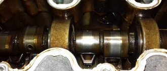
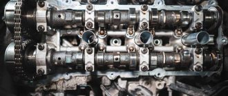
Photo of intake and exhaust camshafts
The intake and exhaust camshafts are indicated by arrows in the photo. The photo shows the engine with the valve cover removed.
Camshaft difference
The difference between the intake and exhaust camshafts is the presence of a groove for the phase sensor
In fact, there is no difference in the design of the exhaust and intake camshafts. There is only one reason why they are not interchangeable. There is a lip on the intake camshaft that is designed for a valve timing sensor.
Some car enthusiasts install sports camshafts instead of standard factory camshafts, which increase power. This is where the significant difference begins.
The intake camshaft has a larger cam size, which in turn opens the valve not by 7.6 mm, but by 13.2. This allows the engine to increase power characteristics. So the exhaust itself has slightly different characteristics - the valve opens not by 7.6, but by 10.8 mm, which significantly adds power.
Differences in sporty camshafts
conclusions
The camshafts of the 16-valve engine on the VAZ-2112 do not differ in design features, except that an additional edge is machined on the intake shaft for the camshaft (phase) sensor. If the intake and exhaust elements are swapped in places, this will lead to a violation of the valve timing, and if the engine operates in this mode for a long time, the owner will inevitably face a major overhaul of the cylinder head, at best.
Advantages of a sixteen-valve engine
We have already said that the internal combustion engines of the VAZ-2110 (2112) family discussed in the article are distinguished by greater power, lower fuel consumption, and also high technical characteristics, unlike the V8s. It's time to find out what design features make the VAZ 2112 16 valve engine such an attractive choice for motorists.
Let’s immediately make a reservation about exactly what “advantages” will be discussed in this section of the article:
- fuel economy;
- higher power;
- detonation resistance;
- advanced cooling system;
- simple tuning due to the separation of the intake and exhaust tracts.
It is the separation between the intake and exhaust tracts in the design of the VAZ-21120 and 21124 engines that makes it possible to achieve quite noticeable fuel savings. Thus, the supply of fuel and the intake of exhaust gases is carried out by a separate spaced valve system, due to which there is no unwanted mixing of fuel and combustion products. It is also obvious that this increases the efficiency of the engine and its power.
Tightening torque for VAZ-2112 camshaft bed 16 valves: order
Many motorists have heard that it is necessary to correctly tighten the threaded connections on the 16-valve VAZ-2112 engine, but they have never done it themselves. Thus, the tightening torque is determined by the manufacturer and is indicated in the service repair manuals.
Video about installing camshafts and split gears on a 16 valve engine
The video will tell you how to properly tighten the threaded connections on the camshaft beds
Torque and sequence of tightening the camshaft bed
Camshaft cover tightening sequence
Correct tightening of the camshaft bed, as well as other parts of the cylinder head, determines the normal functioning of all components and assemblies. So, in order to tighten threaded connections, a standard tightening pattern and a torque wrench are used.
Before installing the bolts in place, they must be washed thoroughly and lubricated with silicone grease.
In order to properly tighten the bolts, you need to know the sequence. It starts from the middle part and gradually moves directly to the edges. The detailed sequence can be seen in the photo below.
Tightening diagram for each camshaft bed bolt with numbering
As for the tightening force itself, it is 8.0-10.0 Nm. After the bed is installed on the block head, the connection bolts are tightened by hand or without much force using a ratchet with a head.
We tighten all the bolts by hand, but do not tighten them
When all the bolts are in place, you need to take a torque wrench and tighten them according to the standards in the order indicated above.
Torque wrench for tightening threaded connections
In what cases is it necessary to tighten the camshaft bed?
The bolts are tightened. Marked with arrows
Tightening the camshaft bed will be necessary if it was previously dismantled for restoration and repair work. So, in what cases will you need to remove the bed, let’s look at it in more detail:
- Replacing camshafts, lifters or valve seals.
- Overhaul of the block head.
- Engine repair operations.
- Replacement of individual elements of the cylinder head.
Consequences of improper bed tightening
The consequences of improperly tightening the camshaft bed include the following:
- Oil leakage due to a gap or loose connection.
- Passing air inside the cylinder head.
- Malfunction of the engine or cylinder head.
- Ingress of foreign objects (water, dirt, dust).
All these factors can negatively affect the performance of the cylinder head and main power unit.
conclusions
The torque and sequence of tightening the camshaft bed on the 16-valve VAZ-2112 engines must be correct, since this factor affects the operation of the cylinder head and the engine as a whole. Thus, incorrect implementation of the procedure can lead to more serious consequences. If the car enthusiast is not able to do this on his own, then it is necessary to contact a car service, where everything will be done quickly and efficiently.
The work is shown on engine 21124. For details of performing work on engine 2112, see the text.
1. We prepare the car for work (see “Preparing the car for maintenance and repair”).
Lada Priora Hatchback › Logbook › Installed camshafts nuzhdin 8.7
In general, I installed the rollers on the machine! Priora with air conditioning and this caused a lot of difficulties through which I had to go through sleight of hand and mind. In this article I will help you walk this difficult path :))
First, we go to the store, or rather, we go and stock up on the following tools:
1) Heat-resistant sealant - red in a syringe 2) Camshaft seals and plugs, if the mileage is over 100 tons km 3) Timing belt, pump, rollers, if the mileage is over 50 tons km 4) A 13-socket wrench with a moving joint 5) A flexible screwdriver with nozzle 13 6) Heads: 8, 13, 10 and a wrench, respectively 1/2 7) Napkins, rags, rags, cotton swabs Long screwdriver with a flat slot, and also a screwdriver with a Phillips + flat slot 9) Hydraulics from 3 pcs up to 16, depending on the mileage of the car 60 t. km - 200 t. km 10) Priorovsky pulley tensioner, generator belt roller tensioner + 17 socket wrench 11) Set of hexagons 12) Spare bolts 2-3 pcs for cylinder head bed and valve cover .
Let's get started: 1) remove the filter box by taking out the rubber supports. Either replace them later, or use a sharp knife to trim the rubber on top, remove them from the filter box, and put them on the supports on the machine, and then place the box on them. 2) remove the corrugation going from the air flow sensor to the throttle 3) remove the throttle valve by unscrewing the bolts 13 4) remove the low crankcase ventilation and high crankcase ventilation hoses, remove the throttle control rod, move the throttle down, do not touch the cooling system hoses. 5) disconnect the vacuum brake booster hose from the receiver 6) remove the individual ignition coils by unscrewing the bolts by 10 7) move the braid to the side with the ignition wires to the side and the other braid. unscrew the belt roller with a 17 wrench generator-crankshaft-conder and remove it as well as the belt to the side 9) unscrew the upper support of the generator with 13 wrenches, move it to the side 10) unscrew the upper receiver supports with a 10 wrench, put all the nuts in the box. 11) from below, on the pit, unscrew the 3 nuts securing the receiver along the contour, using a 13mm wrench with a hinge. as well as the rightmost bolt. We tore it off with a key, then unscrew it by putting the head on 13 by hand. Do not lift the car with two jacks! If there is a crankcase protection, unscrew it first. 12) we tear off the left bolt with a spanner wrench and unscrew it with a bendable screwdriver with a 13-short nozzle. 13) remove the receiver, move it towards you, don’t forget to find all 5 washers! 14) use two flat-head screwdrivers to remove the plugs from 4 injectors, it’s very inconvenient, there’s a lock on the plug, we bend the wire on the plug from below with a screwdriver, you’ll see it opens on the sides. Without this, the receiver cannot be removed without damage. 15) remove the receiver, half the battle is over! 16) remove the plastic timing belt protection using the hexagon from the kit 17) jack up the right front wheel, turn the wheel until the top dead center and the marks on the pulleys match, engaging 5th gear. There is a mark on the toothless pulley at the bottom, and slots on the top of the pulleys. If you change the timing belt, you need to remove the wheel and pulley. 18) tear off the nuts on the pulleys, securing the pulley from turning 19) unscrew the tension roller with a 15 wrench 20) remove the timing belt from the camshaft pulleys and to the side, do not allow oil to get on it! 21) unscrew the nuts on the pulleys and remove the pulleys 22) along the contour, unscrew the 8 bolts on the cylinder head valve cover. 23) remove the valve cover, we see the bed with camshafts. 24) unscrew the 8 bolts along the contour on the cylinder head bed. 25) remove the bed and take out the camshafts. We check the hydraulics for compression by pressing with a finger; if there is compression, replace them. We remove all the hydraulics and check whether the new camshafts rotate. put the hydraulics in place. 26) coat the adjacent parts of the bed with a thin layer of sealant, having previously degreased them. 27) place the other shafts with the keys up, the guideline is TDC slots. There are two inlet tides, one outlet. 28) tighten the bed bolts along the contour not to a torque of 20 nm, but most likely to 10 nm, otherwise they will spin and break off. you will feel when the limit is reached, if they start to scroll, unscrew and re-tighten another new bolt. I already picked one, fortunately it came out of the woodwork. Walk along the bed, smoothly, increasing the tightening force, over all bolts. Don’t forget about the camshaft seals, it’s better to install them before tightening the cylinder head bed, as well as the plugs. 29) also with the valve cover, but first, put on the pulleys and align them with the TDC slots. 30) Check all the marks and put on the timing belt, roller, and spin the wheel, then check that all the marks match. 30) everything is in reverse order. Tired of writing, let alone doing it all!
source
Photo of intake and exhaust camshafts
The intake and exhaust camshafts are indicated by arrows in the photo. The photo shows the engine with the valve cover removed.
Camshaft difference
The difference between the intake and exhaust camshafts is the presence of a groove for the phase sensor
In fact, there is no difference in the design of the exhaust and intake camshafts. There is only one reason why they are not interchangeable. There is a lip on the intake camshaft that is designed for a valve timing sensor.
Some car enthusiasts install sports camshafts instead of standard factory camshafts, which increase power. This is where the significant difference begins.
The intake camshaft has a larger cam size, which in turn opens the valve not by 7.6 mm, but by 13.2. This allows the engine to increase power characteristics. So the exhaust itself has slightly different characteristics - the valve opens not by 7.6, but by 10.8 mm, which significantly adds power.
Differences in sporty camshafts
Cylinder head repair
We mark all hydraulic compensators with numbers using an ordinary clerical touch and put them away. An ordinary magnet will help you pull them out. We dry out the valves and remove the oil seals (valve seals), the valves into scrap metal, the oil seals into the trash. We clean all channels. We take the head for grinding, just in case. After washing it again with kerosene after sanding and blowing it with air, we begin to assemble it.
We arrange the freshly purchased valves in the sequence in which they will stand in the cylinder head and begin to grind in one by one. Lubricate the valve stem with clean oil and apply lapping paste to the edge.
We insert the valve into place and put a valve grinding tool on the valve stem. The stores sell a device for manual lapping, but since this is the twenty-first century, we are mechanizing the process. We take the old valve and cut off the rod from it, select a rubber tube for it of such a diameter that it fits tightly. The rod is in a reversible drill, one end of the tube is on it, the other is on the valve being ground in. At low speeds we begin to grind the valve, constantly change the direction of rotation and periodically press it to the seat or weaken the force. On average, the valve takes about twenty seconds. We take it out and wipe it. The valve is considered ground in if a uniform gray strip of at least 1.5 mm wide appears on the chamfer.
The same stripe should appear on the valve seat.
Video of manually grinding valves
For a sixteen valve head, everything is the same, only there are twice as many valves. After lapping, all valves and seats are thoroughly wiped and washed with kerosene to remove any remaining lapping paste. We check for leaks. We tighten the old spark plugs and put all the valves in place. Pour kerosene and wait three minutes, if the kerosene does not run away all is well, otherwise we grind the valves on this cylinder.
We had to grind four valves again, after which the kerosene stopped flowing.
We stuff new valve seals.
We put the valves in place and dry them. Before doing this, lubricate the valve stems with clean oil. After lubricating it with clean oil, we put the hydraulic compensators in place and, covering them with a clean cloth, remove the head out of sight. We're done with the cylinder head.
Process Features
Each engine has its own torque, as does the pin tightening pattern. The indicator of this moment is influenced not only by the type of engine, but also by other factors that you need to know if you decide to carry out this procedure yourself.
The same factors:
- how well the pin holes are lubricated and the very condition of the elements;
- the quality of the bolts plays a big role - bad or old ones may not survive tightening;
- if the thread or the pin itself is deformed, it is better not to tighten it. Because after a short period of time, all elements that do not meet operating standards will fail.
The most urgent need for the tensioning procedure occurs when dismantling the cylinder head, as well as when reinstalling it.
Some car enthusiasts tighten very elongated bolts in 4 stages. In this case, at the second step the torque is 70-85 N*m, which is absolutely unacceptable when working with a Lada Priora engine with 16 valves.
The correct sequence of tightening the keys is very important. Only in this case will the head correctly perform its primary and secondary functions.
Before installation, be sure to clean all threaded bushing holes. Then all the bushings are placed in place, and a gasket is placed on top. All metal elements must be free of grease.
No sealants or other lubricating oils are used during gasket installation.
In what cases is it necessary to change?
The pulleys of the 16-valve VAZ 2112 must be replaced when they are worn out or have mechanical damage. In particular, we are talking about:
- failure or exhausted service life of the pulley bearing journals;
- mechanical bending of the camshaft;
- spent service life, as well as scuffing of element cams.
Lada 2112 with 16 cl internal combustion engine
If some kind of extraneous knock appears in the valves while the engine is running, it is usually caused by one of these damages. If you have recorded a reduced pressure of the engine fluid in the system, this may indicate an increase in the clearances in the bearings.
To do this, in order to eliminate this malfunction, it is necessary to grind and restore the pulley bearing journals. You should also enlarge the grooves through which the engine fluid flows. This is done so that the lubricating fluid, after the next grinding, lubricates the internal combustion engine elements. As for the necks, after grinding they should be polished with green GOI paste.
conclusions
The camshafts of the 16-valve engine on the VAZ-2112 do not differ in design features, except that an additional edge is machined on the intake shaft for the camshaft (phase) sensor.
If the intake and exhaust elements are swapped in places, this will lead to a violation of the valve timing, and if the engine operates in this mode for a long time, the owner will inevitably face a major overhaul of the cylinder head, at best.
Replacement of camshafts on the 16-valve VAZ-2112 engine occurs when they wear out and the support journals wear out. Most often this happens when the time for a major overhaul of the power unit or cylinder head passes. This is a rather complicated procedure, but you can really do it yourself.
The video below shows the installation of camshafts and split gears on a 16-valve engine of the VAZ family
The video material will tell you how to replace camshafts on a VAZ-2112 16 valves, and give some recommendations and advice.
conclusions
Replacing and installing camshafts on a 16-valve VAZ-2112 is not entirely easy, but it is quite possible. The main thing to ensure results is caution and following instructions. It is worth noting separately that the intake and exhaust camshafts are different and not interchangeable. On the inlet there is an additional border under.
Camshafts, like other mechanisms and components of a car, determine the quality of engine operation. This material will tell you how to determine the malfunction of the shafts, how to replace the camshafts on a VAZ 2112 16 valves, and what needs to be prepared for this.
[Hide]
Help me deal with Priora!
#1 Offline Victor2109
In general, I decided to make a capital investment and already regretted that I did not contact the service and decided to save!
The problem is that after a do-it-yourself overhaul the car will not start, the Priora engine is 126,
In general, what we have: fuel supply - the injectors are working, they spray correctly,
spark is good - coils, spark plugs are new, working,
the marks (and no matter how hard I tried) are right, perfect)
We flashed the ecu, as soon as we didn’t flash it, it just started,
RESULT: WILL NOT START, hits the muffler in the air vent, tries to make the sound that it should, but in vain,
don’t scold me))) I will be glad for any help!
From attempts, oil was poured into the cylinders mixed with gasoline - 0, marks on the camshafts
I tried a tooth ahead - 0, with a pusher - 0, in general I have no strength anymore))) it’s a shame)) what could have gone wrong, where to look for the problem.
#2 Offline Zahar
Moderator 17,992 Messages:
1. I don’t remember well anymore, let someone in the know correct me. according to the marks, the crankshaft makes two revolutions, and the camshaft makes one revolution, sometimes the marks coincide, but it is still not set correctly, you need to remove the belt, turn the crankshaft one revolution, and again the marks will coincide. So?
Consequences of untimely shift
If the timing belt is not changed in a timely manner, it may break. While driving on the highway, this can lead to an accident. If the accident was avoided, you will have to spend money on a tow truck to deliver the car to the repair site. If the belt breaks, the movement of the camshafts and valves will stop, but the movement of the crankshaft will continue, which may result in damage to the valves as a result of the impact of the pistons. Repair may be limited to replacing the timing belt and rollers. But only if an 8 valve engine or 16v 1600 cc is installed. cm, that is, safe from the point of view of bending the valves (21114, 21124 or simply 124).
If the valves are bent, a major overhaul of the engine will be required, which will cost from 20–30 thousand rubles. In some cases, it will be cheaper to purchase a new engine, although this will lead to other problems - registration. Based on the above, it is much easier, safer and cheaper to change an inexpensive part on time.
The video shows the process of replacing the timing belt on a VAZ 2112. Filmed by the ExpertR channel.