Error P0500 symbolizes a malfunction in the vehicle speed sensor or its electrical circuit (“Speed sensor error” or in English - Vehicle Speed Sensor). Moreover, this error occurs on cars equipped with an anti-lock braking system (ABS), which prevents the car from skidding. The fact is that the operation of the mentioned system is controlled by the electronic control unit (ECU) of the car, in particular, it compares the speed of rotation of the crankshaft and the wheels themselves. A four-pulse signal with relevant information passes through the ECU. To generate error P0500, five conditions must be met simultaneously.
As for diagnosing the P0500 code, you can do it yourself, with only an electrical tester (multimeter) and basic plumbing tools. As practice shows, error code P0500 often results from a break in the signal wire or a critical decrease in the value of its insulation (simply put, it is frayed). According to statistics, a similar error occurs more often than others in the following car brands: Toyota, Ford, VAZ, Peugeot, Chevrolet and Opel.
Reasons for error P0500
Regardless of the machine model, the reasons for the formation of the P0500 code may be one or more of the following reasons:
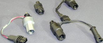
- Faulty speed sensor on one or both (four) drive wheels.
- Broken wire or short circuit in the electrical or signal circuit of the speed sensor.
- Poor contact in the electrical or signal circuit of the sensor (there can be many options, from oxidation to poor connection of the chip).
As a rule, the cause of a speed sensor error code is poor electrical contacts or their complete absence. Then, during diagnostics, the program displays a message stating that there is no signal from the vehicle speed sensor.
Symptoms of a Vehicle Speed Sensor error
Outward symptoms of a P0500 code include one or more of the following:
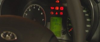
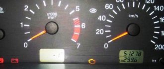
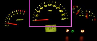
- The speedometer and/or odometer (if equipped) does not work fully or partially (incorrectly). This is especially true for electronic speedometers.
- Cars with automatic transmissions may shift incorrectly (incorrectly) because the ECU cannot make the correct decision about how fast the car is going.
- The ABS system and/or traction control system (TCS) may be disabled (the ECU forces them into limp mode).
- The ABS and/or brake warning lights on the instrument panel are activated.
- On some machines, the maximum speed and/or engine speed will be forced to be limited.
If at least one of the listed problems occurs, it is necessary to diagnose the ECU using appropriate software.
Conditions for generating error code P0500
To generate error code P0500 and, accordingly, activate the Check Engine warning light on the dashboard, the following five conditions must be met:
- The angular speed of rotation of the engine crankshaft exceeds 1600 rpm.
- The engine coolant temperature exceeds +80 degrees Celsius.
- The ECU information signal about the vehicle speed corresponds to 5 km/h (for some cars this value may differ, for example 9 km/h) or less.
- Load parameter TL exceeds time 3 milliseconds.
- The four conditions listed above collectively last 4 seconds or more.
However, it should be noted that the Check Engine lamp is activated the first time on cars with an automatic transmission, and the second time (second trip, starting) on cars with a conventional manual transmission.
On which cars is this problem most common?
The problem with the P0500 code can occur on different machines, but there are always statistics on which brands this error occurs more often. Here is a list of some of them:
- BMW (BMW X5)
- Chery (Chery Amulet)
- Chevrolet (Chevrolet Captiva, Epica)
- Chrysler
- Citroen (Citroen C4, C5)
- Daewoo (Daewoo Matiz)
- Dodge (Dodge Caravan, Stratus)
- Fiat (Fiat Ducato)
- Ford (Ford Mondeo, Transit, Fiesta, Focus, Fusion, Explorer)
- Honda
- Hover
- Hyundai (Hyundai Porter, Santa Fe, Sonata, Elantra)
- Infiniti
- Isuzu
- Jeep
- Kia
- Land Rover (Land Rover Range Rover)
- Lexus (Lexus lx470, rx300, rx330, rx350)
- Mazda (Mazda 3, Mazda 6, Demio, Premasi, Familia, MPV)
- Mercedes (Mercedes Sprinter, w203, w210, w211)
- Mitsubishi (Mitsubishi Karizma, Lancer, Pajero, Tsediya)
- Nissan (Nissan Almera, Maxima, X-Trail)
- Opel (Opel Antara, Astra, Vectra, Zafira, Meriva, Omega)
- Peugeot (Peugeot 206, 207, 307, 308, 607, Boxer, Partner)
- Renault (Renault Logan, Megan)
- Subaru (Subaru Outback, Impreza, Legacy, Tribeca, Forester)
- Suzuki (Suzuki Grand Vitara, sx4)
- Toyota (Toyota Avensis, Auris, Venza, Vista, Vitz, Kaldina, Camry, Carina, Corolla, Crown, Land Cruiser, Mark 2, Platz, Prado, Premium, Rav4, Celica, Fielder, Funcargo, Highlander, Hilux, Harrier, Chaser , Echo, Yaris)
- Volkswagen (Volkswagen Transporter)
- Volvo (Volvo s60)
- VAZ 2105, 2107, 2110, 2112, 2114, 2115
- Gazelle
- Lada Granta, Kalina, Largus, Niva, Priora
- UAZ Bukhanka, Patriot
You can sometimes encounter other errors with the P0500 fault code. The most common are the following: P0036, P0056, P0102, P0130, P0136, P0325, P0444, P0501, P0502, P0503, P0505, P0600, P0700, P0717, P0720, C1408, U1113.
Checking the System Status
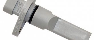
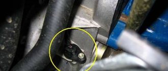
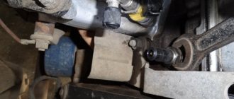
Problematic components in this case may be the speed sensor (on front-wheel drive vehicles it is installed on the hub bearing, on rear-wheel drive vehicles - on the gearbox or differential), the instrument panel (panel, its electronic part), the on-board control system (ECM in the English abbreviation). Before checking, it is advisable to make sure that the speedometer in the car is working correctly. It’s easy to verify this by taking a short trip.
If error code P0500 occurs, you must do the following:
- Using special diagnostic equipment, it is checked whether the speed sensor is working properly. If the appropriate equipment is not available, then you can install a known working sensor of a similar model on the machine.
- Using a multimeter, check whether the circuit between the sensor input signal and its ground or power wire is closed (often, it is due to insulation failure that a short circuit occurs in the circuit, and, accordingly, incorrect operation of the sensor and the entire system).
- Using a diagnostic tool, find out whether the forming voltage from the sensor arrives several times per second along the signal cable. Moreover, the connection may be interrupted for the first few seconds, but then restored again.
- The connection between the sensor and its ground is checked.
- If the sensor is four-wire, then the integrity of the fourth wire is also checked using a multimeter.
Please note that when starting and stopping the car in place, the connection with the sensor is interrupted, but is restored immediately while moving. Therefore, the verification process is performed according to a certain algorithm.
Replacement procedure
- Park the car on a level surface and secure it with the parking brake.
- After opening the hood, turn off the power to the on-board circuit by removing the ground wire from the battery terminal.
- For ease of operation, remove the air duct corrugation by loosening the clamp securing it to the mass air flow sensor. Move it aside.
- Disconnect the wires on the sensor by removing them from the connector.
- Using a socket wrench or a 10 mm socket, unscrew the bolt securing the sensor housing.
- Using a slotted screwdriver, pry up the housing and remove the sensor from the gearbox.
- Install a new sensor in its place.
- Connect the connector.
- Install the duct corrugation.
- Connect power.
How to Test P0500 Speed Sensor
The connection diagram for different car brands will be different, but the general logic for checking the speed sensor will be the same. Let's consider the procedure on the Toyota RAV 4, a popular car in the domestic space. Diagnosis of the error must be performed using a special diagnostic tool. Depending on your model and software hardware used, some steps may vary. The algorithm has the following actions:
- Position the drive wheels so that they rotate freely.
- Connect the ECU connector and the diagnostic tool (laptop) to connector DLC3 using a signal cable.
- Turn on the ignition and the diagnostic tool. Select a menu in its program that shows the actual speed of the vehicle.
- “Drive” the car a short distance, while noticing the speedometer readings. Stop the spinning wheels. See what speed the program noted and compare them. If everything matches, then it is enough to reset the error programmatically; most likely it is an episodic operation.
- If the readings are different, the next step is to check the instrument panel for the voltage value. To do this, disconnect connector E22 (power) of the instrument panel and turn on the ignition.
- If everything is in order, then between ground and contacts E22-39 there will be a voltage in the range from 9 to 14 Volts. Note! This action must be checked both with non-rotating and rotating wheels. However, you need to rotate the wheels not with the help of the engine, but mechanically (manually, with the gearbox in neutral).
- Next, you need to measure the resistance of the wire between contacts E22-39 and A12-8, that is, check for opens and short circuits. The resistance of the specified wire according to the multimeter should not be lower than 1 Ohm and not exceed 10 kOhm. Otherwise, there is a wire break or short circuit (insulation damage).
- In rare cases, the controller malfunctions. If the voltage value is +12 V, then there is a short circuit to the power source. The controller may also fail. For additional diagnostics, it makes sense to start the engine, then touch ground with one probe and contact No. 2 of the wiring harness block from the sensor with the other. In this case, you need to look at the readings of the diagnostic device (program). If the speed value there is indicated as 0 km/h, then the controller has failed.
- Under similar conditions, you need to check the voltage between ground and contact No. 1 of the harness block. If there is voltage there, good, otherwise the wire breaks or is damaged (its insulation often fails).
- Under similar conditions, you need to check the voltage between ground and wire No. 3 of the harness block. If there is voltage, it means the sensor is either completely faulty or has poor contact. If the voltage does not pass through the multimeter, the wires are broken.
Interestingly, in some cases, poor insulation may interfere with the speed sensor signal from other systems. For example, in Toyota Camry cars, the described problem occurs when there is interference from parking sensors located nearby in the wiring harness. Therefore, it makes sense to inspect and check not only the insulation of the sensor wires and its system, but also others located in close proximity to it.
A more detailed check of the sensor involves the use of an oscilloscope. With its help, you can find out not only whether information is coming from different sensors of the drive wheels, but also look at the signal shape. And in some cases, the shape can be used to judge the operation of the ABS system. There are known cases when the ABS ring on one or the other drive wheel began to rotate itself, that is, to work out of synchronization with the CV joint. And this leads to a situation where the ECU receives false information. And in some cases (but not always, it depends on the ECU firmware), such a situation is the direct cause of error P0500.
Diagnosis P0500
The following steps will help you resolve the P0500 code.
Inspecting the Sensor and Connections
Many problems can be easily found in the harness and connectors. Begin diagnostics by visually inspecting the sensor and its connections.
Check the DS using a diagnostic tool
Connect a diagnostic tool or adapter and view real-time data. Monitor the speed readings as you drive and see if they match your speed. To do this, you can use the Torque program.
If the readings do not match your actual speed, there is something wrong with the sensor or its circuit. If the readings match but the P0500 code does not go away, you likely have an intermittent fault.
Check sensor output
If the car has not passed the tests listed above, then it’s time to determine which part of the DS circuit is at fault. The testing process is slightly different depending on the type of sensor.
Reed sensor
To test the reed switch, turn the speedometer cable or wheel and use a multimeter to see if the circuit opens or closes.
Permanent magnet sensor
The permanent magnet sensor can also be tested using a multimeter. Remove the connector and connect the device to the sensor terminals.
Most DS should show values between 190 and 250 ohms , but it is recommended to refer to the manufacturer's specifications for exact information.
Naturally, if the multimeter shows “OVER”, “OL”, or “1”, then the sensor should be replaced.
Then raise the car. Rotate the wheels and watch the ohmmeter - the readings should fluctuate. This can also be done with a multimeter set to read alternating voltage (AC). If the readings do not change, the sensor is faulty and must be replaced.
Hall effect sensor
Using information from the repair manual, determine which terminal on the sensor connector is the signal return wire. Using a multimeter in DC voltage mode, check the sensor return wire.
Connect the black test lead of the multimeter to the battery negative. As you turn the wheels, you should see the voltage reading on the meter change.
Checking the speed sensor with an oscilloscope
Although a multimeter can be used to test speed sensors, it is much better to test them using an oscilloscope. It allows you to view the sensor waveform and check for inconsistencies.
The magnetic sensor produces a variable sinusoidal waveform. The Hall effect sensor produces a square waveform. This signal never falls below the zero point.
Check speed sensor circuit
If you have checked the speed sensor and the P0500 code is still present, you need to check the sensor circuit.
Checking the Reed Switch Circuit
The reed switch circuit is quite simple. The sensor will have two wires going to it: power and a return signal to the ECU. Check your vehicle's repair manual to determine which wire is which.
- Set the multimeter to DC voltage measurement mode. Connect the red lead of the multimeter to the power pin on the connector and the black lead to ground. In most cases you should see around 5 volts.
- Then check the continuity of the circuit to the control unit. This can be done by touching one test lead to the return signal contact on the sensor connector, and the other to the signal contact on the ECU. Set the multimeter to measure resistance ("Ohms") - a value should appear on the screen. If instead the device shows “OL” or “1”, then you have an open circuit.