The utility vehicle, or as it is also called the commercial vehicle, VW Transporter T5 was produced by German manufacturers from 2003 to 2014. However, even today you can find this reliable, roomy car on the country’s highways.
Years and roads take their toll - a car sometimes breaks down right on the highway. Very often the cause of a breakdown is a small part of the electrical circuit of the Volkswagen Transporter T5 - a fuse. Even a novice driver can easily replace a burnt-out insert and restore the car’s performance. In our review we will tell you where the T5 power supply protective blocks are located and how to replace the defective part.
Where are they located?
Every Volkswagen Transporter owner has faced this question. If you have recently acquired this machine, we will help you solve this problem. Volkswagen Transporter T4 and T5 vehicles have different fuse blocks.
Volkswagen Transporter T5
The main power supply with fuses and relays in the T4 Transporter is located inside the vehicle. Many car owners encounter a problem at first glance. Its location is not highlighted in any way, so motorists will need to consult their owner's manual to identify it. But it's not that difficult. The power supply is located on the left under the steering wheel. It is hidden behind a protective plastic strip that must be opened to access the device.
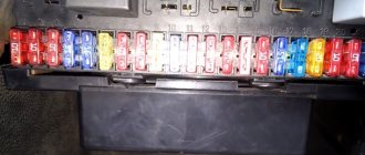
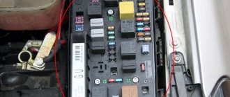
As for the T5 model, here the developers have implemented several power supplies. One of them is located in the car's interior, the other in the engine compartment. Finding these power supplies is not difficult: one of them is located in the middle of the dashboard, and the other is in the battery compartment in the engine compartment.
General vehicle documentation
Transporter 2004 model (rus.)
Design and description of the model. Self-education program manual. Brief description, Body, Passenger safety, Engines, Transmission, Chassis, Electrical equipment, Heating and air conditioning, Maintenance.
Volkswagen T5 2010 model year (rus.)
Self-education program manual.
Contents: 2010 T5 Model Line, Technical Specifications, Body, Emergency Tailgate Release, Passive Restraint Systems, Engine, Engine and Transmission Combinations, Transmissions, All-Wheel Drive System, Chassis, Brake System, Steering, Heater and Air Conditioning installation, Auxiliary heaters, Electrical equipment: Installation locations of control units, Data bus topology, Onboard power supply control unit J519, Lighting devices, Lane change assistant, Rear view camera, Front panel, Interface for connecting multimedia devices (MediaDeviceInterfaceBox), Head unit, telephone and navigation system, Head unit and radio navigation system, Antenna installation concept, Universal telephone connection kit (UHV). Volkswagen Transporter / Multivan T5 GP 2010->: General presentation of the vehicle (rus.)
Technical training.
Camper Volkswagen California 2004 (rus.)
Device and principle of operation. Self-study program 329 VW/Audi. Based on the 2004 Transporter, the new California combines the desires of travelers and business people whose work requires them to travel. And in this generation of the car, the layout of its interior with a kitchen unit under the front window and a linen closet at the rear left remains unchanged. But nevertheless, the new California is distinguished by balanced and detailed solutions and even greater comfort and flexibility in interior transformations. Some highlights of the California's exterior and interior design include: 2004 Transporter technology with diesel engines; aluminum folding roof with electro-hydraulic drive and load capacity of 50 kg; rear seat or bench with great transformation capabilities; bed with wooden frame in the roof; variety and flexibility of furniture. Contents: Introduction, Vehicle concept, Body, Devices, Water supply, Gas equipment, Electrical equipment, Heating and air conditioning.
If you have not found information on your car, look at the cars built on the platform of your car. Most likely, the information on repair and maintenance will be suitable for your car.
Replacing Volkswagen Transporter T5 and T4 fuses yourself
Every Volkswagen Transporter owner has faced this question. If you have recently acquired this machine, we will help you solve this problem. Volkswagen Transporter T4 and T5 vehicles have different fuse blocks. Volkswagen Transporter T5
Main power supply with fuses and relays in the vehicle. The T4 conveyor is located inside the vehicle. Many car owners encounter a problem at first glance.
Its location is not highlighted in any way, so motorists will need to consult their owner's manual to identify it. But it's not that difficult. The power supply is located on the left under the steering wheel.
it is hidden behind a protective plastic strip that must be opened to access the device.
As for the T5 model, here the developers have implemented several power supplies. One of them is located in the car's interior, the other in the engine compartment. Finding these power supplies is not difficult: one of them is located in the middle of the dashboard, and the other is in the battery compartment in the engine compartment.
Scheme
We consider separately the removal of a position and the description of the elements of each model.
Engines
Determination of turbine overflow using logs, TDI engines, etc. (rus.)
Photo report The most pressing problem in turbocharged engines is the occurrence of overblowing. This is especially true for diesel engines because... the formation of soot in the exhaust gases leads to its rapid accumulation inside the turbine and jamming of the geometry. First, let's try to figure out how the inflation pressure is adjusted, and then we will look at what the overblowing looks like in the logs.
Loss of power during acceleration, underblowing of the turbine, description of problems, removal of logs and diagnostics (rus.)
If problems arise related to loss of power during acceleration, both constant and variable loss of traction while driving. Loss of traction in the “full throttle” mode or the engine goes into emergency mode (it moves, but does not pull or pulls weakly), read this entire text carefully, and 9 out of 10 that this will help you determine the exact cause of the problem.
2.0L TDI engines for T5 2010 (rus.)
Engine letters: CAAA, CAAB, CAAC, CCHA. Device and principle of operation. Self-education program manual. Contents: 2.0L TDI engine, Cylinder block, Cylinder head, EGR system, Crankcase ventilation system, Exhaust manifold module, Intake manifold, Oil filter module, Cooling system with ball valve thermostat, 2.0L TDI engine management system, Pre-heating system, Common rail injection system, 2.0l TDI engine with twin turbochargers, Engine features: Cylinder block, Oil filter module, Twin turbocharging module, Twin-turbocharged engine management system, Twin-turbocharged engine charging system (twin-turbocharged ), Control system diagram, Electrical diagram, Maintenance and repair, Equipment and special tools, Instructions for working with twin turbocharging.
2.0 L TDI engines for T5 2010 (rus.)
Device and principle of operation. Self-study program 455 VW/Audi. Letter designations: 1.6 l 77 kW TDI engine (CLHA), 2.0 l 110 kW TDI engine (CRBC) As of the new T5 model 2010, Volkswagen Commercial Vehicles is switching to new injection technology in its engines: replacing good The proven 1.9L and 2.5L engines with pump injectors are being replaced by a new generation of 2.0L with CommonRail injection system. The new generation of engines ensures compliance with the stricter emission standards to be introduced in the future. Other important goals during their development were reducing fuel consumption and reducing operating costs. This self-study program covers the design and operation of new generation engines. Contents: Introduction, General description and technical specifications of 2.0L TDI engines, 2.0L TDI engine, Cylinder block, Cylinder head, EGR system, Crankcase ventilation system, Exhaust manifold module, Intake manifold, Oil filter module, Cooling system with thermostat with ball valve, 2.0L TDI engine management system, Engine management system, Pre-glow system, Common rail injection system, 2.0L TDI engine with two turbochargers, Engine design features, Cylinder block, Oil filter module, Twin turbocharging module, Twin-turbocharged engine control system, Twin-turbocharged (twin-turbocharged) engine supercharging system, Control system diagram, Electrical diagram, Maintenance and repair, Equipment and special tools, Guidelines for working on twin-turbocharged engines.
Model t4
Location of power components in Volkswagen T4
| Serial number | What is he responsible for? |
| one | Provides low beam operation and changes the range parameters of the left headlight. |
| 2 | it is also responsible for the operation of the flashlight bulbs and is designed to adjust the range parameters of only the right headlight. |
| 3 | This fuse box is responsible for the operation of the instrument panel and license plate LED lights. |
| 4 | Without this part, the wipers will not work. |
| 5 | Provides operation of wipers, as well as windshield and rear window washers. |
| 6 | Responsible for the performance of the heating and air conditioning systems of the engine. |
| 7, 8 | Provides operation of side lights, as well as left and right brake lights. |
| nine | The operation is carried out by a device designed to heat the rear window and side mirrors. |
| 10 | Responsible for the operation of fog lights. |
| 11, 12 | Without these fuses, the high beams will not work. In addition, the high beam warning lamp will stop working. |
| 13 | Without this part, the horn will not work. In addition, the radiator fan will also stop working. |
| 14 | This element performs several functions at once:
|
| fifteen | Ensures the functionality of the minibus engine electronics. |
| sixteen | This number allows you to turn on LED instrument panel lighting and glove box lighting. |
| 17 | This element ensures the operation of the direction indicators. |
| 18 | Part No. 18 provides:
|
| 19 | Without this part, the operation of the radiator fan and the air conditioning system, that is, the air conditioner, is impossible. |
| 20 | If this part fails, the brake light bulbs will not work and neither will the speed control sensor. |
| 21 | Ensures the functioning of light bulbs in the interior of the minibus, as well as in the trunk. In addition, this part is responsible for the operation of the interior clock, central locking and radio. |
| 22 | Ensures the functionality of the cigarette lighter. |
This was a straightforward description of the fuse box. They are arranged in a row at the bottom of the diagram. Now let's talk about the purpose of the relay. Components that are not used will not be described in the table.
| Number | Description |
| one | This relay ensures the operation of the air conditioning compressor. |
| 2 | Rear window wiper, as well as its washing machine. |
| 3 | Injection and ignition system. If a component fails, the engine will not be able to start. |
| 4 | This relay reduces the load on terminal X of the ignition switch. |
| 6 | Device for interrupting direction indicators and light signals. |
| 7 | Headlight washer motor. |
| eight | Without it, the windshield washer mechanism will not work. |
| nine | Responsible for the functionality of the mechanism that warns the driver about unfastened seat belts. |
| 10 | Ensures the functionality of the fog lamp bridge. |
| eleven | Without this component the horn will not work. |
| 12 | Responsible for the operation of the diesel pump and system heating device before starting the engine. |
| 13 | Ensures the operation of preheater and starter blocking devices. |
| 14,16 | These components allow the ABS system to function. |
| fifteen | If any element is broken, the ABS hydraulic pump will not work. |
| 17 | The ABS valves and pump will stop working if component #17 fails. |
| 18 | Electric adjustment mechanism for the front seats. |
| 20 | Responsible for the performance of the starter, as well as the reversing lights. |
| 21 years old | Lambda probe heating device. |
In addition, there is an additional relay in the engine compartment. In particular, an element of the heating system of a diesel internal combustion engine is located on the partition above the brake booster.
Removal and replacement procedure
Any Transporter minibus car owner will sooner or later be faced with the need to replace fuses. Actually, like the owner of any other car. No one is immune from this, so in any case, replacing fuses in a motorist’s everyday life is inevitable. To learn how this process works, we provide you with detailed instructions for replacing components.
So, if a voltage-powered device in your car fails, first of all you need to check the serviceability and condition of the fuse.
And rightly so, because you won't buy a new fuel pump if you just need to replace a fuse. For this you will need a screwdriver. And not in all cases.
In some car models, the power supply is hidden behind a plastic plug that is secured with screws, but is usually held in place only by a latch.
All work on replacing parts of the power supply must be carried out with the battery turned off to avoid short circuits:
- Open the hood and remove the negative terminal from the battery.
- you need to decide on which power supply you need to replace the components to fix the problem. In any case, open the desired lock and, guided by the diagrams above or the markings on the back of the power supply, find the faulty element.
- You will find special tweezers in the power supply housing. It is intended directly for disassembling fuses. Disassemble the burnt component and inspect it. If its body is slightly burnt or the fuse wire in the part itself is already broken, then it must be urgently replaced. It will be more difficult with a relay - it is almost impossible to visually determine its malfunction. Only occasionally do the bayonets of the relay, which is connected to the socket, burn slightly. But without ringing the relay and disassembling it, it is unlikely that it will be possible to determine the condition. Therefore, if you have a fault with the relay and you do not have devices to check it, you need to act with blows. That is, disassemble the suspicious relay and put a new one in its place, and then check the functionality of the devices.
- After replacing the part, check if everything is now working properly. If so, close the lid and pedal for fun. If the problem persists, we recommend taking your minibus to an electrician to have him call the entire circuit.
Diagram, location and purpose of power supply and relays
In universal Volkswagen Transporter cars, there are many configurations that differ in electrical wiring. Therefore, the Volkswagen Transporter utility bus has several fuse mounting blocks.
The main unit on the T4 model is located on the lower left side of the instrument panel. In addition to it, there are two more expansion units in the dashboard - the first for 15 fuse links, and the second for five relays. These two blocks are installed above and below the main group of fuse links. In the center of the instrument panel there is a fourth mounting block, which contains only the relays. On the floor of the body under the driver's seat there is a niche for an additional battery; it contains a fifth block with a relay.
The author of the video, Dmitry Maysakov, will talk about the Volkswagen T5 comfort unit in the video.
High-rated fuses are installed in the engine compartment, which are responsible for the operation of the power unit. These fuses are placed directly on the battery.
In addition, there are separate fuses installed in the following locations:
- fuse for the standard radio (from 5 to 10 A), installed on the back of the unit;
- 10 A fuse link on navigation system (optional).
The location of the fuse boxes on T4 cars produced from 1990-2003, whether gasoline engines or diesel engines, has not changed. But the purpose of the fuses is slightly different on buses before restyling (1996) and after.
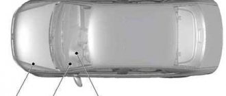
The T5 transporter began production in 2003 and has two fuse blocks installed on the left side of the engine compartment, two fuse and relay blocks in the central part of the dashboard, and an additional block under the front left seat. The location of the blocks in the car did not change until the model was discontinued in 2015.
T4 mounting blocks
Installation diagrams for fuses and relays, as well as their purpose, will be considered using the example of a 2002 Volkswagen Transporter T4 in the maximum possible configurations.
Blocks in the dashboard
The main unit is closed with a hinged plastic cover located to the left and below the steering column. The block has space for 12 relays, in fact there are fewer of them installed.
T4 main unit wiring diagram
Identification of fuses in them.
| Position | Purpose |
| A | Switching on the rear heating and ventilation system (optional) |
| B | Windshield wiper and rear window fluid supply system |
| IN | Engine control units |
| G | Additional elements of the ignition system |
| D | Reserve |
| E | Emergency stop indication |
| AND | Headlight glass washer |
| Z | Main wiper (windshield) |
| AND | Sound reminder about lighting elements that are not turned off |
| TO | Power supply to fog lights |
| L | Warning signal |
| M | Supplying power to the fuel pump |
Under the two rows of relays there are 22 fuses of various ratings to protect electrical equipment. A description of the purpose of these inserts can be found in the table.
| Position | Denomination, A | Chain |
| PR01 | 10 | Powering the low beam filament of the left headlight and adjusting the angle |
| PR02 | 10 | Same for the right headlight |
| PR03 | 10 | Rear registration plate and visor lights |
| PR04 | 15 | Rear window cleaning system |
| PR05 | 15 (20) | Windshield cleaning system (in case of optional heated injectors, the rating increases) |
| PR06 | 30 (20) | Microclimate system fan. Depending on the year of manufacture of the car, the denomination may be different. |
| PR07 | 10 | Side lights on the starboard side |
| PR08 | 10 | Likewise, only for the left side |
| PR09 | Reserve | Reserve |
| PR10 | 15 | Fog lights (front and rear) |
| PR11 | 10 | High beam thread on the left |
| PR12 | 10 | Same for the right side |
| PR13 | 10 | Warning signal |
| PR14 | 10 | Depending on the configuration - ABS system, automatic transmission control unit, central locking, electric windows and mirrors |
| PR15 | 10 | Engine control unit, speed detection and maintenance systems |
| PR16 | 15 | Lamps on the instrument cluster, glove box lighting, direction indicators |
| PR17 | 10 | Additional heater (optional) |
| PR18 | 20 | Engine and fuel pump operation system |
| PR19 | 10 | Cooling system control units (fans and additional pumps) |
| PR20 | 10 | Brake lights |
| PR21 | 15 | Radio and acoustics, diagnostic system, lighting |
| PR22 | 15 (10) | Cigarette lighter operation. Denomination may vary |
Under the main block there is an additional panel for 16 inserts of optional equipment.
Additional block T4
The purpose of the fuses is in it.
| Number | Denomination, A | Protected area |
| PR01 | 15 | Socket for additional equipment |
| PR02 | 15 | Trailer lighting |
| PR03 | 10 | Minibus sliding roof drive |
| PR04 | 20 (3) | Optional additional heater. In cars of different years, there may be a telephone in this place |
| PR05 | 10 | ABS system |
| PR06 | 3 (10) | Built-in telephone control unit. On later cars, this insert protects the ceiling light circuit |
| PR07 | 15 | Equipping a car for a taxi or an additional searchlight |
| PR08 | 10 | Additional roof fan |
| PR09 | 15 (25) | Radio, instrument cluster functions. On later cars - a two-tone signal |
| PR10 | 15 | Locking the locks |
| PR11 | 15 | Front seat heating system |
| PR12 | 30 | Electrically heated mirrors and rear window systems |
| PR13 | 3 (30) | Second telephone block. On later versions - climate control system |
| PR14 | 30 | Climate control system (rear cabin) |
| PR15 | 20 | Optional auxiliary heater |
Another block with the following relays is attached above the main unit:
- 1 — activation of the additional coolant pump (A);
- 2 — idle speed maintenance systems (B);
- 3 — turning on glow plugs for diesel (B);
- 4 - additional elements of the ignition system, not available on all gasoline engines (G);
- 5 - similar, but for cars with air conditioning (D).
Relay block on the left side of the panel
In addition to the relay, there are three fuses - one 30 A for the window drive system and two 15 A, which protect the engine control unit.
There is an additional relay block in the central part of the instrument panel.
Relay in the central part
The purpose of the parts is described in the table.
| Position | Purpose |
| A | Reserve |
| B | All-wheel drive connection block |
| IN | Activating the reverse warning lights |
| G | 150-amp generator circuit (automatic transmission) |
| D | 150 Amp Generator Circuit |
| E | Air intake mode switch for microclimate system |
| AND | Coolant supply to the additional interior heater |
| Z | Automatic climate control |
| AND | Rear heater fan |
| TO | Phone Speaker Mode Switch |
| L | Auxiliary heater control |
Under the seat
There is a small relay box under the driver's seat.
Placement of elements under the seat
The block contains two relays:
- connecting the second battery (A);
- ensuring the operation of the second heater (B).
Under the hood
There is a block installed under the hood, the diagram of which is shown in the photo.
Engine compartment block T4
The purpose of the fuses in it.
| Number | Denomination, A | Protected circuit |
| PR01 | 60 (50) | Heat of air heating plugs |
| PR02 | 50 | First cooling fan motor |
| PR03 | 50 | Similar to the second |
| PR04 | 50 | ABS system (unit itself) |
| PR05 | 110 | Generator protection (optional rated 150 and 175 A) |
| PR06 | 30 | Stability control |
| PR07 | 30 | Additional ESP block |
| PR08 | 5 | Stability control unit |
The author of the video, Dmitry Maznitsyn, disassembles the fuse box. This video shows the design of this unit well.
T5 mounting blocks
The electrical system of the next generation of Volkswagen Transporter T5 cars is much more complex and varied.
Motor block
In the engine compartment (the unit is designated in the diagrams as SA) on the restyled T5 2013, fuses are installed that are responsible for charging the batteries and distributing current from it.
Main fuse box T5
Purpose of inserts in this block.
| Number | Denomination, A | Protected circuit |
| PR01 | 175 (225) | Generator |
| PR02 | 125 | Battery power supply separator |
| PR03 | 50 and 100 | Double, designed to ensure operation and charging of a second battery |
| PR04 | 70 | Engine compartment circuit distribution |
| PR05 | 50 | Anti-lock braking system |
| PR06 | 60 and 50 | Glow plug system and air pump |
| PR07 | 100 | Cooling fan control |
| PR08 | 40, 50 and 100 | Power distributor |
| PR09 | 100 | Likewise |
| PR10 | Reserve | Reserve |
A large fuse box is installed on the left side of the engine compartment (indicated as SD on the car diagram).
Block under the hood of T5
It has inserts installed.
| Number | Denomination, A | Protected circuit |
| PR01 | 5 | Cooling fan start control |
| PR02 | 5 | Activation circuit for the additional electric pump in the cooling system |
| PR03 | 5 | Heated crankcase ventilation system |
| PR04 | Reserve | Reserve |
| PR05 | 15 | DSG transmission controls |
| PR06 | 30 | ABS control module |
| PR07 | 7,5 | Window washer pumps (only used since 2010) |
| PR08 | Reserve | Reserve |
| PR09 | 5 | Engine control system |
| PR10 | 5 (15) | Evaporative emission control valve (boost limiter) |
| PR11 | 30 | Headlight control |
| PR12 | 10 | Fuel pressure control system |
| PR13 | 10 | Left xenon lamp ignition unit |
| PR14 | 5 | Fuel pump control |
| PR15 | 10 | Reverse lamp activation |
| PR16 | 5 | Brake signals and air flow calculation system |
| PR17 | 5 | Activation keys for ESP and tire pressure checking systems |
| PR18 | 5 | Electric power steering system |
| PR19 | 5 | Clutch pedal limit switch |
| PR20 | 5 | Engine control system |
| PR21 | 5 | Exhaust gas recirculation system |
| PR22 | 10 | Ensuring the operation of injectors |
| PR23 | 10 | Right ignition unit for xenon lamps |
| PR24 | 5 | DSG transmission component control system |
| PR25 | 30 | Engine control units and ignition system |
| PR26 | 5 | Lamps in the right headlight |
| PR27 | 10 | Coolant pump after engine stop |
| PR28 | 10 | Audible warning signal (high tone) |
| PR29 | 5 | Lamps in the right headlight |
| PR30 | 20 | Fuel supply systems |
| PR31 | 15 | Heated lambda probes |
| PR32 | 5 (30) | Fuel pump relay or engine management system |
| PR33 | 5 | Controlling the activation of glow plugs and an additional coolant pump |
| PR34 | 5 | Managing network settings |
| PR35 | Reserve | Reserve |
| PR36 | 30 | Locking the starter when the engine is running |
The Avto-Blogger channel will tell you why fuses are needed in a car and how to check them with a multimeter. ru.
Since May 2011, the purpose of the inserts in the block has changed slightly. Changed items are listed below.
| Number | Denomination, A | Protected circuit |
| PR04 | 30 | Voltage stabilization system and radio (navigation) |
| PR10 | 5 (10 or 15) | Evaporative emission control valve (boost limiter). May have different denominations |
| PR13 | Reserve | Reserve |
| PR23 | Reserve | Reserve |
| PR25 | 30 (20) | Engine control units and ignition system. Variable valve timing system |
| PR26 | Reserve | Reserve |
| PR29 | Reserve | Reserve |
| PR35 | 5 (15) | Fuel pressure limiting system or battery monitoring unit |
| PR36 | 30 (5) | Starter interlock or diagnostic system |
Salon block
In the central part of the interior instrument panel there are two identical fuse blocks (SC at the bottom and SB at the top). Rate assignments may differ on cars produced before May 2004 and after. The next change in the location of the inserts occurred in May 2011 during the release of the restyled T5 model.
General view of the T5 cabin section (the second part is identical)
Option for placing fuses in the upper section until May 2004.
| Number | Denomination, A | Purpose |
| PR01 | 30 | Microclimate system |
| PR02 | 5 | Steering angle control system |
| PR03 | 10 | Multi-function block circuit |
| PR04 | 10 | Headlight range control |
| PR05 | 15 | Lamps in the left headlight |
| PR06 | 15 | Likewise |
| PR07 | 15 | Interior lighting |
| PR08 | 5 | Machine electrical diagnostics |
| PR09 | 15 | Brake light limit switch |
| PR10 | 5 | Window cleaning control |
| PR11 | 5 | Illuminated buttons on the panel |
| PR12 | 15 | Cigarette lighter |
| PR13 | 5 | Turning off the brake lights |
| PR14 | 30 | Additional heater |
| PR15 | 7,5 | Air conditioner control |
| PR16 | 5 | Multi-function block circuit |
| PR17 | 5 | Turning on the fog lights |
| PR18 | 5 | Instrument cluster |
| PR19 | 5 | Radio tape recorder |
| PR20 | 5 | Dimensions on the left side |
| PR21 | 5 | Dimensions on the starboard side |
| PR22 | 10 | Diagnostic system |
| PR23 | 25 | Trailer electrical |
| PR24 | 5 | Steering wheel rotation sensor |
| PR25 | 5 | Turning on the air conditioner |
| PR26 | 5 | Differential lock |
| PR27 | 15 | Lamps in the right headlight |
| PR28 | 15 | Likewise |
| PR29 | Reserve | Reserve |
| PR30 | 10 | Injector heating and rear window cleaning |
| PR31 | 30 | Warning signal |
| PR32 | 25 | Cleaning the windshield |
| PR33 | 15 | Navigation |
| PR34 | 25 | Automatic transmission control |
| PR35 | 5 | Instrument lighting |
| PR36 | 25 | Direction indicators |
The Auto Electrician HF channel will tell you how to check the functionality of the fuse.
Designation of the second (lower) part of the block.
| Number | Denomination, A | Purpose |
| PR01 | 15 | Accessory socket 1 |
| PR02 | 5 | Standard anti-theft system |
| PR03 | 5 | Additional climate control fan |
| PR04 | 15 | Accessory socket 2 |
| PR05 | 15 | Accessory socket 3 |
| PR06 | 5 | Oil level checking system |
| PR07 | 10 | Fan on roof panel |
| PR08 | 5 | Parktronic |
| PR09 | 5 | Steering Column Control |
| PR10 | 30 | Radio tape recorder |
| PR11 | 20 | Electric door sliding |
| PR12 | 5 | Additional heater |
| PR13 | 5 | Steering wheel buttons |
| PR14 | 5 | Telephony |
| PR15 | 5 | Automatic transmission control units |
| PR16 | 5 | Radio and navigation |
| PR17 | 5 | Turning on the air conditioning system |
| PR18 | 5 | Likewise |
| PR19 | 5 | Dimming rear view mirror |
| PR20 | 10 | Heated mirrors |
| PR21 | 5 | Standard anti-theft system |
| PR22 | 5 | Turning on the air conditioning system |
| PR23 | 5 | Additional heater |
| PR24 | 5 | Camping systems |
| PR25 | 15 | Heated seats |
| PR26 | 10 | Tachograph |
| PR27 | 15 | Fog lights |
| PR28 | 5 | Door mirror adjuster |
| PR29 | 25 | Additional heater |
| PR30 | 5 | Likewise |
| PR31 | 25 | Sliding sunroof |
| PR32 | 20 | Headlight washer system |
| PR33 | 5 | Tachograph |
| PR34 | 20 | Additional vacuum pump |
| PR35 | 10 | Multi-function block circuit |
| PR36 | 15 | Additional equipment at the rear |
Since June 2004, this block has changed slightly. The table shows only the changed positions of the upper part of the block.
| Number | Denomination, A | Purpose |
| PR01 | 25 (30) | Microclimate system |
| PR10 | 10 | Window cleaning control |
| PR11 | 5 | License plate light |
| PR13 | 5 | Airbag control |
| PR22 | 10 | Diagnostic system, passenger airbag deactivation |
| PR23 | 5 | Starter relay (for manual transmission) |
| PR26 | 30 | Turning off the headlights |
| PR29 | 5 | Tailgate open alarm |
The lower section has changed more.
| Number | Denomination, A | Purpose |
| PR01 | 25 | Trailer electrical equipment |
| PR04 | 10 | All-wheel drive transfer case control |
| PR05 | 10 | Optional equipment |
| PR12 | 5 (10) | Disabling the brake light |
| PR17 | 7,5 | Interior lighting |
| PR18 | 5 | Air conditioning system |
| PR24 | 7,5 | Interior lighting |
| PR25 | 15 (25) | Heated seats |
| PR34 | 15 | Accessory socket 1 |
| PR36 | 5 | Additional camping equipment |
Relay box under the hood
A relay block is installed in the engine compartment. There are two different types of this node.
Block of the first type Block of the second type
The purpose of the relay can be clarified in the table.
| Type 1 | Type 2 | Purpose |
| A | A | Manual air conditioner control |
| B | B | Fuel pump circuit activation |
| IN | IN | Turning on the air purge pump |
| G | G | Ignition circuit |
| D | D | Fuel pump circuit activation |
| E | E | Automatic air conditioning control |
| AND | — | Automatic transmission control |
| AND | Reserve | Power steering |
| Z | Z | Additional coolant pump |
| — | AND | Starter activation |
Block under the seat
Another block is located under the seat and can be found in four versions. The diagram is shown in the photo.
First block type
Arrangement of elements in a block.
| Number | Denomination, A | Description |
| A | — | Control relay for operation of the second battery |
| B-Z | Reserve | Reserve |
| PR01 | 40 | Electrical circuits in the right sliding door |
| PR02 | 25 | Additional heater electrical systems |
| PR03 | 40 | Electrical circuits in the left sliding door |
| PR04 | 5 | Antenna |
| PR05 | 80 | Second battery charging relay |
The block diagram of the second type is shown in the photo.
Second type
Decoding the elements in the block.
| Number | Denomination, A | Description |
| A and B | Reserve | Reserve |
| IN | — | Control relay for operation of the second battery |
| G and D | — | Special equipment |
| PR01 | 5 | Camping systems management |
| PR02 | 10 | Accessory power socket |
| PR03 | 5 | Tank water pump (camping) |
| PR04 | 10 | Illumination lamps |
| PR05 | 30 | Additional camping equipment |
| PR06 | 40 | Roof lift drive |
| PR07 | 5 | Antenna |
| PR08 | 25 | Additional heater electrical systems |
| PR09 | 30 | Automatic operation of the microclimate system |
| PR010-12 | Reserve | Reserve |
| PR013 | 40 | Electrical circuits in the right sliding door |
| PR014 | 80 | Second battery charging relay |
The diagram of the third type of block can be seen in the photo.
Third block type
Purpose of parts in this block.
| Number | Denomination | Description |
| A and B | Reserve | Reserve |
| IN | — | Control relay for operation of the second battery |
| Ms. | Reserve | Reserve |
| PR01 | 5 | Antenna |
| PR02 | 25 | Additional heater electrical systems |
| PR03 | 10 | Automatic operation of the microclimate system |
| PR04-6 | Reserve | Reserve |
| PR07 | 40 | Electrical circuits in the right sliding door |
| PR08 | 80 | Second battery charging relay |
Scheme of the fourth type of block.
Fourth option
The purpose of the fuses in it.
| Number | Denomination | Description |
| A | Reserve | Reserve |
| B | — | Control relay for operation of the second battery |
| V-D | — | Special equipment |
| PR01 | 15 | Circuit 1 for accessories |
| PR02 | 15 | Circuit 2 for accessories |
| PR03 | 15 | Circuit 3 for additional equipment |
| PR04 | 15 | Chain 4 for accessories |
| PR05 | 5 | Antenna |
| PR06 | 25 | Additional heater electrical systems |
| PR07 | 30 | Automatic operation of the microclimate system |
| PR08-10 | Reserve | Reserve |
| PR011 | 40 | Electrical circuits in the right sliding door |
| PR012 | 80 | Second battery charging relay |
Since 2009, this block has become much more complex.
Block on T5 GP
It includes the following components.
| Number | Denomination, A | Purpose |
| PR01 | 5 | External socket or additional equipment (vehicles for special services) |
| PR02 | 3 | Likewise |
| PR03 | 15 (5) | Likewise |
| PR04 | 15 | Likewise |
| PR05 | 5 | Likewise |
| PR06 | 25 | Likewise |
| PR07 | 15 (30) | Internal socket or 220 Volt inverter |
| PR08 | 20 (25) | Additional heater electrical systems |
| PR09 | 25 (30) | Fan for supplying outside air to the rear of the cabin |
| PR10 | 15 (30) | Autonomous temperature maintenance (the second rating has been installed since the summer of 2010) |
| PR11 | 15 | Cigarette lighter |
| PR12 | 5 | External socket or additional equipment (vehicles for special services) |
| PR13-15 | Reserve | Reserve |
| PR16 | 30 | On-board charger |
| PR17 | 30 | Hydraulic roof drives |
| PR18 | 10 | Interior and kitchen lamps (camper) |
| PR19 | 10 | Fridge |
| PR20 | 5 | Water tank pump |
| PR21 | 5 | Camper equipment management |
| PR22 | 15 | Socket 1 |
| PR23 | 15 | Socket 2 |
| PR24 | 10 (15) | Cargo compartment fan or power outlet 3 |
| PR25 | 15 | Trailer equipment |
| PR26 | 20 | Trailer equipment |
| PR27 | 20 | Trailer equipment |
| PR28 | 7,5 | Rear view camera |
| PR29 | Reserve | Reserve |
| PR30 | 5 | Amplifier (until May 2010, then reserve) |
| PR31 | Reserve | Reserve |
| PR32 | Reserve | Reserve |
| PR33 | 15 | Driver's seat lumbar support |
| PR34 | 40 | Electrical circuits in the right sliding door |
| PR35 | 80 | Second battery charging relay |
| PR36 | 40 | Electrical circuits in the left sliding door |
| PR37 | 40 | Additional supply fan |
| PR38 | 40 | External socket or additional equipment (vehicles for special services) |
| PR39 | Reserve | Reserve |
Scheme
Let's consider the layout and description of the elements of each model separately.
Model T5
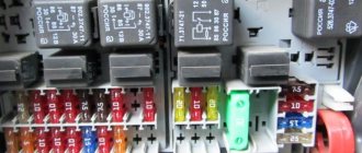
As mentioned above, the T5 minibus model is equipped with several control devices for electrical appliances. One of them is in the engine compartment. Its location and purpose of components are described below.
The fuse box is located in the engine compartment next to the battery
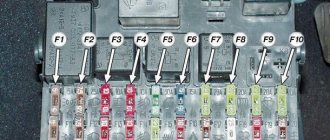
Description of the block parts located in the engine compartment
Description of the block parts located in the engine compartment
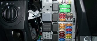
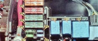
Below is a diagram of the unit located inside the car in the center console area, as well as a table describing its components.
Block with elements located in the center of the console in the cockpit
Descriptive table of the power supply, which is located inside the minibus
Descriptive table of the power supply, which is located inside the minibus
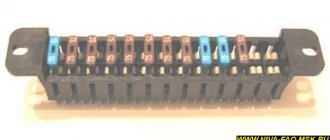
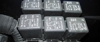
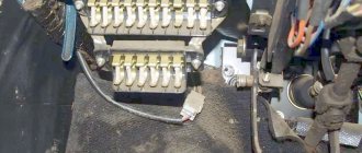
In addition, some modifications of Volkswagen T5 minibuses are equipped with another device. The relay block is located on the instrument panel immediately behind the power supply. Below you will find its diagram and description.
Diagram of a relay device located behind the power supply on the instrument panel
High power fuse diagram Volkswagen Transporter T5
Description
| one | (175 / 225A) Generator |
| 2 | (125A) Battery power distribution, auxiliary ignition relay, driver door control module, passenger door control module, rear window defroster, terminal X relay, individual fuses |
| 3 | (50A / 100A) Charging system (with additional battery), rear left power door control unit (some models), rear right power door control unit (some models), charging system divider relay (with additional battery) |
| 4 | (125A) Battery power distribution (70A) Positive connection in engine compartment wiring |
| 5 | (50 A) Battery power distribution (some models), separate fuses |
| 6 | (60A) Glow plug relay (50A) Exhaust air pump motor |
| 7 | (70/80/100A) Cooling fan motor(s) |
| eight | (40/50/100A) Cooling Fan Motor(s), Separate Fuses |
| nine | (100A) Battery power distribution, ignition switch |
Transmission, clutch
Elimination of backlash in the input shaft of 6-speed gearboxes 02N, 02M, 02Q, 02Z and 0A5 (rus.)
Photo report Signs of play: Poor clutch operation, difficulty disengaging first gear and reverse gear. In some cases, the clutch pedal does not return. The problem mainly occurs after people drive with a rattling flywheel.
7-speed dual clutch transmission 0BT T5, modification 2010 (rus.)
Device and principle of operation. Self-education program manual. Contents: Introduction, Gearbox selector, Gearbox design: Multi-disc clutch, Gearbox shafts, Force closure of secondary shaft gears, Parking lock, Power flow distribution, Reverse gear. Mechatronic unit, Electro-hydraulic control unit, Transmission hydraulic circuit, Transmission control system, Maintenance.
Blocks in the cabin
Main unit
Photo - an example of the entire block
Upper section diagram
Designation
- 5A - 10-pin header / 6-pin header
- 3A - 10-pin connector
- 5/15A – 10-pin connector or alarm data recorder
- 15A - 10 pin connector
- 5A - 10-pin connector
- 25A - 6-pin connector
- 15/30 - 12V socket, voltage converter
- 20 / 25A - Heater control unit (heater)
- 25 / 30A – Supply fan
- 15 / 30A – Air conditioning
- 15A - Cigarette lighter
- 5A - 10-pin header / 6-pin header
- Local relay
- Local relay
- Local relay
- 30A - on-board charger
- 30A - Roof hydraulic unit
- 10A - Light ceiling lamps
- 10A - Refrigerator compartment
- 5A - Water pump
- 5A - Control panel for van equipment
- 15A - 12V socket
- 15A - 12V socket
- 10A - Roof fan or 12V socket
- 15A - Trailer recognition control unit
- 20A - Trailer recognition control unit
- 20A - Trailer recognition control unit
- 7.5A - Trailer recognition control unit
- To book
- 5A - Voice amplifier control unit
- To book
- To book
- 15A - Driver's seat lumbar support
- 40A - Right sliding door control unit
- 80A — Control unit for recharging the second battery
- 40A - Left sliding door control unit
- 40A — Supply fan
- 6-pin connector
- To book
General arrangement of control units
Designation
| 1 | ABS electronic control unit |
| 2 | Air conditioning control unit - in the heater control panel |
| 3 | Air conditioning control unit (rear) - in the heater control panel |
| 4 | Antenna unit - if available |
| 5 | Side impact sensor, driver's side |
| 6 | Side impact sensor, rear left |
| 7 | Side impact sensor, passenger side |
| 8 | Side impact sensor, rear right |
| 9 | Anti-theft control unit |
| 10 | Anti-theft alarm horn - intake system resonator |
| 11 | Audio Output Amplifier - Under Front Right Seat - If Equipped |
| 12 | Auxiliary Battery 1 - Under Front Left Seat - If Equipped |
| 13 | Extra Battery 2 (RV) - in kitchen cabinet |
| 14 | Additional heater control unit (Air Top 3500) - under the body, on the right - if equipped |
| 15 | Additional heater control unit (Thermo Top) - under the body, on the left - if equipped |
| 16 | Accumulator battery |
| 17 | Camping equipment control unit (caravan) |
| 18 | Diagnostic connector (DLC) |
| 19 | Diagnostic unit - instrument panel |
| 20 | Driver's door electrical control unit |
| 21 | Rear Left Door Electrical Control Module (Power Sliding Door) - Left Pillar |
| 22 | Passenger door electrical control unit |
| 23 | Right Rear Door Electrical Control Module (Power Sliding Door) - Right Pillar |
| 24 | ESP control unit (includes acceleration sensor, lateral movement sensor) |
| 25 | Roof lift mechanism control unit (van) |
| 26 | Electronic Engine Control Module - Near the fuse/relay box in the engine compartment 1 |
| 27 | Cooling Fan Motor Control Module 1 - Suspension (Left Front) |
| 28 | Cooling fan motor control unit 2 - in cooling fan motor 2 - if installed |
| 29 | Fuse/Relay Box, Engine Compartment 1 |
| 30 | Fuse/Relay Box, Engine Compartment 2 |
| 31 | Fuse/relay box, engine compartment 3 |
| 32 | Fuse/Relay Box, Instrument Panel 1 - Central Instrument Panel |
| 33 | Fuse/Relay Box 2, Instrument Panel - Below Fuse/Relay Box 1, Instrument Panel |
| 34 | Fuse/Relay Box, Instrument Panel 3 - Behind Fuse/Relay Box, Instrument Panel 1/2 |
| 35 | Fuse/Relay Box, Instrument Panel 4 - Behind Fuse/Relay Box, Instrument Panel 1/2 |
| 36 | Fuse/Relay Box, Left Seat - Under Seat |
| 37 | Additional fuse 1 (differential lock switch, rear 10A) - left front pillar |
| 38 | Additional fuse 2 (auxiliary heater 30A) - under the left seat |
| 39 | Additional fuse 3 (door power control unit, left rear 40A) - under the left seat (some models) |
| 40 | Heater blower motor resistor 1 - near the rear heater blower motor |
| 41 | Heater blower motor resistor 2 - near rear heater blower motor - if equipped |
| 42 | Beep 1 |
| 43 | Beep 2 - if present |
| 44 | Immobilizer control unit - instrument cluster |
| 45 | Immobilizer ring antenna - near the ignition switch |
| 46 | Instrument cluster control unit - instrument panel |
| 47 | Telephone control unit - behind the glove compartment |
| 48 | Multifunction control unit 1 - functions: Automatic transmission (automatic transmission), charging system (with additional battery), cruise control, door/hood switch contact recognition, electrical load control, power windows, fuel pump, headlight washers, rear mirror defroster door view, rear window defroster, hazard warning lights, windshield defroster, horn, turn signals, instrument cluster lights, interior lights, automatic wipers, reverse lights, starter, sunroof, light switch, windshield washer, wiper windshield |
| 49 | Multifunction control unit 2 - functions: Anti-theft system, central locking, electric door mirrors, electric sliding door, electric windows, sunroof |
| 50 | Navigation system control unit - in the navigation system display |
| 51 | Ambient temperature sensor |
| 52 | Parking system control unit |
| 53 | Driver seat heating control unit |
| 54 | Passenger seat heating control unit |
| 55 | Steering wheel position sensor - if equipped |
| 56 | Electric sunroof control unit |
| 57 | Electronic control unit SRS |
| 58 | Rear door open/close drive control unit - left "D" pillar - if equipped |
| 59 | Traffic Information System Control Module - Under Dashboard |
| 60 | Traffic information control unit (alternative position) - under the instrument panel |
| 61 | Transfer case control unit (with 4WD) - rear final drive |
| 62 | Electronic transmission control unit (automatic transmission) - near the engine control unit |
| 63 | Voice synthesizer - under the front right seat - if equipped |
| 64 | Vehicle speed sensor - gearbox (some models) |
Removal and replacement process
Required tools: flat screwdriver, keys 10, 14.
Engine compartment
The procedure is as follows:
- Remove the negative terminal after turning off the ignition.
- While pressing the latches, remove the top cover from the unit.
- Remove the broken fuse or relay. If the power multi-function fuse at the end has blown, unscrew the nuts with a 14mm wrench, remove the wires from the studs and, pressing the plastic clips, pull out the part. Completely replaced.
- Install a new element, having first eliminated the source of the short circuit.
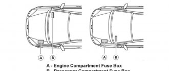
Volkswagen Caravelle - fuse box diagram
Year of manufacture: 2004, 2005, 2006, 2007, 2008, 2009, 2010, 2011, 2012, 2013 and 2014.
T6 from 2015
The cigarette lighter (socket) fuse on the Volkswagen Caravelle is fuse 12 in the passenger compartment fuse box.
The location of the boxes in the Volkswagen Caravelle (Multivan) T5 and T6 is similar. However, their picture is different.
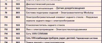
Decoding fuses VW T5 2004-2009 before restyling
Hi all!
I encountered such a small problem as:
the fuse for the interior lighting had blown
(
I installed my favorite LEDs
), but I couldn’t find it from the pictures.
I had to search the entire Internet. I found it on a third-party site, but everything is written in such a way that you won’t understand. In short, bookmark this reminder!
1 - (25A/30A) Heater/air conditioner (some models) 2 - (5A) Steering wheel position sensor 3 - (10A) Multifunction control unit 1 4 - (10A) Headlight range control 5 - (15A) Left headlight bulb 6 - ( 15A) Left headlight lamp 7 - (15A) Multifunction control unit 1 (interior lamp) 8 - (5A) Diagnostic connector (DLC) 9 - (15A) Brake light switch (brake pedal position sensor) 10 - (10A) Windshield wiper/ rear window wiper 11 — (5A) License plate light 12 — (15A) Cigarette lighter 13 — (5A) SRS electronic control unit 14 — (30A) Auxiliary heater heater/air conditioning 15 — Air conditioning 16 — (5A) Multifunction control unit 1 17 — (5A) Rear fog lights 18 — (5A) Instrument cluster control unit 19 — ^Audio system, instrument cluster control unit, multifunction control unit 1, navigation system, special vehicle equipment 20 — (5A) Front marker-left, left stop- signal, tail light - left 21 - (5A) Front marker - right, right brake light, tail light - right 22 - (10A) Passenger airbag off indicator, diagnostic connector (DLC), instrument cluster control unit 23 - (5A ) Starter relay (some models with manual transmission) 24 - Steering wheel position sensor 25 - air conditioning 26 - (30A) Headlight switch 27 - (15A) Right headlight lamp 28 - (15A) Headlight high beam indicator, right headlight 29 - Signal relay tailgate 30 - (10A) Windshield washer nozzle heaters, rear window wiper motor 31 - (30A) Multifunction control unit 1 (horn) 32 - (25A) Multifunction control unit 1 (windshield wiper motor) 33 - (15A) ) Audio system, navigation system, traffic information system control unit 34 - (25A) Automatic transmission control system, fuse/relay box, engine compartment 1 35 - (5A) Instrument cluster illumination 36 - (25A) Multifunction control unit 1 (turn indicators)
Article on the topic: Where is the Volkswagen Touran made?
1 - (25A) Trailer electrical connector 2 - (5A) Anti-theft system 3 - (5A) Auxiliary air conditioner/heater fan, left, auxiliary air conditioner/heater fan, right 4 - (10A) Transfer case control unit 5 - (10A) Connector additional equipment (some models) 6 - (5A) Engine oil sensor 7 - (10A) Roof fan 8 - (5A) Parking system 9 - (5A) Steering column control unit 10 - (30A) Audio system 11 - (20A) ) Anti-theft alarm horn, multi-function control unit 2, power sliding door, rear door opener/close control unit 12 - (5A/10A) Brake light cut-off relay 13 - (5A) Cruise control main switch, multi-function control on steering wheel 14 — (5A) Telephone 15 — (5A) Automatic transmission 16 — (5A) Audio/navigation system, telephone 17 — (7.5A) Multifunction control unit 1 (interior lamp) 18 — (5A) Air conditioning (some models) 19 - (5A) Auto-dimming interior rearview mirror 20 - (10A) Multifunction control unit 1 (heated door mirrors) 21 - (5A) Anti-theft system 22 - (5A) Air conditioning 23 - (5A) Auxiliary heater 24 — (7.5A) Interior lamps 25 — (15A/25A) Heated seats 26 — (10A) Tachograph (if equipped) 27 — (15A) Fog lights 28 — (5A) Rearview mirror adjustment switch, rear mirror heaters type on the doors 29 — (25A) Additional heater 30 — (5A) Additional heater 31 — (25A) Sunroof 32 — (20A) Headlight washers 33 — (5A) Tachograph (if equipped) 34 — (15A) Additional equipment power supply connector 3 (rear) 35 - (10A) Multifunction control unit 1 (reversing light(s), with automatic transmission) 36 - (5A) Camping equipment control unit, special vehicle equipment
Article on the topic: How much horsepower does a Volkswagen Touareg have?
1 0 (5A) Cooling fan motor(s) 2 - (5A) Coolant pump relay 3 - (15A) Air conditioning 4 - (30A) Anti-lock brake system (ABS) 5 - (15A) Automatic transmission 6 — (30A) Anti-lock brake system (ABS) 7 — (5A) Cooling fan motor control unit 2 (some models) 8 — (15A) Engine control 9 — (5A) Engine control, main ignition circuit relay 10 — (5A) Coolant Pump Relay, Engine Management System 11 - 12 - Engine Control 13 - (10A) Engine Control 14 - Engine Control 15 - (10A) Reverse Light Switch 16 - Engine Control 17 - (5A) Anti-Lock Brake System (ABS) 18 — (5A) Multifunction control unit 1 19 — (5A) Brake light switch (brake pedal position sensor), clutch pedal position sensor 20 — Engine control 21 — (5A) Engine control 22 — (10A) Engine control 23 — (25A ) Automatic Transmission 24 - (5A) Automatic Transmission 25 - (25A) Engine Control 26 - (25A) Engine Control 27 - (5A) Coolant Pump Relay 28 - (15A) Horn (Some Models) 29 - (20A ) Brake booster vacuum pump 30 - (15A) Auxiliary A/C/Heater pump relay (some models), fuel pump (some models), fuel pump relay (some models) 31 - (15A) Engine management 32 - (30A) Engine management 33 — (5A) Coolant pump relay, engine control, glow plug relay 34 35 — (10A) Engine control 36 — (25A/40A) Starter relay (some models) ——————————
Article on the topic: How many liters of gasoline in a Volkswagen polo
If you find it useful, please like it. otherwise I’m really tired of this article)))
Thank you for your attention, and I hope you never need this article! )