Volkswagen Transporter T4 - represents the 4th generation of the legendary “transporter” series. This model was produced in 1990, 1991, 1992, 1993, 1994, 1995, 1996, 1997, 1998, 1999, 2000, 2001, 2002 and 2003 with diesel and gasoline engines with different wheelbase options: short and long, and with different roof height.
Also on the T4, Volkswagen continued its line of luxury models Caravelle, California and Multivan.
In our material we will show the location of all electronic control sides and a detailed description of the purpose of fuses and relays of the Volkswagen T4 with diagrams of the blocks in which they are located and their photographs. Note the fuse responsible for the cigarette lighter.
The actual purpose of the fuses may differ from those presented and depends on the year of manufacture and the level of electrical equipment.
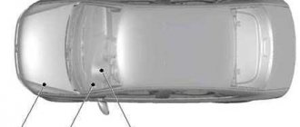
Block in the cabin
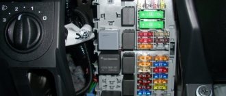
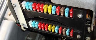
Almost all inserts and fuses are mounted inside the car. There is a breakdown into 4 parts to reduce the size of the block and simplify its design.
Main unit
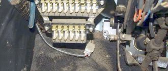
The installer is mounted in the driver's feet; to access it, a special panel must be opened. The fuses and relays themselves will appear behind it. When servicing the vehicle, you may have to remove the module. Some inserts are installed on the back of the device.
Additional fuse block
Auxiliary compartments are installed above and below the main module. This makes repair work much easier and faster. Here, mainly elements responsible for auxiliary electrical equipment are installed.
Additional relay block 1, 2
Mounted in remote locations. The relays are installed in the dashboard, strictly in the center. To access the device, open the installer's cover.
The second auxiliary module is located under the driver's seat. Here are the main protective elements of power circuits and energy-intensive equipment.
Scheme
Let's consider the layout and description of the elements of each model separately.
Model T5
As mentioned above, the T5 minibus model is equipped with several control devices for electrical appliances. One of them is in the engine compartment. Its location and purpose of components are described below.
The fuse box is located in the engine compartment next to the battery
Description of the block parts located in the engine compartment
Description of the block parts located in the engine compartment
Below is a diagram of the unit located inside the car in the center console area, as well as a table describing its components.
Block with elements located in the center of the console in the cockpit
Descriptive table of the power supply, which is located inside the minibus
Descriptive table of the power supply, which is located inside the minibus
In addition, some modifications of Volkswagen T5 minibuses are equipped with another device. The relay block is located on the instrument panel immediately behind the power supply. Below you will find its diagram and description.
Diagram of a relay device located behind the power supply on the instrument panel
High power fuse diagram Volkswagen Transporter T5
Description
| one | (175 / 225A) Generator |
| 2 | (125A) Battery power distribution, auxiliary ignition relay, driver door control module, passenger door control module, rear window defroster, terminal X relay, individual fuses |
| 3 | (50A / 100A) Charging system (with additional battery), rear left power door control unit (some models), rear right power door control unit (some models), charging system divider relay (with additional battery) |
| 4 | (125A) Battery power distribution (70A) Positive connection in engine compartment wiring |
| 5 | (50 A) Battery power distribution (some models), separate fuses |
| 6 | (60A) Glow plug relay (50A) Exhaust air pump motor |
| 7 | (70/80/100A) Cooling fan motor(s) |
| eight | (40/50/100A) Cooling Fan Motor(s), Separate Fuses |
| nine | (100A) Battery power distribution, ignition switch |
Fuse and relay diagram
The fuse panel wiring diagram is not made in a single design. A system that is too complex is difficult to read and difficult for readers to understand. For the convenience of users, the decoding and description of all FV T4 fuses produced in 1992, 1995 and 1997 are given separately.
EMM T4 block
An additional area of body electronics is installed in the car's interior. The device is responsible for controlling basic mechanisms and electrical appliances. All electrical control, switches and indicator lights come from here.
ABS unit
The traction control system is protected through fuse element F14. The power line of the device runs here. The indicator part on the device is mounted through fuse F16. Split protection ensures complete system security.
Window lifters
A power window fuse – F14 – is also installed nearby. There are no drive relays in the circuit. The relays are mounted directly next to the drive.
central locking
The above element No. 14 is also responsible for the operation of the system. There are no relays in the circuit.
Glow plug fuses and relays
Diesel cars are equipped with monitoring systems. The T4 design has a separate heating element control module. The device circuit relay is located in a special compartment, along with the rest of the relays.
The spark plugs for cylinders 1, 2, 3 and 4 are protected by power fuse F1, installed under the hood.
Air conditioner relays and fuses
Elements F14, installed in the lower left part of the instrument panel, are responsible for the operation of the clutch. The outside air intake system is activated via relay R6.
This division is typical for most modifications. In some cases, there are additional protections in the car interior and a special thermistor at the fresh air inlet from overboard.
Signal
The sound signal system in the car is quite simple. There is a standard fuse F13 and power relay No. 11.
Cigarette lighter fuse
Insert F22 of the main unit under the dashboard is responsible for the element and an additional socket in the rear of the car (if equipped).
Cooling Fan
The cooling system of the power plant consists of two fans. Fuse F19 from the main unit is responsible for powering the electronic unit of the cooler control system.
The forced fluid circulation pump is turned on by relay insert R1 from the main module installed in the cabin. The fans themselves are protected by inserts F2 and 3. Repairing the main fan switching circuit is complicated - you will need to check several individual elements.
Generator fuse and relay
Using the 2001 modification as an example, the machine's generator set control system is examined separately. The power circuits of the device pass through relays No. 7 and 8 of the main unit. There is also a voltage regulator fuse F5.
This arrangement of elements is relevant for versions:
- T424;
- T48;
- T46;
- T419.
In other configurations, the installation locations of parts may differ.
Heater
On most cars, the heater fan control circuit is protected by fuse F6. The cooler operation circuits at low speeds are protected through relay No. 4. For maximum rotation speed there is a separate switch R1. In some configurations this may be relay R2 of the interior unit.
Rear heater
The car comes with a separate heater installed from the factory. Depending on the configuration, fuse F14 or 15 may be responsible for turning on the fan. The devices are controlled by fuse link F4.
The relays are located at positions R3/4 for low and high fan speed respectively.
Main relay T4
It is a separate unit where the main parts of the engine compartment electronics are concentrated. The device controls all important processes in the machine and is not serviced. The manufacturer made the module non-repairable.
Relay 109: what it is responsible for
Ensures that the electronic engine management system is turned on. It supplies power to sensors installed in the cylinder head and cylinder block. To find the relay assembly, you do not need an article number. A regular insert sold in every store will do here.
Number of turn relay T4
The standard fuse is installed under number F16. Relays and lamp breakers are placed separately under the instrument panel. You can recognize the exact location of the parts by a characteristic clicking sound.
38 VW T4 relays
These are breakers for the additional pump that supplies antifreeze to the rear heater and are installed next to the other switches inside the unit.
Starter relay
The engine starting system is equipped with a standard pull-in relay. The device is located on the body of the electric motor. The engine blocking relay after starting the internal combustion engine is located under number F36.
If a part burns out, you can use an analogue from Valeo.
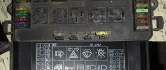
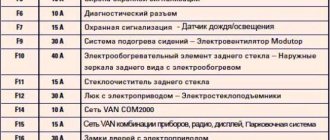
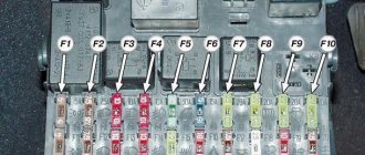
Model t4
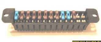
Location of power components in Volkswagen T4
| Serial number | What is he responsible for? |
| one | Provides low beam operation and changes the range parameters of the left headlight. |
| 2 | it is also responsible for the operation of the flashlight bulbs and is designed to adjust the range parameters of only the right headlight. |
| 3 | This fuse box is responsible for the operation of the instrument panel and license plate LED lights. |
| 4 | Without this part, the wipers will not work. |
| 5 | Provides operation of wipers, as well as windshield and rear window washers. |
| 6 | Responsible for the performance of the heating and air conditioning systems of the engine. |
| 7, 8 | Provides operation of side lights, as well as left and right brake lights. |
| nine | The operation is carried out by a device designed to heat the rear window and side mirrors. |
| 10 | Responsible for the operation of fog lights. |
| 11, 12 | Without these fuses, the high beams will not work. In addition, the high beam warning lamp will stop working. |
| 13 | Without this part, the horn will not work. In addition, the radiator fan will also stop working. |
| 14 | This element performs several functions at once:
|
| fifteen | Ensures the functionality of the minibus engine electronics. |
| sixteen | This number allows you to turn on LED instrument panel lighting and glove box lighting. |
| 17 | This element ensures the operation of the direction indicators. |
| 18 | Part No. 18 provides:
|
| 19 | Without this part, the operation of the radiator fan and the air conditioning system, that is, the air conditioner, is impossible. |
| 20 | If this part fails, the brake light bulbs will not work and neither will the speed control sensor. |
| 21 | Ensures the functioning of light bulbs in the interior of the minibus, as well as in the trunk. In addition, this part is responsible for the operation of the interior clock, central locking and radio. |
| 22 | Ensures the functionality of the cigarette lighter. |
This was a straightforward description of the fuse box. They are arranged in a row at the bottom of the diagram. Now let's talk about the purpose of the relay. Components that are not used will not be described in the table.
| Number | Description |
| one | This relay ensures the operation of the air conditioning compressor. |
| 2 | Rear window wiper, as well as its washing machine. |
| 3 | Injection and ignition system. If a component fails, the engine will not be able to start. |
| 4 | This relay reduces the load on terminal X of the ignition switch. |
| 6 | Device for interrupting direction indicators and light signals. |
| 7 | Headlight washer motor. |
| eight | Without it, the windshield washer mechanism will not work. |
| nine | Responsible for the functionality of the mechanism that warns the driver about unfastened seat belts. |
| 10 | Ensures the functionality of the fog lamp bridge. |
| eleven | Without this component the horn will not work. |
| 12 | Responsible for the operation of the diesel pump and system heating device before starting the engine. |
| 13 | Ensures the operation of preheater and starter blocking devices. |
| 14,16 | These components allow the ABS system to function. |
| fifteen | If any element is broken, the ABS hydraulic pump will not work. |
| 17 | The ABS valves and pump will stop working if component #17 fails. |
| 18 | Electric adjustment mechanism for the front seats. |
| 20 | Responsible for the performance of the starter, as well as the reversing lights. |
| 21 years old | Lambda probe heating device. |
In addition, there is an additional relay in the engine compartment. In particular, an element of the heating system of a diesel internal combustion engine is located on the partition above the brake booster.
Removal and replacement procedure
Any Transporter minibus car owner will sooner or later be faced with the need to replace fuses. Actually, like the owner of any other car. No one is immune from this, so in any case, replacing fuses in a motorist’s everyday life is inevitable. To learn how this process works, we provide you with detailed instructions for replacing components.
So, if a voltage-powered device in your car fails, first of all you need to check the serviceability and condition of the fuse.
And rightly so, because you won't buy a new fuel pump if you just need to replace a fuse. For this you will need a screwdriver. And not in all cases.
In some car models, the power supply is hidden behind a plastic plug that is secured with screws, but is usually held in place only by a latch.
All work on replacing parts of the power supply must be carried out with the battery turned off to avoid short circuits:
- Open the hood and remove the negative terminal from the battery.
- you need to decide on which power supply you need to replace the components to fix the problem. In any case, open the desired lock and, guided by the diagrams above or the markings on the back of the power supply, find the faulty element.
- You will find special tweezers in the power supply housing. It is intended directly for disassembling fuses. Disassemble the burnt component and inspect it. If its body is slightly burnt or the fuse wire in the part itself is already broken, then it must be urgently replaced. It will be more difficult with a relay - it is almost impossible to visually determine its malfunction. Only occasionally do the bayonets of the relay, which is connected to the socket, burn slightly. But without ringing the relay and disassembling it, it is unlikely that it will be possible to determine the condition. Therefore, if you have a fault with the relay and you do not have devices to check it, you need to act with blows. That is, disassemble the suspicious relay and put a new one in its place, and then check the functionality of the devices.
- After replacing the part, check if everything is now working properly. If so, close the lid and pedal for fun. If the problem persists, we recommend taking your minibus to an electrician to have him call the entire circuit.
Wiper relay: where is it located?
The system switches are divided into two independent sections. The rear instrument is activated via R2. The front wipers are powered by an R8 switch.
Relay 174 T4: what is it responsible for
On cars of 2002 and other modifications, it is responsible for turning on the rear wiper of the car.
Low beam
Similar to most of the manufacturer's cars, the head optics relays are located near the headlights. The corresponding fuses F1 and F2 are mounted in the main cabin unit.
Gasoline pump
Regardless of the type of fuel consumed, the control circuits for the fuel pump in the tank pass through fuse F18. The power relay is installed at number 12 of the above module.
Charging relay
The monitoring device is located in the engine compartment near the battery itself. The part looks like a plastic block attached to the wing of a car.
Trip relay SOR-CT4-T6 240Vac– 250Vdc
The device is mounted in the engine compartment or inside the car - the exact position depends on the year of manufacture and equipment of the car. The device cannot be repaired, although some users are trying to resolder the internal parts.
Climate control
On T4, power fuse F06 is responsible for the system. The device control circuits are powered through fuses 13/14 of the auxiliary module. Relays R5/7 are responsible for activating the main devices and power circuits of the device. Depending on the year of manufacture and modification of the car, the location of the main elements may differ slightly.
Relay T45 for refrigerator
Safety insert F19 is responsible for activation. And the switch is installed in close proximity to the device.
Removal and replacement process
Required tools: flat screwdriver, keys 10, 14.
Engine compartment
The procedure is as follows:
- Remove the negative terminal after turning off the ignition.
- While pressing the latches, remove the top cover from the unit.
- Remove the broken fuse or relay. If the power multi-function fuse at the end has blown, unscrew the nuts with a 14mm wrench, remove the wires from the studs and, pressing the plastic clips, pull out the part. Completely replaced.
- Install a new element, having first eliminated the source of the short circuit.
Electrics Volkswagen T4 fuses 15 photos
Where are the fuses located in the Volkswagen Transporter? In the Volkswagen Transporter T 4 and T5 cars there are several blocks that ensure the functionality of the minibus engine electronics. Volkswagen Transporter T 4 fuses and relays.
Vehicles Considered (15A) Rear Window Wiper/Washer, Auxiliary Ignition Circuit Relay 2, Accessories. The fuse configuration is indicated in the operating instructions, as well as on the back of the fuse box cover.
This is in case of comfortable movement to a service station or garage. I made the center.
Volkswagen Transporter, VW T4, fuse diagram. VITALIJ NEWS. Loading Cancel subscription to the “VITALIJ NEWS” channel? No. Unsubscribe. Processing Please try again later. : 16 Apr. Volkswagen Transporter, VW T4, fuse diagram. Category. Education. Tool. YouTube Video Editor. Original videos. View.
Location of the Volkswagen Transporter fuse box. Failure of electrical components in cars with significant mileage and extensive wear can occur at any time. Including when operating a car on country roads at night.
Knowing the installation location of the fuse box in the Volkswagen Transporter T4 diesel and T5, as well as their purpose, you can easily make repairs on the road. In addition to it, there are two more expansion units in the dashboard - the first for 15 fuse links, and the second for five relays. These two blocks are installed above and below the main group of fuse links.
In the center of the instrument panel there is a fourth mounting block, which contains only the relays.
The main unit on the T4 model is located on the lower left side of the instrument panel. Where are the fuses located in the Volkswagen Transporter? Conductor cross-section, mm2 6. Arman, under the dashboard on the left. Subscribe to RSS or enter your email address to receive auto news, articles and updates by mail.
Volkswagen Transporter | Fuses | Volkswagen Transporter
Switch to English sign up. Edited by an administrator, Jan 7, at 1: T4 Fuse layout Forum vw-bus-club. Total 8 messages fuse diagram for T-4???? Total 34 messages Fuse diagram for T-4 Forum vwbus-club.
Need a fuse diagram for T-4 2. Total 15 messages T4 fuses Forum bus-club.
Only 1 message Decoding the fuses of the Volkswagen Transporter Everything is clear, these diagrams are under the fuse cover in the cabin, but what is drawn on the electrical diagram in the instructions cannot be found locally.
We have all the photos and diagrams needed for repairs. Switching block of fuses and relays Forum vwts. Where the cable bundles enter from the back, you need to find out which cable leads to which relay or fuse.
Total 7 messages VW T-4 fuse box Forum forum. The fuse configuration is indicated in the operating instructions, as well as on the back of the fuse box cover. Fuses are numbered from left to right.
Maxim, thank you for the information. Does he have a fuse somewhere for the fuel level sensor? Edited by an administrator, Jan 7, at 3: Please tell me where the relay and fuses for the central locking are located.
Arman, under the dashboard on the left. I made a central control and the white wire broke in the door. Vitaly, I saw a video on YouTube, find it and find out.
Can you please tell me where the turn signal relay is located?? Where is the connector for connecting to the computer?
Volkswagen Transporter, VW T4, fuse diagram
- RSS subscription
- Share Vkontakte
- Share on
Source: https://am-tex.ru/race23/elektrika-folksvagen-t4-predohraniteli-15-foto.php
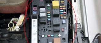
Block under the hood
This unit is located on the cover in front of the battery.
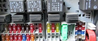
Decoding
p, blockquote 31,0,0,0,0 —>
| 1 | 60A Glow Plug Relay |
| 2 | 50A Cooling fan motor |
| 3 | 50A Cooling fan motor |
| 4 | 50A Anti-lock Braking System (ABS) |
| 5 | 110A/150A/175A generator |
| 6 | 30A Stability control system |
| 7 | 30A Anti-lock Braking System (with ESP) |
| 8 | 5A Stability control system |
Block arrangement
p, blockquote 6,0,0,0,0 —>
| 1 | Air conditioning control unit 1 - with automatic temperature control - in the heater control panel, front |
| 2 | Air conditioning control unit 2 - with automatic temperature control - in the heater control panel, rear - B-pillar |
| 3 | Evaporator Fan Control Module (Air Conditioning) - With Rear A/C - Behind Right Rear Trim Panel |
| 4 | Air conditioner/heater fan motor control unit 1 - with automatic temperature control - front - fan unit |
| 5 | Air conditioner/heater fan motor control unit 2 - with automatic temperature control - rear - underbody, center |
| 6 | Antenna signal booster - behind instrument panel, passenger side |
| 7 | Alternator resistor - near additional relays - CV/AUF, with alternator 150A / automatic transmission / automatic temperature control - behind the center of the dashboard |
| 8 | Additional battery - under the driver's seat |
| 9 | Accumulator battery |
| 10 | Central locking signal control unit - behind the dashboard |
| 11 | Cruise control control unit (with throttle motor) - cruise control functions are performed by the electronic engine control unit |
| 12 | Electronic cruise control module (without throttle motor) - behind the instrument panel, passenger side |
| 13 | Diagnostic Connector (DLC) - Instrument Panel, Driver's Side |
| 14 | Diagnostic unit - 05/99 (except AAC/ABL /AET/AES /AJA) - in the instrument cluster |
| 15 | Cooling Fan Motor Relay - Behind Left Headlight |
| 16 | Cooling fan motor resistor 1/2 - behind left headlight |
| 17 | Coolant heater control unit (with additional coolant heater - D3W/B4W/D4W) - in heater - underbody, center |
| 18 | Coolant Heater Control Module (with Auxiliary Coolant Heater - B7W/D7W) - Behind the Instrument Panel, Passenger's Side |
| 19 | Engine oil pressure warning buzzer - in the instrument cluster control unit |
| 21 | Fuse/Relay Box, Instrument Panel 1 |
| 22 | Fuse/Relay Box 2, Instrument Panel - Under Fuse/Relay Box 1, Instrument Panel |
| 23 | Instrument Panel Fuse/Relay Box 3 - Above Instrument Panel Fuse/Relay Box 1 |
| 24 | Fuse/Relay Box, Instrument Panel 4 - Behind the instrument panel, center |
| 25 | Fuse/Relay Box, Driver's Seat - Under Seat |
| 26 | Fuse/Relay Box, Engine Compartment - Battery Mounted |
| 27 | Additional fuse (5A/7.5A/10A) - in the rear of the audio system unit |
| 28 | Additional fuse (10A) - in the rear of the navigation system control unit |
| 29 | Warning buzzer for headlights not turned off - in the instrument cluster control unit |
| 30 | Heater Blower Motor Resistor - Manual Temperature Control - Fan Assembly, Front |
| 31 | Horn 1/2 - behind the front bumper |
| 32 | Immobilizer control unit - behind the instrument cluster |
| 33 | Immobilizer ring antenna - near the ignition switch |
| 34 | Turn signal relay, hazard warning relay - in hazard warning switch |
| 35 | Instrument cluster control unit/digital multifunction display - in instrument cluster |
| 36 | Outside air temperature sensor - behind the front bumper |
| 37 | Driver's seat heating control unit - in the seat heating switch |
| 38 | Passenger seat heating control unit - in the seat heating switch |
| 39 | SRS control unit - under the instrument panel, in the center |
| 40 | Electric sunroof control unit |
| 41 | Theme control unit - in the navigation system display |
| 42 | Telephone interface control unit - behind the instrument cluster |
| 43 | Electronic transmission control unit - near the engine control unit |
| 44 | Vehicle speed sensor - gearbox |
Replacing fuses in Volkswagen Transporter T5
Information about the purpose, as well as the fuse diagram for the Volkswagen Transporter T5 is located on the back of the block cover. There are also tweezers located there, with which you can replace the defective part.
On one's own
Let's look at the replacement procedure inside the car.
First, you need to use the T5 Conveyor fuse diagram to determine the location of the required insert. The work procedure is as follows:
- Remove the desired insert from the circuit board using tweezers and check it with a tester.
- If the part is burnt out, replace the insert with another one of the same rating. They are painted the same color, for example, a 10 A fuse is red.
- Close the lid and check the operation of the unit.
If the insert burns out again, it is necessary to repair this device. There is no point in changing the fuse again. You cannot install a part with a high rating; the system being tested may fail.
On service
- The cost of replacing a fuse at a service station is small, from 100-300 rubles. But a car enthusiast can carry out repairs on his own. The cost of inserts depends on the denomination and starts from 30-40 rubles.
- If you replace the fuse box for Volkswagen Transporter T5 circuits, you must contact a car service center. This will require tools and installation skills. This service will cost 1000 rubles. The price of the block is 5.4 thousand rubles.
To protect yourself from prolonged downtime on the road, the driver needs to have a set of the most common fuses in the glove compartment of the car. He must also clearly understand where to find a faulty fuse in the car and be able to replace it.
The video below will tell you about the locations of fuses on the Volkswagen T5:
The cigarette lighter fuse is discussed in this video:
Replacing a damaged fuse
To correctly replace a blown fuse T4, simply open the cover of the block, remove the fuse from its socket with special tweezers and install a new one in its place.
Safety elements of T4 on-board circuits are mainly located in the vehicle interior. The parts are easy to change and are quite reliable during active use of the car.
Specialization : Graduated from the State Automobile University, worked for 20 years at GAZ-56, now I drive a Zhiguli.
Source
Where is the Volkswagen T4 headlight relay located?
- RSS subscription
- Share Vkontakte
- Share on
Where are the fuses located in the Volkswagen Transporter? Volkswagen Transporter T5 car. The main power supply unit with fuses and relays in the car. The T 4 transporter is located in the vehicle interior.
(95) Headlight washer pump relay. 8. (99) Windshield wiper/washer intermittent relay. The fuse and relay box is located under the driver's seat. Decoding.
Location of Volkswagen T 4 components in the passenger compartment and engine compartment. Purpose. (36) Warning buzzer for headlights not turned off. (53) Fog lamp relay.
Five-pin connector under the steering wheel switch housing V Double-filament right headlight bulb L Single-pin connector at the rear of the T1h relay board.
Request to forum participants: Diagram of a device with a relay located behind the power supply on the dashboard Table of the purpose of the parts of the device with a relay Dismantling and replacement procedure Any car owner of Transporter minibuses will sooner or later be faced with the need to replace fuses.
Ukrainian Club – Forum of Shanuvalniks of German Buses Volkswagen Club • View topic – printout of fuse and relay box
I tried to find a diagram of the location and responsibility of the relay for T. The connecting contacts of the relay are standardized. When the consumer is turned on, the relay is controlled.
This means that by applying switching current to terminal 68, the switching circuit to terminal 85 is closed. The magnetic coil inside the relay draws in the core and closes the current circuit to the “Operating Current”.
The easiest way to check the functionality of the relay is to replace it with a new, working one.
This is what is done at the service station. Since an amateur does not always have the required relay at hand, the following working methods are recommended for handling the switching relay, which, among other things, are used to switch on headlights and fog lights. The terminal designations given here may differ, especially from serially installed relays.
Pull the relay out of the socket. Turn on the ignition and the corresponding switch. To do this, connect the indicator to ground -, carefully attach the second wire to terminal 30 in the relay socket. If the indicator diode lights up, there is voltage. Make a jumper from an insulated wire, exposing its ends. This technique does the same thing that a working relay would do if it were installed.
If, for example, the high beam lights up when the jumper is installed, then the relay is faulty. If the high beam does not light up, find out whether there is a ground connection to the headlight. Then, using the electrical circuit, find a break in the wire from terminal 87 to the headlight and repair it.
Volkswagen multivan fuses
- RSS subscription
- Share Vkontakte
- Share on
Where are the fuses located in the Volkswagen Transporter? Replacing Volkswagen Transporter T5 and T4 fuses yourself.
Technical club Volkswagen Transporter T4 T5 T6, we share our experience in repair and maintenance, a description of the fuses in the cabin under the cigarette lighter.
Volkswagen Transporter Long Busik › Logbook › Fuse diagrams for T5 GP. KM-Bender last online 6 days ago.
As mentioned above, the T5 minibus model is equipped with several electrical control devices. It’s as if I wrote a query in a search engine. Below is a diagram of the unit located in the vehicle interior in the central area of the console, as well as a table describing its components.
You can't get by with one page - there is a description of the elements - fuses, relays, actuators and electrical circuits sequentially not just for all models of Transporter, Caravel, Multivan, but also for all their possible versions of the “steepness” of the design, sliding door on the left, on the right, undershirts or firecrackers behind, etc.
Volkswagen Transporter | Fuses | Volkswagen Transporter
Driver's door electrical control unit. Left Rear Door Electrical Control Module with Power Sliding Door - Left Pillar. Passenger door electrical control unit.
Right rear door electrical control unit with power sliding door - right pillar "0".
The control unit for the ESP stability control system includes an acceleration sensor and a lateral movement sensor.
Control unit for the roof lifting mechanism and the van. Cooling fan motor control unit 2- in cooling fan motor 2- if installed.
Additional fuse 1 differential lock switch, rear 10A - left front pillar. Additional fuse 2 auxiliary heater 30A - under the left seat.
Additional fuse 3 door electrical control unit, left rear 40A - under the left seat on some models.
Resistor 1 of the heater fan motor - near the rear heater fan motor. Heater blower motor resistor 2 - near the rear heater blower motor - if equipped.
Volkswagen Transporter, VW T4, fuse diagram
Source: https://avtoevers.ru/speed23/predohraniteli-folksvagen-multivan.php
Emergency procedures for VW T5 Transporter. Replacing fuses VW T5 Transporter
7. Replacing fuses
Circuit breakers
Due to the fact that the car is constantly being improved and the purpose of fuses is constantly changing, it is impossible to provide a reliable specification of fuses in this section. The location of the fuses can be obtained from a Volkswagen Commercial Vehicles Dealership.
One fuse can protect the circuits of several electrical consumers. And vice versa: one consumer can have several fuses. Replace fuses only after eliminating the cause of their blown.
If the new fuse quickly blows again, have the relevant electrical equipment checked by a workshop.
WARNING The vehicle's electrical system contains high voltage and can cause electric shock, severe burns or death! Do not touch the ignition system wires under any circumstances.
Avoid short circuits in electrical equipment.
WARNING Using improper fuses, repaired blown fuses, or shorting unfused electrical circuits can cause fire and serious injury. Never install fuses with a higher current rating than required.
Replace blown fuses only with fuses of the same rating (color and markings must be identical) and size. Repaired fuses (so-called
"bugs") do not use!
It is prohibited to replace fuses with pieces of wire, paper clips and other improvised means!
Note To avoid damage to the electrical system in the car, before replacing the fuse, be sure to turn off the ignition, lighting (headlights, interior lighting, etc.) and all electrical devices and remove the key from the ignition switch.
Using high amperage fuses may cause damage elsewhere in the arterial circuit.
Protect exposed fuse boxes from dirt and moisture.
Dirt and moisture in the fuse box can cause damage to electrical equipment.
One electrical appliance may have several fuses. One fuse can protect the circuits of several electrical consumers.
Front panel fuses
Opening the fuse panel in the front panel (Multivan)
– Open the bottle holder in the front panel. – Squeeze both levers on the back of the bottle holder and remove the bottle holder.
– Insert a flat object, such as a screwdriver from an on-board tool, onto the top edge of the transparent cover and carefully lift the cover.
Opening the fuse panel in the front panel (Transporter)
– Press the recess under the drink holder and remove the lid towards the rear. Note The fuse box cover must be removed and installed correctly, being careful not to damage the vehicle.
Protect exposed fuse boxes from dirt and moisture. Dirt and moisture in the fuse box can cause damage to electrical equipment. There are other fuses in the vehicle that are not mentioned in this section. They can only be replaced at a service station.
Fuses in the engine compartment
Opening the fuse box in the engine compartment
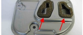
– Open the hood. – If necessary, remove the battery cover located on the rack. To do this, turn the quick release locks 90°. – Remove the partition (1) by moving it upwards. – Turn both quick release locks by 90°.
– Grasp the fuse box cover from the front and fold it up.
Closing the fuse panel in the engine compartment
– Close the fuse box cover and turn both quick release locks. – Insert the partition. At the same time, make sure that both recesses of the partition simultaneously cover the fuse cover jumper and the vertical partition jumper.
Replacing blown fuses