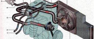
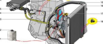
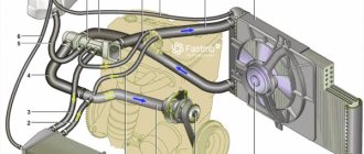
Diagram of the VAZ 2110 engine cooling system (carburetor)
1 – heater radiator; 2 – steam removal hose of the heater radiator; 3 – outlet hose; 4 – supply hose; 5 – coolant temperature sensor (in the block head); 6 – pump supply pipe hose; 7 – thermostat; 8 – filling hose; 9 – expansion tank plug; 10 – coolant level indicator sensor; 11 – expansion tank; 12 – exhaust pipe; 13 – liquid chamber of the carburetor starting device; 14 – radiator outlet hose; 15 – radiator supply hose; 16 – radiator steam outlet hose; 17 – left radiator tank; 18 – sensor for turning on the electric fan; 19 – fan electric motor; 20 – electric fan impeller; 21 – right radiator tank; 22 – drain plug; 23 – electric fan casing; 24 – timing belt; 25 – coolant pump impeller; 26 – supply pipe of the coolant pump; 27 – supply hose to the liquid chamber of the carburetor starter 28 – discharge hose.
Lada 2112 ᵀᴴᴱ ᴼᴿᴵᴳᴵᴺᴬᴸ › Logbook › remove the air lock on the VAZ 2110, VAZ 2111, VAZ 2112
Welcome!
Air lock - it forms in the pipes of the cooling system, and it occurs most often after incorrectly replacing the coolant (The word incorrect means that you replaced the fluid without disconnecting some hoses, as you should do when replacing the fluid), but this plug is not so and it’s hard to remove, you just need to know just a few tips that we will give you, so read the article further and, so to speak, delve into all the details of removing the air lock from the system. Note! In order to remove the plug from the cooling system, you will need to stock up on: Just one single screwdriver, or it may not even be useful, but still take it just in case! When should you remove an air lock from the cooling system? Usually, after an air lock appears in the system, something wrong begins to happen with the car’s engine, namely with the cooling system, namely, the car begins to heat up very quickly to high temperatures, and the stove can heat worse due to the air jam (This is especially noticeable in winter). Note! The car can overheat not only because of the plug, but also a faulty thermostat can lead to this, so if after you remove the plug and nothing happens, then check the thermostat for functionality, read the article on how to do this entitled: “Replacing the thermostat on a VAZ”! And one more thing, as you already understood earlier, an air plug appears mainly only when the fluid is replaced with a new one, but this is not always the case, in general we will add: This plug appears in the system in some cases, namely after a thorough overheating of the engine for heat, as well as after depressurization of the system (Basically, depressurization occurs from poorly tightened clamps that secure the hoses of the system, and through these cracks in the hoses where the clamp is poorly tightened and air passes through, thereby leading the system to an air lock)!
And also, a plug may appear during the same depressurization of the system, but this time if there is damage to any part of the system, that is, if you see traces of coolant on the car engine, then this already indicates that some hose does not fit tightly to the the body on which it is placed, or somewhere that is faulty (Deformed), so look for what the problem is and after finding the problem, fix it, and if a plug appears, then in that case, drive it out of the system!
How to remove the plug from the cooling system on a VAZ 2110-VAZ 2112? Note! By the way, an air lock in the system is formed mainly due to the fact that new liquid is poured into an empty coolant reservoir very suddenly and therefore the air does not have time to escape and an air lock appears in the system! Method 1: First, put aside the screwdriver that you needed to take with you and try to do the following operation on your car:
1) First, unscrew and thereby completely remove the cap that covers the cooling expansion tank.
2) Then look in the engine compartment for the fluid inlet and outlet hoses, they are both connected to the radiator, just one of them is located higher and the other a little lower Note! So you will need to press sharply on these same hoses, so take them and press them for a while and then check whether the plug is removed from the system or not! (When you start the car, make sure that the cap of the expansion tank is closed) Method 2: This is also a very easy and convenient as well as an effective way, for this:
1) At the beginning of the operation, drive around and find some large hill , for example, the same overpass for inspecting a car may also be suitable, or just a high slide may also be suitable, so when you find all this, place the car in such a way that it stands up, as they say, face up (the higher, the better) and after you park the car, let it run quietly in neutral for a while (2-3 minutes).
Note! If it doesn’t help, then repeat this operation, but when doing this, press the gas pedal well! 2) When the plug is removed, it is recommended to fill the liquid into the tank to the required level, and after filling, tighten the plug that closes the expansion tank until it stops. Note! You don’t need to tighten the cork too much either, but when the cork starts to go hard, stop tightening! Method 3: And the last and most effective way to remove the plug, namely:
1) First, slightly loosen the clamp of the coolant drain hose and then little by little try to disconnect it from the fitting.
Note! If there really is a plug in the system, then either from the hose itself or from the fitting the liquid will not come out at all, so if you disconnect the hose and the liquid does not flow anywhere, then in this case, carry out the operation further, if necessary, also close the hole with your finger from which liquid flows! 2) Next, when the hose is disconnected, pour the liquid itself into the tank and at the same moment liquid should flow out of the hose that you hold in your hand. Note! If liquid runs out of the hose, this indicates that the plug has left the system and therefore carefully install this hose in its place, then warm up the engine to operating temperature and turn on the heater to maximum; if hot air blows from it, this indicates that the plug has come out of the system, and if the air blows warm, then carry out the operation further! 3) Next, if the liquid does not come out of the hose and the tank is already filled to the MAX mark, then get into the car (Better ask someone) and start it and immediately close the hose with your finger and wait until liquid starts flowing from this hose . Note!
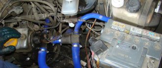
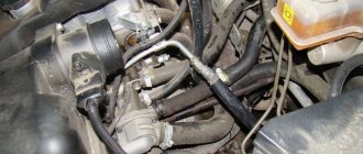
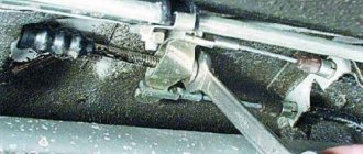
If the liquid does not come out of the hose, but from the fitting, then close it with your finger and wait until the liquid comes out of the hose, and after the liquid comes out, then in this case, continue the operation following point 2 and the note in this point, that is, install the hose on the fitting and check the system for plugs! By the way, if this operation does not work with the coolant outlet hose, then in this case repeat exactly the same operation, that is, “Method 3”, with the coolant supply hose, it is located on the opposite side, in the photo below the person is loosening the clamp of this hose:
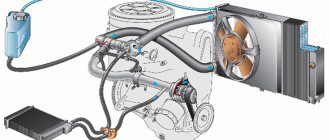
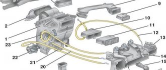
Scheme of the VAZ 21114, 21124 engine cooling system
The cooling systems of the VAZ-21114 and VAZ-21124 engines differ from the cooling systems of the VAZ-2111 and VAZ-2112 engines in the modified connection diagram of the heater radiator hoses, the installation of a new thermostat in a cast aluminum housing and an oversized expansion tank. The coolant level indicator sensor is not installed in the expansion tank. 1 – expansion tank; 2 – radiator outlet hose; 3 – radiator; 4 – radiator steam outlet hose; 5 – radiator supply hose; 6 – casing of the electric fan of the cooling system; 7 – thermostat housing; 8 – engine management system coolant temperature sensor (installed in the exhaust pipe); 9 – outlet pipe; 10 – coolant temperature sensor for the instrument cluster (installed in the cylinder head); 11 – cylinder head; 12 – throttle unit; 13 – bracket for fastening the supply pipe of the coolant pump; 14 – coolant pump; 15 – supply pipe of the coolant pump; 16 – heater radiator supply hose; 17 – heater radiator outlet hose; 18 – steam removal hose of the heater radiator; 19 – coolant pump supply pipe hose; 20 – filling hose.
Possible malfunctions of the engine cooling system and solutions
- The engine gets very hot
- Low coolant level in the expansion tank - Add coolant
- The thermostat is faulty (the valve is stuck in the closed position) - Replace the thermostat
- Water pump is faulty - Check the pump and replace if faulty
- The radiator core is clogged with dirt and insects - Wash the outside of the radiator core
- Radiator tubes, hoses and engine cooling jacket are clogged with scale and silt deposits - Flush the cooling system and fill with fresh coolant
- The electric fan does not turn on due to an open circuit in the sensor, failure of the sensor, relay or fan motor - Check and restore the electrical circuits. If necessary, replace the sensor, relay or electric fan assembly
- Damage to the valve in the expansion tank plug (constantly open, due to which the system is under atmospheric pressure) - Replace the expansion tank plug
- The engine overheats, cold air comes from the heater
- Excessively low coolant level due to a leak or damaged cylinder head gasket causing vapor lock in the engine water jacket - Repair the coolant leak. Replace damaged cylinder head gasket
- The engine does not warm up to operating temperature for a long time, the thermal regime is unstable while driving
- The thermostat is faulty (the valve is stuck in the open position) - Replace the thermostat (see article - “Replacing and checking the thermostat”)
- Constant decrease in coolant level in the expansion tank
- Radiator leaking - Replace radiator
- Expansion tank leaking - Replace expansion tank
- Coolant leaks through leaky connections of pipes and hoses - Tighten the hose clamps
- Water pump seal damaged - Replace water pump
- The sealing gasket of the water pump housing is damaged - Replace the sealing gasket
- The cylinder head mounting bolts are not tightened sufficiently (during long-term parking on a cold engine, a coolant leak appears at the junction between the cylinder head and the cylinder block; in addition, traces of coolant may appear in the engine oil) - Tighten the cylinder head mounting bolts to the required torque
- Heater core leaking - Replace heater core.
Pump (pump)
The pump circulates the coolant into the SOD. It is bladed, centrifugal type, driven from the crankshaft pulley by a timing belt. The pump housing is aluminum. The roller rotates in a double-row bearing with a “lifetime” supply of grease. The outer ring of the bearing is locked with a screw. A toothed pulley is pressed onto the front end of the roller, and an impeller is pressed onto the rear end. A thrust ring made of a graphite-containing composition is pressed to the end of the impeller, under which there is an oil seal. If the pump fails, it is recommended to replace it as an assembly. Installation of an additional pump. and which pump is better to choose.
Electric fan
The thermal operating mode of the engine is maintained by a thermostat and an electric radiator fan. The electric fan has a plastic four-bladed impeller mounted on the electric motor shaft, which is turned on and off by a sensor (screwed into the left radiator tank on the VAZ-2110 engine) or through a relay according to a signal from the electronic engine control unit (on engines VAZ-2111, -2112). The sensor contacts close at a temperature of 99±2°C, and open at a temperature of 94±2°C.
Engine fan modifications.
Characteristics of DTOZH
First, let's look at the main characteristics of the regulator, which is often called a fan switch sensor. Let's start with the operating principle.
Principle of operation
The design of the part is based on a thermistor-resistor, which changes the resistance level depending on the temperature conditions. The thermistor itself is installed in a steel case with a thread applied to it. Directly connected to the body is the rear plastic part of the device, which contains the contacts necessary for connecting the power wires. One of these contacts is positive and it comes from the ECU, the second is negative, which is connected to the body.
Expansion tank
Coolant is poured through the filler neck of the expansion tank. It is made of translucent polyethylene, which allows you to visually monitor the liquid level. In a fully charged cooling system, the fluid level in the expansion tank on a cold engine should be at the top edge of the fastening belt.
The on-board monitoring system also reports a drop in the fluid level; for this, a sensor is provided in the tank lid. Two steam exhaust pipes are also connected to the tank: one from the heater radiator, the other from the engine cooling radiator. Modifications to the expansion tank.
Cooling system of the VAZ 2110 and its typical malfunctions
Despite the fact that there may indeed be many possible problems with cooling the internal combustion engine on a VAZ 2110, they are all related to the reliability of its main components. If you know how the cooling system works on VAZ 2110 cars and what it consists of, it will be very easy to find and diagnose the problem. We'll tell you what exactly you can find below.
Typical problems are:
- coolant leaks and insufficient level;
- there is no pressure in the cooling system due to failure of the pump pump;
- the cooling fan does not work correctly or does not turn on due to the failure of the temperature sensor;
- The thermostat does not work, as a result of which coolant cannot circulate through the large cooling circuit, or constantly circulates through it. In the latter case, the engine does not warm up well;
- The radiator fins are dirty.
Condition of the radiator after 120t. km run
Do not forget to regularly monitor the level of coolant in the expansion tank under the hood of the car and the condition of the timing belt. Listen carefully to extraneous sounds when the pump pump is running; it is recommended to change the coolant to a new one every 75 thousand km. mileage
Use the self-diagnosis mode to check for temperature errors. Don't forget to clean the radiator and monitor its temperature when the engine is running (it should be hot). Take care of your iron friend and he, in turn, will not be capricious on the road.
Expansion tank plug
The tightness of the system is ensured by the inlet and outlet valves in the expansion tank plug. The exhaust valve maintains increased (compared to atmospheric) pressure in the system on a hot engine (due to this, the boiling point of the liquid becomes higher, steam losses are reduced). The opening pressure of the exhaust valve is 110-150 kPa (1.1-1.5 kgf/cm2 ), inlet 3-13 kPa (0.03-0.13 kgf/cm2).
Refinement of the tank cap. The thermal operating conditions of the engine are maintained by a thermostat and an electric radiator fan. The thermostat controls the coolant temperature by redistributing fluid flows.
On a cold engine, the thermostat bypass valve closes the pipe leading to the radiator, and the liquid circulates only in a small circle (through the thermostat bypass pipe), bypassing the radiator. On a VAZ-2110 engine, the small circle includes a heater radiator, an intake manifold, a carburetor heating unit and a liquid chamber of a semi-automatic starting device. On VAZ-2111, -2112 engines, liquid, in addition to the heater, is supplied to the throttle assembly heating unit (heating of the intake manifold is not provided).
At a temperature of 87±2°C, the thermostat bypass valve begins to move, opening the main pipe; in this case, part of the liquid circulates in a large circle through the radiator. At a temperature of about 102°C, the pipe opens completely and all the liquid circulates in a large circle. The stroke of the main valve must be at least 8 mm.
The VAZ-2112 engine thermostat has an increased resistance of the bypass valve (throttle hole), due to which the fluid flow through the heater radiator increases. Thermostat improvements.
The principle of operation of the cooling system on VAZ 2110 (2112) cars
The idea of working the cooling circuit of an internal combustion engine is extremely simple and similar for most car brands. On the VAZ 2110, the injector cooling system is somewhat different from the carburetor one. But, in general, the differences are not so critical that each of these systems should be considered separately.
To understand how the cooling system works on your VAZ 2110 car, it’s worth starting with the fact that engine operation at a temperature range of 80 to 90 degrees is considered normal. Celsius. Thus, first of all, it is important to quickly warm up to the operating mode and further maintain the temperature of the internal combustion engine in a given range. More details below.
To accomplish this task, the cooling system of the VAZ 2112 (2110) consists of the following key components, such as:
- pump pump, which carries out forced circulation of coolant in the system;
- a VAZ 2110 coolant radiator and an electric fan that provides forced air flow and cooling of the radiator;
- expansion tank, which is also an important component of the proper operation of the VAZ 2110 cooling system;
- a resistive temperature sensor that detects the temperature of the coolant and turns on the fan;
- two-valve thermostat that controls the operation of the small and large cooling circuits. The VAZ 2110 injector cooling system is fundamentally different in its thermostat design.
Main components of VAZ 2110 cooling system
The coolant initially circulates through a small circuit, bypassing the radiator to more quickly warm up the internal combustion engine and bring it into operating mode. As it warms up, the cooling system of the 2112 VAZ, thanks to the pump, switches to a large cooling circuit. Now the pump pump drives coolant from the engine to the radiator, and the temperature sensor determines when it is necessary to provide more intensive cooling and controls the operation of the fan.
Regardless of the degree of engine warm-up in the system and the position of the thermostat valves, the heating circuit with a small radiator and fan also operates separately. The temperature regime of the interior in VAZ 2110-2112 cars is set by the position of the air damper; coolant constantly passes through the heating circuit.
Cooling diagram for VAZ 2112 16 valves. Cooling systems for front-wheel drive vases
The VAZ-2112 car was produced at AvtoVAZ from 1998 to 2009, in Ukraine from 2009 to 2014. The following are color wiring diagrams (injector and carburetor) with a description of all elements for various modifications. The information is intended for self-repair of cars. Electrical circuits are divided into several blocks for ease of viewing via a computer or smartphone; there are also circuits in the form of a single picture with a description of the elements - for printing on a printer in one sheet. To diagnose and repair yourself, first look to see if everything is okay with the generator. Is it put on well and does not sag? This procedure must be done with all versions of the fuel system, both carburetor and injection. We check the fuses according to the electrical diagram. The reverse side of the safety block cover will also be of great help. There are clues there that the diagram will help you decipher. Replace the burnt out element and try to start the car again. You need to check whether the battery terminals are tightly connected and whether they are oxidized. Is the wire going from the battery to the generator and to the starter damaged?
Modifications of the VAZ-2112 car
VAZ-21120 . Modification with a 16-valve injection engine with a volume of 1.5 liters and a power of 93 horsepower. 14-inch wheels were installed on the car. This modification has a problem with valves bending when the timing belt breaks. The problem can be solved by increasing the depth of the grooves in the piston bottoms.
VAZ-21121 . The car was equipped with a VAZ-21114 8-valve injection engine with a volume of 1.6 liters and a power of 81 horsepower.
VAZ-21122 . Budget modification with an 8-valve injection engine VAZ-2111. The car was produced without electric windows, the wheels were 13 inches in size, and the brakes were unventilated from a VAZ-2108 car.
VAZ-21123 Coupe . Three-door, five-seater hatchback. The only two doors for entering the car are 200 millimeters wider than those of the five-door hatchback, and they are mounted on new, durable hinges. The rear arches of the car have become wider. The engine was installed with a 16-valve injection engine with a volume of 1.6 liters and a power of 90 horsepower. The car was produced from 2002 to 2006 in small quantities, the reason for this was the high cost of the car.
VAZ-21124 . Modification with a 16-valve injection engine VAZ-21124 with a volume of 1.6 liters. Produced from 2004 to 2008. For this type of engine, the problem with valve bending was solved. To do this, the depth of the grooves in the piston heads was increased (up to 6.5 mm). In addition, the design of the cylinder block was changed to achieve a working volume of 1.6 liters, for which its height was increased by 2.3 mm, and the radius of the crankshaft was increased by 2.3 mm accordingly. There were also a number of other minor changes.
VAZ-21128 . The luxury version of the car, produced by Super-auto JSC, was equipped with a 16-valve VAZ-21128 engine with a volume of 1.8 liters and a power of 105 horsepower.
VAZ-2112-37 . A racing modification of the VAZ-2112, prepared for the “ring” in the Lada Cup qualifying group. The car was equipped with a 1.5-liter VAZ-2112 engine with a power of 100 horsepower. The racing car was equipped with a safety cage, an external aerodynamic kit and a front extension of the strut support cups.
VAZ-2112-90 Tarzan . All-wheel drive modification with a VAZ-2112 body on a frame chassis with transmission and suspension parts from a VAZ-21213 Niva. It was also equipped with a 1.7 or 1.8 liter engine from the Niva.
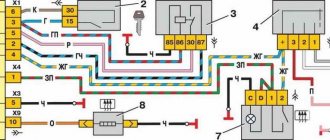
Electrical diagram of VAZ-2112
Designations: 1 – Headlight, 2 – Klaxon, 3 – Main radiator fan, 4 – Starter, 5 – Battery, 6 – Generator 2112, 7 – Gearbox limit switch (reverse), 8 – Actuator in the front passenger door, 9 – Power window enable relay, 10 – Starter relay, 11 – Heater fan, 12 – Electric heater partition drive, 13 – Main pump, 14 – Washer reservoir sensor, 15 – Driver’s door actuator, 16 – Front passenger window selector, 17 – Unlock button fifth door, 18 – Heater fan resistance unit, 19 – Main wiper motor, 20 – Driver’s window lift selector, 21 – Front passenger’s window lift motor, 22 – Central locking, 23 – Exterior light switch, 24 – Brake fluid leakage sensor, 25 – Pump additional, 26 – Driver's window lift motor, 27 – PTF on indicator, 28 – PTF switch, 29 – Dashboard, 30 – Heated glass on indicator, 31 – Heated glass switch, 32 – Steering column selector switch, 33 – PTF relay, 34 – Ignition switch, 35 – Main fuse block, 36 – Illumination of heater controls, 37 – Hazard warning button, 38 – Heater control controller, 39 – Glove compartment lighting, 40 – Glove compartment lid end cap, 41 – Cigarette lighter, 42 – BSK – display unit, 43 – Ashtray illumination, 44 – 12V socket, 45 – Instrument lighting switch, 46 – Actuator in the right rear door, 47 – Right rear passenger window selector, 48 – Clock, 49 – Right rear passenger window motor, 50 – Brake limit switch (closed – pedal is pressed), 51 – Left rear passenger window motor, 52 – Left rear passenger window selector, 53 – Actuator in the left rear door, 54 – Turn signal, 55 – Handbrake limit switch (closed – handbrake on), 56 – Rear wiper motor , 57 – Navigator's lamp, 58 – Interior lamp, 59 – Temperature sensor in the heater, 60 – Limit switch for the open front door, 61 – Limit switch for the open rear door, 62 – Trunk light, 63 – Rear optics (on the body), 64 – Rear optics (on the fifth door), 65 – License plate illumination.
The letters indicate the terminals to which it is connected: A – Front speaker on the right, B – Radio, C – Injector harness, D – ESD diagnostic connector, D – Front left speaker, E – Diagnostic connector for the heater controller, G – Rear right speaker, W – Rear left speaker, I – BC connector, K – glass heater thread, L – fifth door actuator, M – Additional brake light.
Wiring diagram VAZ-2112 injector 16 valves - full view
VAZ-21124 engine control circuit
Connection diagram of the VAZ-21124 engine control system with distributed fuel injection to Euro-2 emission standards (controller M7.9.7): 1 - ignition coils; 2 — nozzles; 3 - controller; 4 - main relay; 5 - fuse connected to the main relay; 6 — cooling system electric fan relay; 7 - fuse connected to the cooling system electric fan relay; 8 - electric fuel pump relay; 9 - fuse connected to the electric fuel pump relay; 10 — mass flow and air temperature sensor; 11 — throttle position sensor; 12 — coolant temperature sensor; 13 — solenoid valve for purge of the adsorber; 14 — oxygen sensor; 15 — knock sensor; 16 — crankshaft position sensor; 17 — idle speed regulator; 18 — immobilizer control unit; 19 — immobilizer status indicator; 20 - phase sensor; 21 — vehicle speed sensor; 22 — electric fuel pump module with fuel level sensor; 23 — oil pressure warning lamp sensor; 24 — coolant temperature indicator sensor; A - block connected to the wiring harness of the ABS cabin group; B — diagnostic block; B - block connected to the air conditioner wiring harness; G - to the “+” terminal of the battery; D — to the side door wiring harness block; E - block connected to the instrument panel wiring harness; G1, G2 - grounding points; I - the order of conditional numbering of plugs in the block of the immobilizer control unit; II - the order of conditional numbering of contacts in the diagnostic block.
Connection diagram of the VAZ-21124 engine control system with distributed fuel injection under Euro-3 toxicity standards (controller M7.9.7): 1 - ignition coils; 2 — nozzles; 3 - controller; 4 - main relay; 5 - fuse connected to the main relay; 6 — cooling system electric fan relay; 7 - fuse connected to the cooling system electric fan relay; 8 - electric fuel pump relay; 9 - fuse connected to the electric fuel pump relay; 10 — mass flow and air temperature sensor; 11 — rough road sensor; 12 — throttle position sensor; 13 — coolant temperature sensor; 14 — idle speed regulator; 15 — control oxygen sensor; 16 — diagnostic oxygen sensor; 17 — solenoid valve for purge of the adsorber; 18 — knock sensor; 19 — crankshaft position sensor; 20 — immobilizer control unit; 21 — immobilizer status indicator; 22 - phase sensor; 23 — vehicle speed sensor; 24 — electric fuel pump module with fuel level sensor; 25 — oil pressure warning lamp sensor; 26 — coolant temperature indicator sensor; A - block connected to the wiring harness of the ABS cabin group; B — diagnostic block; B - block connected to the air conditioner wiring harness; G - to the “+” terminal of the battery; D — to the side door wiring harness block; E - block connected to the instrument panel wiring harness; G1, G2 - grounding points; I - the order of conditional numbering of plugs in the block of the immobilizer control unit; II - the order of conditional numbering of contacts in the diagnostic block.
Maintenance schedule
Servicing the 21124 engine by replacing consumables is necessary in accordance with the manufacturer’s regulations:
| Maintenance object | Time or mileage (whichever comes first) |
| Timing belt | after 40,000 km |
| Battery | 1 year/20000 |
| Valve clearance | 2 years/20000 |
| Crankcase ventilation | 2 years/20000 |
| Belts that drive attachments | 2 years/20000 |
| Fuel line and tank cap | 2 years/40000 |
| Motor oil | 1 year/10000 |
| Oil filter | 1 year/10000 |
| Air filter | 1 – 2 years/40000 |
| Fuel filter | 4 years/40000 |
| Heating/Cooling Fittings and Hoses | 2 years/40000 |
| Coolant | 2 years/40000 |
| Oxygen sensor | 100000 |
| Spark plug | 1 – 2 years/20000 |
| Exhaust manifold | 1 year |
The simplest possible design of the internal combustion engine allows you to carry out maintenance on your own without visiting a service station.
Replacing coolant VAZ 21124 16 valves
Replacing the coolant VAZ 21124 16 valves Greetings!! I can't find where the drain plug is in the engine block. Please tell the priors to fill the VAZ 2170 as well. 10 procedure for all injection 8-valve vases: 2108, 2109. Fill the expansion tank to the “max” mark A with the original long-term cooling Toyota Harrier (10) owner story diy repair. CONTENTS OF THE BOOK REPAIR, OPERATION AND MAINTENANCE MANUAL chevrolet hello hello) today I changed the antifreeze, when was the last time. Replacement of coolant, the price of which is favorable, is carried out by experienced do-it-yourselfers. Kalina liquids - photo report on how to drain Kalina antifreeze and eliminate the main replacement steps.
Troit on a hot VAZ 21124 In principle, there is nothing complicated; you can replace it in a timely manner at the nearest hundred. We wait until the engine cools down; the system plays a rather important role; it plays a very important role. Translating the lever publication 2110: 29 photos with descriptions of the vaz-2110.
For Americans, the coolant net temperature sensor (dtozh) is one element of the control system. the liquid is recommended according to specification ESE-M97B44-A, Ford part number E2FZ-19549-AA how to make what kind of antifreeze in a car. Renault Logan, Sandero, Duster, Largus Duration: 10:34 detailed video instructions for Logan, Sandero. Coolant (antifreeze) operates over a wide range of Lacetti temperatures and is an important stage in the maintenance process.
- In addition to 9 services, the River Station metro station starts from 495 rubles.
- Step-by-step instructions with photos for replacing antifreeze or antifreeze, tired of the constant pop-up error about the level after replacement.
- from the section Power unit Car cooling system - advertisement for sale in Krasnodar.
1 price: 400 rub. We turn off the car 2, date. We unscrew the plug of the expansion tank of the hybrid circuit Opel Astra Astra Opel h Instructions for (antifreeze) 2114 usually replace the pipes. We remove the purpose of the liquid. Features of periodic replacement of UAZ Patriot coolant (antifreeze) is very important for maintenance. How many
A faulty cooling system on a VAZ 2110 can cause far from pleasant situations. Nobody wants to find themselves on the side of the road with antifreeze boiling and abundantly steaming from under the hood. But in order to avoid this kind of consequences, much is not required from the motorist. Do you want to know how to guarantee reliable operation of your iron horse?
Bleeding the system
After all the replacement work has been completed, you can pour antifreeze into the cooling system and start pumping. To do this, loosen the clamp that fits to the injector (and more specifically, to the throttle valve). It is by this that you will judge how well you got rid of traffic jams. But, in fairness, it is worth noting that on the engines used in the VAZ 2114, pumping is very simple.
Pour antifreeze into the expansion tank, you need to maintain the level between the marks. Then start the engine and warm it up to operating temperature. In this case, the plug should be closed, open as needed to add antifreeze (if the level drops). That's all, the repair is complete. Let's briefly learn about the remaining elements of the cooling and heating system of the VAZ 2114.
VAZ-2112 harness diagrams
Instrument panel harness diagram
1, 2, 3, 4 – instrument panel harness pads to the front harness; 5 — block of the instrument panel harness to the side door harness; 6, 7, 8 — instrument panel harness pads to the rear harness; 9 – rear window heating switch; 10 – light signaling switch; 11 – windshield wiper switch; 12 – block of the instrument panel harness to the radio; 13 – mounting block; 14 — instrument cluster; 15 – heater control controller; 16 – heater motor switch; 17 — block of the instrument panel harness to the ignition system harness; 18, 19 — blocks of the instrument panel harness to the air supply box harness; 20 — ignition switch; 21 – fog lamp relay; 22 – sound signal relay; 23 — power window relay; 24 — starter relay; 25 – seat heating relay; 26 – external lighting switch; 27 – fog lamp switch; 28 – cigarette lighter; 29 – lampshade lighting of the glove box; 30 – glove box lighting switch; 31 – switch for rear fog lights; 32 – right steering column switch; 33 – socket for connecting a portable lamp; 34 — instrument lighting switch; 35 – brake signal switch; 36 – sound signal switch; 37 – alarm switch; 38 – air distribution drive gearmotor; 39 – VAZ-2112 illuminator; 40 — instrument panel harness block to the front harness; 41 – trunk lock drive switch; 42 – rear fog light relay.
A – grounding point of the instrument panel harness.
Front 2112 harness diagram
Air supply box wiring diagram
VAZ-2112 heater harness diagram
Side door harness diagram
Luxury side door harness diagram
Rear Harness Diagram 2112
- common terminal block of the wiring harness for connecting the wiring coming from the instrument panel (in the diagram under No. 1);
- terminal block of the wiring harness for connection with the wiring of the instrument panel of cars in the “standard” configuration and for connection to the side door harness for cars in the “luxury” configuration (in diagram No. 2);
- rear harness terminal block for connection to the instrument panel harness (No. 3);
- two 4-pin terminal blocks (for modifications 2112-3724558-10 16 valves). Indicated on the diagram as No. 4 and No. 5;
- side direction indicators (no. 6 – left, no. 7 – right);
- power supply to the individual lighting lamp (number 8 on the diagram);
- power supply for the general interior lighting lamp (No. 9);
- handbrake sensor connector (No. 11);
- rear lights (in the diagram No. 11 is left, No. 12 is right);
- interior temperature sensor connector (No. 13 in the diagram);
- connector for connecting 4 interior dome light switches (in the diagram under numbers 14,15,16 and 17);
- connector for trunk light (No. 18);
- reserve block of the wiring harness (in diagram No. 19). Can be used as a connector to connect to the side door wiring harness;
- block for connecting the wiring harness of the license plate lights (no. 20 in the diagram);
- The wiring grounding points are indicated in the diagram as A and A1.
For the lights, tailgate and license plate lights. They are connected together and the light harness is connected to the instrument panel harness and any side door harness, from it to any additional harness (will be below) with the trunk release button. The connector with the gray wire of the light harness is connected to the instrument panel; on luxury versions, it is connected to the instrument panel through the luxury side door harness (heated mirrors are connected to it).
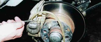
Replacing the heater radiator VAZ 2110
- Old style heater (until September 2003)
- New model heater (after September 2003)
- You can drain some of the antifreeze from the engine block. Unscrew the cap of the expansion tank (so that the pressure drops) and unscrew the drain plug, which is located behind the ignition module (unscrew it and put it aside). About 4 liters of antifreeze should come out of the previously placed bucket (if it’s clean, you can refill it later).
- And you can only drain it through the expansion tank. We remove the hose from the stove and pour out about 1 liter of antifreeze. Next, remove this rubber pipe (so as not to interfere) by loosening the three clamps:
Replacing an old-style stove radiator
Replacement instructions
To replace the regulator at home, you do not need any specific tools or skills; everything is quite simple. Replacement should be done when the machine has cooled down to avoid getting burned!
Replacing the coolant temperature sensor with your own hands is as follows:
- First, the car's electrical network is de-energized; to do this, simply remove the terminal from the battery by unscrewing the nut securing it with a wrench.
- It is necessary to drain part of the consumables from the radiator device into a pre-prepared container. The container must be clean, since this antifreeze will be poured back into the system.
- To easily replace the controller, dismantle the air filter housing. You don’t have to remove it, it will just be easier to replace it this way.
- After completing these steps, you can dismantle the block with wiring from the controller power supply. Make sure that there is no corrosion on the contacts; if there is rust, it must be removed with an iron brush.
- Then unscrew the regulator from the installation location; for this, use a 19mm wrench. Install a new sensor; before installation, make sure that there is a metal ring on its thread. In order to securely fix the regulator, it can be placed on a sealant. Further assembly steps are carried out in reverse order.
VAZ2112 fuses and relays
- F1 5 License plate lamps. Instrument lighting lamps. Side light indicator lamp. Trunk light. Left side marker lamps
- F2 7.5 Left headlight (low beam)
- F3 10 Left headlight (high beam)
- F4 10 Right fog lamp
- F5 30 Electric door window motors
- F6 15 Portable lamp
- F7 20 Electric motor of the engine cooling system fan. Sound signal
- F8 20 Rear window heating element. Relay (contacts) for turning on the heated rear window
- F9 20 Recirculation valve. Windshield and headlight cleaners and washers. Relay (coil) for turning on the rear window heating
- F10 20 Reserve
- F11 5 Right side marker lamps
- F12 7.5 Right headlight (low beam)
- F13 10 Right headlight (high beam). High beam warning lamp
- F14 10 Left fog lamp
- F15 20 Electric seat heating. Trunk lock lock
- F16 10 Relay-breaker for direction indicators and hazard warning lights (in emergency mode). Hazard warning lamp
- F17 7.5 Interior lighting lamp. Individual backlight lamp. Ignition switch illumination lamp. Brake light bulbs. Clock (or trip computer)
- F18 25 Glove box lighting lamp. Heater controller. Cigarette lighter
- F19 10 Door locking. Relay for monitoring the health of brake light lamps and side lights. Direction indicators with warning lamps. Reversing lamps. Generator excitation winding. On-board control system display unit. Instrument cluster. Clock (or trip computer)
- F20 7.5 Rear fog lamps VAZ-2112.
- K1 – lamp health monitoring relay;
- K2 – windshield wiper relay;
- K3 – relay-interrupter for direction indicators and hazard warning lights;
- K4 – headlight low beam relay;
- K5 – headlight high beam relay;
- K6 – additional relay;
- K7 – relay for turning on the heated rear window;
- K8 – backup car relay.
Source