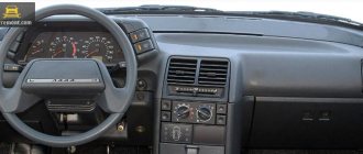
VAZ dashboard pinout
When repairing or replacing the dashboard (instrument panel) of VAZ cars with a more convenient and modern version of VDO, made with LEDs, you will need connection diagrams and pinouts of panel connectors. For this purpose, the editors of 2SHEMI.RU have prepared a complete collection of panel contact pinouts for all popular models of this car.
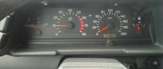
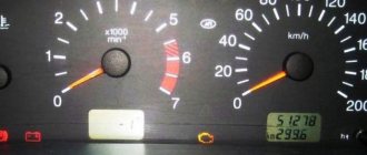
The main symbols that are found on the dashboard of absolutely any car of the VAZ family are: speedometer, fuel gauge, tachometer and sensors to indicate engine temperature.
Characteristics
- Post office. Delivery to your locality depends on the distance from Tolyatti. On average 5-14 days in Russia. Delivery cost from 200 rub.
— Russian Post 1st class. Delivery to your locality depends on the distance from Tolyatti. On average 2-6 days in Russia. Cost from 250 rub. and the weight of the parcel is no more than 2 kg.
- Transport companies . We cooperate with many transport companies. During our work, we found out which companies carry out their activities efficiently and inexpensively. Transport companies deliver within 1-10 days across Russia and 5-14 days to Kazakhstan.
— TK PEK (pecom.ru) — One of the large transport companies. Many branches throughout Russia. Delivery from 300 rub.
— TK Ratek (rateksib.ru) — Shipments throughout Russia and Kazakhstan
— TC Business Lines (dellin.ru) — you must send your passport details
— GTD (Former KIT)
— Dispatch across Russia and Kazakhstan.
— Pickup . You yourself come and pick up the goods from our office/warehouse. Only by prior appointment.
Notification: Upon dispatch, we will notify you and send you an invoice number (identifier) by which you can track your cargo. Upon arrival at the transport company's branch warehouse, managers will notify you about the arrival of the cargo, the delivery amount and the address by phone and/or SMS.
Russian Post. An arrival notification will be sent to your email address.
Expert opinion
It-Technology, Electrical power and electronics specialist
Ask questions to the “Specialist for modernization of energy generation systems”
Description of the dashboard How the mass of the ECU works, how to check the mass of the ECU, what problems may arise and how to modify it to avoid troubles in the future. Ask, I'm in touch!
Pinout of the dashboard of VAZ2105, 2106, 2107
Old panel (with oil pressure gauge)
In addition to the presence of an oil pressure indicator, it is worth noting that this instrument panel does not have an air damper indicator lamp (choke), and the emergency oil pressure lamp is located next to the pressure indicator. Because of this, it contains lamps for low brake fluid levels and fog lamps.
White 6-terminal block X1:
- Gasoline level sensor
- Turn signal indicator lamp
- Battery charge sensor (voltmeter -)
- Gasoline level warning lamp
- Overall plus (+)
- Battery charge sensor (voltmeter +)
White 8 terminal block X2:
- Fog lamp warning lamp
- High beam warning lamp
- Dimensions indicator lamp
- Empty
- Battery charge indicator lamp
- Brake fluid level warning lamp
- Empty
- Parking brake warning lamp
Orange 6-terminal block X3:
- General minus (-)
- Tachometer VAZ
- Instrument lighting
- Oil pressure sensor
- Oil pressure warning lamp
- Coolant temperature sensor
New instrument panel (with econometer)
Here, everything is the other way around - there is no oil pressure indicator (instead there is an econometer), instead of a brake fluid level lamp there is a suction lamp (or an engine management system lamp on injectors), and instead of a fog lamp lamp there is an oil pressure lamp.
White 6-terminal block X1:
- Gasoline level sensor
- Turn signal indicator lamp
- Battery charge sensor (voltmeter -)
- Gasoline level warning lamp
- Overall plus (+)
- Battery charge sensor (voltmeter +)
White 8 terminal block X2:
- Dimensions indicator lamp
- High beam warning lamp
- Oil pressure warning lamp
- Empty, but there is a terminal in the wiring that goes to the brake fluid level sensor
- Battery charge indicator lamp
- Indicator lamp for the air damper (choke) or engine control unit for injectors
- Empty
- Parking brake warning lamp (handbrake)
Orange 6-terminal block X3:
- General minus (-)
- Tachometer (if this contact is empty, then the tachometer is on pin #4)
- Instrument lighting
- Empty, and if not empty - to the tachometer
- Empty
- Coolant temperature sensor
Second connection diagram option
Wiring test on non-working brake lights
Let's look at the basic diagram: the brake lights and the reversing lamps have a common ground pin. If contact with this pin is broken, the reverse lamps will not turn on. Well, brake lights too.
Connector for connecting “internal” lights. On the left side there is a connector through which the wiring goes to the fifth door. The connector has black and red wires. Check the voltages on them. Most often the ground on the black wire does not ring. But maybe the connector itself needs to be cleaned.
Usually, if the ground breaks, another pin is used - the one that is connected to the glass heating coil. If the “plus” does not come to the red wire, we check the “frog”. It's simple here:
- Disconnect the connector with two wires from the limit switch;
- Using 17mm wrenches, loosen the two nuts: holding the lower nut, rotate the upper one;
- The end switch is removed as an assembly and checked with an ohmmeter.
By the way, one of the connector terminals receives a voltage of “12 Volts”. Check it!
If all the steps do not lead to results, there is only one thing left: contact a qualified electrician. We wish you success.
Pinout of the dashboard VAZ2108, 2109, 21099
Connection diagram of the instrument cluster before 1996.
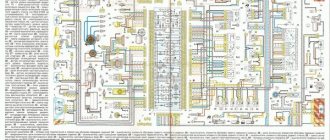
1 – relay-interrupter for the parking brake warning lamp; 2 – tachometer with voltage stabilizer; 3 – instrument cluster lighting lamp; 4 – temperature indicator; 5 – BSK control unit; 6 – fuel level indicator; 7 – resistor 50 Ohm, 5 W; 8 – control lamp “CHECK ENGINE” for the toxicity reduction system; 9 – control lamp for high beam headlights; 10 – side light indicator lamp; 11 – backup warning lamp; 12 – warning lamp for unfastened seat belts; 13 – control lamp for left direction indicators; 14 – resistor 470 Ohm, 0.25 W; 15 – electronic voltmeter; 16 – control lamp for right direction indicators; 17 – warning lamp for emergency oil pressure; 18 – fuel reserve warning lamp; 19 – control lamp for the carburetor air damper; 20 – indicator lamp “CHECK ENGINE” for the fuel injection system; 21 – parking brake warning lamp.
Instrument cluster wiring diagram after 1996
1 – tachometer; 2 – instrument cluster lighting lamp; 3 – temperature indicator; 4 – BSK control unit; 5 – fuel level indicator; 6 – control lamp “CHECK ENGINE” for the toxicity reduction system; 7 – control lamp for high beam headlights; 8 – side light indicator lamp; 9 – backup warning lamp; 10 – warning lamp for unfastened seat belts; 11 – control lamp for left direction indicators; 12 – battery charge indicator lamp; 13 – control lamp for right direction indicators; 14 – warning lamp for emergency oil pressure; 15 – fuel reserve warning lamp; 16 – control lamp for the carburetor air damper; 17 – indicator lamp “CHECK ENGINE” for the fuel injection system; 18 – parking brake warning lamp; B1 – resistor 91 kOhm; B2 – resistor 50 Ohm, 5 W.
Model selection
It is best to install an imported fuel pump on the VAZ 2110 injector, capable of delivering a performance of up to 7 atm. It will not only last much longer, but will also ensure better and longer operation of the injector and improve the quality of the mixture at the outlet of the nozzle.
You should know that Bosch fuel pumps usually differ only in length, location of terminal connectors, and sometimes in the diameter of the housing. Therefore, it is advisable to either go shopping with an old device, or make some minor modifications at home.
To avoid buying a fake, keep in mind that any Bosch gas pump is packaged in very durable packaging. The bag contains purified gasoline in which the device is immersed. If you smell it, it means the seal is broken, corrosion may begin inside the pump, it’s better not to buy one.
Pinout of the dashboard of VAZ2110, 2111, 2112
- fuel reserve warning lamp;
- dashboard lighting lamps;
- right repeater indicator lamp;
- left repeater indicator lamp;
- VAZ plug block;
- coolant temperature sensor;
- indicator lamp for external lighting;
- carburetor air damper warning lamp;
- oil pressure warning lamp;
- handbrake indicator lamp;
- battery charge indicator lamp;
- VAZ tachometer;
- indicator light “CHECK ENGINE”;
- speedometer dashboard;
- brake fluid level warning lamp;
- hazard warning lamp;
- high beam indicator lamp;
- fuel level indicator.
Pinout of the dashboard of VAZ2113, 2114, 2115
There are 26 contacts on the VAZ-2114 instrument panel, each of which is responsible for the operation of the indicators of this panel. If a plus is supplied to the panel, then each contact displays information about the state in which the car is currently located.
White block (X1)
Red block (X2)
- Housing (weight) - black
- To ambient temperature sensor - cyan-magenta
- Tachometer (low voltage input from ECU) - brown/purple
- Fuse F16 (to terminal 15 of the ignition switch) - orange
- Tachometer (high voltage input from coil) - yellow
- Housing (weight) - black
- To fuse F3 of the mounting block (+battery) - white-purple
- Instrument lighting control - white
- Coolant temperature sensor. - green-white
- Turn signal RIGHT - blue
- To fuse F10 of the mounting block - brown
- Turn signal LEFT - blue-black
- Brake fluid level - pink-blue
- Check Engine Light to ECU Controller - White-Purple
- To the trip computer - brown
- To the ECU controller - pink and black
- Speed sensor - gray and yellow
- To the fuel gauge sensor - orange
- To the fuel gauge sensor - pink
- To the parking brake switch - brown-blue
- Fuse F14 of the mounting block - green-black
- Alternator terminal "D" through fuse panel - brown and white
- Hazard switch
- Oil pressure sensor - blue
- To terminal “50” of the ignition switch - purple
In addition, special indicators and signal sensors are installed on the instrument panel, and the panel itself is controlled by a special electronic unit. Having disassembled the instrument panel, you can see that there are two pads inside it: red and white. And all inputs, outputs and fuses are connected to the plug. If the sensors fail, they will need to be replaced. It is also better to replace damaged or oxidized wires. Indicator lights, like any other, sometimes burn out. Undoubtedly, they need to be replaced with whole ones. Along with them, the lamp sensor often burns out.
VAZ 2114 instrument panel connection diagram
- rear window heating switch;
- rear fog lamp switch;
- switch for headlights and direction indicators;
- mounting block;
- wiper switch;
- fog light switch;
- on-board control system display unit;
- instrument panel harness block to additional harness;
- instrument cluster;
- instrument panel harness connector to the on-board computer harness;
- instrument panel harness connector to the ignition system harness;
- instrument panel harness connector to the side door harness;
- fuse 16 A;
- fuse 16 A;
- ignition switch;
- lighting switch;
- heater electric motor;
- additional resistance of the heater electric motor;
- ignition switch unloading relay;
- rear fog light relay;
- starter relay;
- socket for connecting a portable lamp;
- cigarette lighter;
- instrument panel harness connector to the glove compartment lamp wiring harness;
- illuminator;
- illuminator;
- illuminator;
- heater switch;
- instrument lighting regulator with rheostat;
- brake light switch;
- horn switch;
- hazard switch;
- heater control lamp;
- fuse 16 A;
- seat heating relay;
Another variant of the connector pinout diagram
- checking the brake fluid level indicator. If you apply +, the brake light will light up. You can connect it to the red wire of the ignition switch, then, just like on 2110/2114, the lamp will be checked when the starter is turned on.
- Hazard warning lamp will light up when + is applied.
- high beam lamp, connect to the green-black wire.
- fuel level indicator, connect to the pink-red wire.
- to the speed sensor.
- speed signal output to the on-board computer. If there is one, then take the speed signal from this contact.
- Brake fluid level indicator, connect to the pink-blue wire near the lamp above the cigarette lighter. In the VAZ-2107, the lamp works the other way around: the sensor connects the lamp to ground and it lights up. You will have to either leave the lamp where it is, or in the new device, solder the lamp to + and swap the diodes (in this case, to check the lamp, pin 1 must be connected to ground, for example, to the parking brake lamp), or remove the black wire from the sensor on the tank, and connect instead the orange one from the EPHH unit, or the blue one from the ignition coil, while the diode in the wiring (between the beard and the glove compartment) must be disconnected; if this is not done, there will be a short circuit.
- left turn lamp, connect to the blue-black wire of the steering column switch block.
- Right turn lamp, connect to the blue wire of the steering column switch pad.
- instrument lighting, connect to the white wire.
- ground, connect to the black wire.
- power supply of devices, connect to the orange wire.
- if the device is simple (without microcircuits, etc.), then connect it to the blue-red wire (fuel reserve lamp), if there is a display under the tachometer, then connect it to the temperature sensor (take from a VAZ-2114, one contact to the device, the other to ground, place it either in the passenger compartment or in the engine compartment, but far from the engine and so that the wind does not blow).
- ground, connect to the white-black wire.
- low-voltage tachometer input (from the ECM), connect to the brown-blue wire.
- high-voltage tachometer input (from the coil), connect to the brown-blue wire.
- If there is a display under the speedometer, then connect it to the red and white wire at the brake light switch.
- coolant temperature gauge, connect to the green-white wire.
- outdoor lighting lamp, connect to the yellow wire.
- carburetor choke cover lamp, connect to the gray-orange wire.
- go to the ECM lamp. If the machine is injection, then connect one of the contacts to the orange wire, and the other to the remaining one.
- go to the ECM lamp. If the machine is injection, then connect one of the contacts to the orange wire, and the other to the remaining one.
- power supply of devices, connect to the orange-blue wire.
- handbrake lamp, connect to the brown wire.
- battery charge lamp, connect to the brown-white wire.
- low oil pressure lamp, connect to the gray-blue wire.
Methods for troubleshooting
Troubleshooting is not a complicated process and even novice car enthusiasts can do it (the author of the video is Avtoelektika VC).
First of all, you should check the integrity and condition of the wiring.
Using a multimeter, you need to test the wiring. Damaged or torn sections should be replaced intact or soldered. If there are traces of oxidation processes on the contacts, they need to be cleaned.
If the LEDs burn out, they need to be replaced in pairs. If the breaker fails, it must be replaced with a new one, as it cannot be repaired. Before replacing, turn off the vehicle's power by removing the negative terminal from the battery. Then disconnect the power wires from the breaker. Next, you need to loosen the lock nut and unscrew the main nut securing the switch to the bracket.
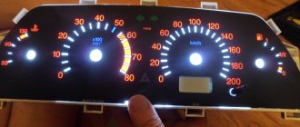
Instrument panels VAZ VDO (LED)
You can install a more beautiful and convenient panel with LED indicators, the so-called VDO panel. Here VDO is the panel manufacturer.
| Connecting VDO on a Kalina car | ||
| 1 | Pink-white | To electric power steering |
| 2 | Blue and white | To the hazard warning indicator |
| 3 | Gray-blue | To emergency oil pressure sensor |
| 4 | Brown blue | To the parking brake switch |
| 5 | Yellow-blue | To the immobilizer control unit |
| 6 | Black | To the airbag control unit |
| 7 | Yellow | To the outside light switch |
| 8 | Blue | To the right turn signal switch |
| 9 | Blue with black | To left turn signal switch |
| 10 | White-blue | TO ECU |
| 11 | . | To brake pad wear sensor |
| 12 | . | To seat belt sensor |
| 13 | Black | To the traction control control unit |
| 14 | Red-blue | “RESET” key on the steering column switch |
| 15 | Pink-blue | To brake fluid level sensor |
| 16 | Black | To ABS |
| 17 | Green | To the high beam switch |
| 18 | White | To the instrument cluster light control |
| 19 | Brown | Panel weight |
| 20 | White-red | Terminal “30” |
| 21 | Orange | Terminal “15” |
| 22 | Yellow-red | To fuel flow sensor |
| 23 | Orange-white | MK key “forward” |
| 24 | White black | MK key “back” |
| 25 | Black and white | Outside temperature sensor (-) |
| 26 | Yellow-green | Outside temperature sensor (+) |
| 27 | Pink | Fuel level sensor |
| 28 | Grey | Speed sensor |
| 29 | Green-white | Coolant temperature sensor |
| 30 | Brown-red | Tachometer (low voltage) |
| 31 | . | Official. Panel diagnostics. |
| 32 | Brown-white | Terminal “L” of the generator relay regulator |
Stories from our readers
“Fucking basin. "
Hi all! My name is Mikhail, now I’ll tell you a story about how I managed to exchange my two-wheeler for a 2010 Camry. It all started with the fact that I began to be wildly irritated by the breakdowns of the two-wheeler, it seemed like nothing serious was broken, but damn it, there were so many little things that really started to irritate me. This is where the idea arose that it was time to change the car to a foreign car. The choice fell on the melting Camry of the tenth years.
Yes, I had matured morally, but financially I just couldn’t handle it. I’ll say right away that I am against loans and taking a car, especially not a new one, on credit is unreasonable. My salary is 24k a month, so collecting 600-700 thousand is almost impossible for me. I started looking for different ways to make money on the Internet. You can’t imagine how many scams there are, what I haven’t tried: sports betting, network marketing, and even the volcano casino, where I successfully lost about 10 thousand ((The only direction in which it seemed to me that I could make money was currency trading on the stock exchange, they call it Forex. But when I started delving into it, I realized that it was very difficult for me. I continued to dig further and came across binary options. The essence is the same as in Forex, but it’s much easier to understand. I started reading forums, studying trading strategies. I tried it on a demo account, then opened a real account. To be honest, I didn’t manage to start earning money right away, until I understood all the mechanics of options, I lost about 3,000 rubles, but as it turned out, it was a precious experience. Now I earn 5-7 thousand rubles a day. I managed to get the car buy after half a year, but in my opinion this is a good result, and it’s not about the car, my life has changed, I naturally quit my job, I have more free time for myself and my family. You’ll laugh, but I work directly on the phone)) If If you want to change your life like me, then here’s what I advise you to do right now: 1. Register on the site 2. Practice on a Demo account (it’s free). 3. As soon as you get something on the Demo account, top up your REAL ACCOUNT and go to REAL MONEY! I also advise you to download the application to your phone, it’s much more convenient to work from your phone. Download here.
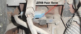
The essence of the modification : to differentiate the masses, and this can be done in two ways.
Method 1 : bite off the wire connecting the ground and connect it to the metal frame with a separate wire. Wire extension can be done by crimping into a transition tinned copper tube. Photos of the process were sent by Dmitry Larionov:
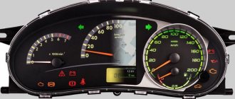
VAZ instrument panel indicators - explanation
- coolant temperature gauge.
- tachometer;
- left turn signal indicator lamp;
- right turn signal indicator lamp;
- speedometer;
- fuel level indicator;
- fuel reserve warning lamp;
- side light indicator lamp;
- service brake system warning lamp;
- high beam indicator lamp;
- reset button;
- mileage indicator;
- warning lamp for turning on the hazard warning lights;
- "check engine" warning light;
- time and temperature indicator;
- battery charge indicator lamp or battery lamp;
- parking brake warning lamp;
- oil pressure warning lamp;
- reserve.
Repair or replacement of the VAZ dashboard
If on a car on the instrument panel none of the indicators installed on it work (speedometer, odometer, tachometer, fuel level and coolant temperature indicators), then the first thing the driver will have to do is check the integrity of fuse F3, which is located in the mounting block . If it has burned out, then before replacing it, you need to find the reason why it burned out, otherwise the newly installed new fuse will have the same fate as the previous one. Most often, fuses burn as a result of a short circuit.
Even if the fuse is intact, then do not be lazy to take it out and check the condition of the contacts. There are cases when the contacts oxidize, and the electrical circuit in this place is interrupted. After making sure that the fuse is intact, the next step is to check the ignition relay, which is located inside the car to the left of the steering column. It is attached to a pin upside down. In the block where this relay is inserted, you can try to short-circuit the power wires using a jumper. If the instrument panel comes to life, the ignition relay will have to be replaced.
If the ignition relay is working properly, there are only two possible reasons for the instrument panel not working: the ignition switch and the mounting block. Before installation on the VAZ-2109 car, the ignition relay and lock contacts often burned out and had to be cleaned by disconnecting the contact group from the lock itself. After changes were made to the principle of supplying voltage to the ignition switch, its contacts began to burn very rarely, but the likelihood of this phenomenon still remained. On the mounting block, in its board, tracks may burn out; in order to see this, the mounting block will have to be removed from the car.
In addition to the reasons listed above, which can lead to failure of the instrument panel, it is also necessary to check the reliability of the fastening of the ground wire. Most common problems:
- burnout of incandescent lamps or failure of the LED group;
- oxidation of connectors;
- electrical wiring fault;
- failure of the fuse box;
- damage to the common contact board;
- no weight on the body (minus) or damage to the dimensions system.
To find a fault, you must use diagnostic equipment, a tester or a voltmeter. If a breakdown is found, you can begin repairs.
What is mass in a car?
“Ground” is the wire that connects the negative terminal of an electrical element (for example, an electromagnet) to the body of the product in which it is installed. ... The “ground” can be not only the wire, but also the body of the electrical element itself.
Interesting materials:
How to make a round hole in wood? How to make a socket box in a tree? How to mark eyebrows? How does the 1st action of a thunderstorm end? What happens if you reset your iPhone? What happens if you don’t register at the military registration and enlistment office? What happens if you take a screenshot on Instagram? What happens if you give an injection into the sciatic nerve? What happens if you do Wipe data? What happens if the angle of incidence is set to 0?
Removing the car dashboard
- Using a Phillips screwdriver, remove the three screws that secure the center console;
- remove the cover, the protrusion located at the bottom, remove the protrusion from the bracket;
- Using a nozzle, unscrew the five screws located in the console on the right and remove the screen;
- Disconnect the terminal with the (-) sign from the battery. If there is a radio receiver, you need to remove it, remove the plug from the shield;
- Disconnect the wires coming from the cigarette lighter, remove the cartridge;
- Using a narrow screwdriver, remove the handle from the levers;
- pull the handle towards the heating and fan switch;
- unscrew the two screws above the panel and the two located under it using a screwdriver;
- unscrew the screw located behind the panel;
- Also unscrew the two self-tapping screws securing the cover;
- disconnect the harness and wire connectors. To avoid confusion when installing the panels, you should mark the order in which they are connected;
- unscrew the fastening bolts;
- unscrew the two self-tapping screws, those that secure the bottom bracket using an 8 key;
- unscrew the self-tapping screw securing the light guide and remove it;
- Also unscrew the screws securing the heating unit;
- remove lamp sockets;
- after removing the external parts, remove the decorative insert;
- unscrew all nuts with a 21 key;
- hydrocorrector, remove its lamp;
- Unscrew the screws that are attached to the cross member on the left.
- Finally, the panel itself is removed. The panel is assembled accordingly in the reverse order.
In general, the repair work is quite doable even with your own hands, but before starting dismantling work, you need at least a pinout mapped on paper, otherwise it will be difficult: you will need to “trace” every wire and every connection that is on the “path” from devices to the power button.
Source
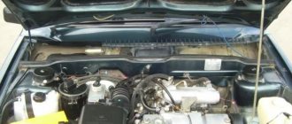
Video instructions: VAZ 2110 where the mass of the fuel pump is located
13 years on the forum
From: Belgorod
Car: VAZ 21120, opal, 2001, 1.5 16V, M 1.5.4N
Added: January 22, 2010 23:30 Message title: Where is the mass of the fuel pump? –> In general, I started it today and warmed it up. bam, it started, I started it, all the signs of a non-working fuel pump, I listened, it’s definitely not working. It was -17 outside at that time. I was scared and wasn’t even standing near the house yet. In short, a tester in a car is a thing. I called, there is no mass! At -17 I didn’t want a driver, so I threw in an additional temporary wire and drove off. So, I don’t want to disassemble half the car, tell me where the fuel pump gets the power? Return to top krot 21224
9 years on the forum
Added: January 22, 2010 23:35 Message title: –> I don’t agree with the fact that you’ll have to disassemble less than half the car. (just kidding), but the weight of the fuel pump was screwed at the factory to one of the bolts securing the handbrake. I discovered it myself when I was changing the handbrake lever, unscrewed the handbrake and decided to drive the car into the garage, well, to make it easier to install, bam it wouldn’t start, I started digging around and found it. mainly to the rear handbrake bolt which is closer to the driver's seat. Return to top maxxic
13 years on the forum
From: Belgorod
Car: VAZ 21120, opal, 2001, 1.5 16V, M 1.5.4N
Added: January 22, 2010 23:38 Message title: –> Damn it. Dunduk I. ))) I recently unscrewed the handbrake, I haven’t even put everything back together yet. And I saw it.. I forgot completely.. in a hurry I screwed on the handbrake and drove off.. it would have been better if it didn’t work right away.. apparently it got caught right away somewhere, I’ve been driving for a week “without the weight of the fuel pump” Return to the beginning krot 21224
9 years on the forum
Added: January 22, 2010 23:48 Message title: –> Perhaps the bolt was not tightened all the way, maybe it just needs to be tightened. Return to top maxxic
13 years on the forum
From: Belgorod
Car: VAZ 21120, opal, 2001, 1.5 16V, M 1.5.4N
Added: January 23, 2010 09:48 Post title: –> krot 21224 wrote:
Perhaps the bolt is not fully tightened, maybe it just needs to be tightened. no, I completely forgot about it (the mass), the wire is lying somewhere under the noise, unfastened.. today I’ll try to pull it out from there and screw it on. Return to top where is the mass of the VAZ 2110 fuel pump