Yesterday, in the comments to one of my articles, I came across a question about the ignition coil or ignition module. I’m used to calling it an ignition coil, so we’ll stop there. Moreover, in fact, these are coils. In general, let's start figuring out where the ignition coil is, how to remove it, how to put it on, how to check it with a multimeter, and so on. Fasten your seat belts and let's go.
Signs of a bad ignition coil!
Description and purpose
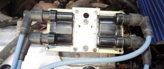
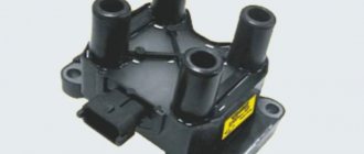
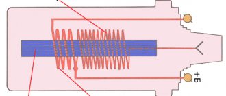
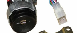
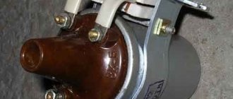
Ignition coil VAZ 2114 8 valves, VAZ 2113, VAZ 2115 are two two-output ignition reels mounted in a single casing. It is designed to convert low on-board voltage (12 volts) into high sparking voltage. Sparking occurs in two pots at once (1-4 and 2-3). The ignition solenoid is connected to the spark plugs by high-voltage wires with permanent tips.
| 1 — ignition coil VAZ 2114 |
| 2 - package of high-voltage wires |
Below, in the figure, the design of the ignition coil of the VAZ 2114 8 valves is presented
Important ! Crankshaft sensor VAZ 2114
What should I do if the problem remains after replacing the module?
If, after performing the repair, problems in the operation of the MH remain, then there is a possibility that the cause of the problem was not in the module. It is necessary to diagnose the remaining elements of the ignition system.
Spark plugs and ignition system
Features of checking spark plugs and other components:
- Before dismantling the devices, it is necessary to disconnect the ends of the high-voltage cables. Their condition is checked for damage. Defects in the tips often lead to malfunctions in the spark plugs. If there is damage, the wires are replaced. It is also necessary to assess the condition of the “high-voltage workers” themselves. They are not allowed to have any defects or damage to the insulation.
- After disconnecting the tips, the spark plugs are dismantled and a special spark plug wrench is used to unscrew them.
- After dismantling, the condition of the devices is assessed. The color of the parts must be brown; carbon deposits and soot on the electrodes are not allowed. If there are uncharacteristic marks, the devices are cleaned using a metal brush or fine-grained sandpaper. For a better effect, the electrodes of the candles can be heated on the stove.
- The condition of the gap between the part and the electrode element is checked. If it is too large, this indicates that the device is not working correctly. The spark plugs will need to be replaced.
The principle of operation of the ignition coil VAZ 2114 8 valves, model 2111-3705010-02
The current in the primary windings of the ignition coils is controlled by a controller that uses information about the engine operating mode received from the engine control system sensors. To switch the primary windings of the ignition coils, the controller uses two powerful transistor valves.
From the ignition coil of the VAZ 2114 8 valves, a high voltage pulse is supplied to two cylinders at once: 1 - 4, 2 - 3. In one cylinder the compression stroke ends (working spark), and in the second the exhaust stroke (idle spark) occurs.
Due to the constant direction of current in the primary and secondary windings, the sparking current of one spark plug always flows from the central electrode to the side electrode, and the second - from the side to the central one.
The ignition coil of the VAZ 2114 injector 8 valves works according to the following principle. The vehicle's electrical system voltage is supplied from the ignition switch to contact “15” of the ignition coil. Next, the controller switches the pulse to terminal “1b”, the circuit of the primary winding of the ignition coil, as a result of which the secondary winding outputs high voltage to the spark plugs of cylinders 1 and 4. And the controller switches the pulse to terminal “1a”, the circuit of the primary winding of the ignition coil, as a result which causes the secondary winding to output high voltage to the spark plugs of cylinders 2 and 3.
| Deciphering the engine ignition system with an ignition coil VAZ 2114 | |
| Position number on the VAZ 2114 diagram | Explanation of position |
| 1 | accumulator battery; |
| 2 | main relay; |
| 3 | ignition switch; |
| 4 | spark plug; |
| 5 | ignition coil VAZ 2114 8 valves model 54.37005; |
| 6 | controller; |
| 7 | crankshaft position sensor; |
| 8 | master disk. |
Possible reasons for failure of the ignition module
Before repairing the main part in the car’s ignition system, you need to understand the nature of the problem. To do this, the consumer must be aware of the signs of a malfunction, as well as the causes of the breakdown.
The main reasons for device failure
Causes of problems:
- The ignition system uses spark plugs that do not match the vehicle parameters. They may not have the gap specified by the manufacturer. Also, the spark plugs themselves may not be working or dirty; this can be determined by visual diagnostics. If there are traces of carbon deposits on the devices, they must be removed.
- Malfunctions in the operation of the MH can arise as a result of frequent spark checks. At the time of diagnosis, a high load is placed on the device. If it appears frequently, it will lead to equipment failure or incorrect operation.
- The ignition module in the VAZ 2114 operates with the high-voltage cables disconnected. This also leads to device failure. The products themselves may be damaged, which affects the functioning of the engine as a whole.
- The device operates under severe vibration conditions. Their impact may be due to poor quality fixation of the module in the seat. As a result of vibrations, the factory soldering inside the equipment structure is damaged. This leads to its incorrect operation.
- The contact inside the plug with the low-voltage cables is broken.
- Initial use of a defective device or module with poor build quality. This factory defect can only be eliminated by replacing the mechanism; repairing the equipment is pointless.
- Moisture getting inside the case. This problem is unlikely, but exposure of the device to liquid may cause it to short out and break.
Signs of coil malfunction
The main symptoms of a malfunction in the VAZ 2114 ignition module:
- Difficulties arise when trying to start the engine. Starting the car engine may be difficult due to the fact that there is no spark on a spark plug or several.
- When idling or parking with the internal combustion engine running, the speed of the power unit floats. Their change is not associated with pressing the gas pedal and other third-party factors. This happens randomly.
- There are dips in the power of the car's engine. This is especially felt when driving uphill or sharp acceleration. Problems can also occur when driving on a flat road.
- Several cylinders stopped working. Usually these devices operate in pairs, so elements 1-4 or 2-3 could fail. Non-working cylinders may be indicated by “triple movement” of the engine.
- A “Check Engine” warning light appeared on the dashboard.
If the ignition module malfunctions, problems will appear not only in engine operation, but also when starting it.
The “Simple Opinion” channel, using the Lada Priora car as an example, spoke in detail about the symptoms that appear in the operation of the ignition modules.
Explanation of the ignition coil designation (Catalogue number) - 2111-3705010;
The designation of a part or assembly is a unique number in a single form. Assigned to only one part. The numbering of designations for assembly units and parts is carried out according to a unified seven-digit system. Designation - 2111-3705010-02 is deciphered as follows. The first four digits before the dash indicate the model of the base car or engine, chassis, body. In our case: 2111 is the engine model. The first two digits after the dash indicate the group number, in this case 37 - electrical equipment. The next two digits are the subgroup number. In our case, 05 is the ignition coil. The last three digits of the seven-digit number indicate the serial number of the part. The last two digits after the second dash indicate the interchangeability of the part. ХХХХ-ХХХХХХ-00 (to-09) - interchangeable. ХХХХ-ХХХХХХХ-10 (up to 19) are interchangeable with each other but not interchangeable with ХХХХ-ХХХХХХХ-00 (up to-09) and so on.
The part designation is applied to the body of the part. It helps determine the interchangeability and suitability of a particular part when purchasing and searching for it.
For what malfunctions is it possible to repair the device?
Due to the fact that the ignition module by design includes a connection of two coils, it is difficult to repair. If there is a break or breakdown, as well as melting of the turns, the problem can be solved by replacing the device. This applies to any damage that appears inside the coils. The only option to correct the situation without replacing the device is to repair the damage to the solder joint.
Ignition module repair process
The repair procedure is carried out after preparing all tools and materials:
- a set of socket wrenches, you will need a tool for 10, 13 and 17;
- hexagon 5;
- flat head screwdriver;
- soldering iron with aluminum and flux;
- nail polish;
- multi-core conductors.
Restoring the ignition module operation is done as follows:
- The key is installed in the switch. The engine starts. Then you need to move the contact elements on the module to make sure they are not working.
- The power unit stops. The module is being removed.
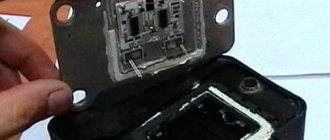
- The device body is cleaned from dust. To disassemble, you need to open the case; this is done by prying it off with a screwdriver. Inside the device there is a board on which there is a silicone film; you need to get rid of it.
- Aluminum is removed from high-voltage contact elements. Old wires are removed.
- The next step will be soldering new conductors to the circuit. To do this, the surface of the collector device is cleaned from traces of plaque. Then the board must be installed on an electric stove and heated to approximately 200 degrees. As the temperature increases, a slight burning smell may be heard. This is not a problem for the circuit; heating it will simplify the soldering procedure.
- Then soldering is done. Using a soldering iron, flux and aluminum, the ends of the conductors must be connected to the ignition module. All contact elements of the conductors that are connected to the circuit must be treated with nail polish.
- Then the device is assembled in the reverse order and installed in the seat. After installation, the power unit starts up. If the repair solves the problem, then using a sealant, the device is fixed in place.
- If a transistor or switching device fails, then these components cannot be repaired, but they can be replaced. To do this, the parts are removed from the board and replaced with new ones.
Analogues of the VAZ 2114 ignition coil type 2111-3705010-02
Analogs of the ignition coil VAZ 2114 injector 8 valves, model 2111-3705010-02 , based on the M7.9.7 controller or its analogues are the following electrical devices:
| Bosch ignition coil model F000 ZS0 211; |
| Ignition coil model 2111-3705010 from Baker. |
Important ! Temperature sensor VAZ 2114
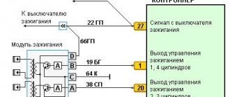
Pinout of ignition coil VAZ 2114 8 valves model 2111-3705010-02 (54.37005)
The figure below shows the pinout of the VAZ 2114 ignition coil 8 valves model 2111-3705010-02 (54.37005). The arrows on it indicate the contacts and their purpose.
Schematic diagram of engine control with an ignition coil
| Deciphering the schematic diagram of engine control with an ignition coil VAZ 2114 | |
| Position number on the VAZ 2114 diagram | Explanation of position |
| 1 | ignition switch; |
| 2 | main relay; |
| 3 | battery; |
| 4 | atmospheric filter; |
| 5 | diagnostic connector; |
| 6 | dashboard; |
| 7 | tachometer; |
| 8 | check lamp; |
| 9 | speedometer; |
| 10 | immobilizer sensor with indicator; |
| 11 | immobilizer manual device; |
| 12 | electric fan of the engine cooling structure; |
| 13 | electric fan relay; |
| 14 | controller; |
| 15 | DTOZH; |
| 16 | ignition coil VAZ 2114 8 valves, VAZ 2113, VAZ 2115; |
| 17 | spark plug; |
| 18 | DPRV; |
| 19 | sprayers; |
| 20 | throttle assembly; |
| 21 | TPDZ; |
| 22 | DMRV; |
| 23 | empty control; |
| 24 | Lambda probe; |
| 25 | car speed sensor; |
| 26 | DPKV; |
| 27 | DD; |
| 28 | crankshaft pulley; |
| 29 | gasoline filter; |
| 30 | petrol pump relay; |
| 31 | gasoline tank; |
| 31 | gasoline unit; |
| 32 | two-way valve; |
| 33 | gravity throttle; |
| 34 | reverse breather; |
| 35 | check valve; |
| 36 | adsorber purge throttle; |
| 37 | adsorber; |
| 38 | separator. |
Important ! DMRV VAZ 2114
Checking the ignition coil of a VAZ 2114 injector 8 valves
Checking the ignition coil of the VAZ 2114 model 2111-3705010-02 (54.37005) is carried out in the following sequence:
- Disconnect the terminal block of the ignition reel;
- Turn on the ignition, use a multimeter to measure the voltage between terminal 15 and the housing, for the ignition reel, or terminals C and D (for the ignition module) of the terminal block with a cable harness. The voltage must be at least 12 V. When the voltage does not go to the terminal block or it is less than 12 V, the battery is discharged, the power line is broken, or the controller is broken. You can verify that the ignition module is working by replacing it with a known working one. The ignition coil can be checked with an ohmmeter.
- Remove the ignition coil;
- Using a multimeter, we measure the electrical resistance between the middle terminal 15 and the bracket. The meter must indicate the absence of the short of the first winding of the solenoid on the housing. In order, we measure the electrical resistance between the middle terminal 15 and the outer terminal - 1a and 1b. The resistance of all the first windings of the bobbin must be around 0.5 Ohm. When we measure small electrical resistance sizes, about 1 Ohm, we need to take into account the internal resistance of the meter, which can be measured by short-circuiting the multimeter probes.
- Using a tester, we measure the resistance between the high-voltage terminals of the solenoid 1 and 4, and then 2 and 3. The resistance of the windings should be around 5.4 kOhm.
How to check a coil for breakdown
You can check for breakdown of the ignition coil in one of 5 ways, but as a rule, the average car owner has the opportunity to use only three of them. The first is a visual inspection, because often the breakdown site is visible to the eye; the second is a check with a multimeter, and the third, and the most reliable quick method, if nothing is visually noticeable, is to use a simple ignition system tester (it’s easy to do it yourself).
Ignition system diagnostics
Recommendations for diagnosing the ignition system (spark plugs, wires, coils, module). Instructions on how to check the ignition units of a car with your own hands Read more
To check the operation of the ignition system, first of all, it makes sense to use a program to read errors from the ECU. Usually in such cases it shows errors from the groups P0300 and P0363, indicating misfire in one of the cylinders. However, please note that in this case, errors can be caused not only by faulty coils or spark plug tips. Therefore, in order to make sure that the fault is with one of them, it makes sense to move the problem unit to another cylinder, erase errors from the ECU memory and carry out diagnostics again.
If the problem is in the coil (we are talking about an individual coil), then the situation with errors will repeat, but indicating a different cylinder. True, when this is precisely a breakdown of the coil, and such that gaps appear, then you can already understand by the vibration of the engine, see with your eye a broken insulator track, or even hear a characteristic crackling sound with your ear. Sometimes at night, in addition to a crackling sound, you can also see a spark appearing.
Visual inspection
The next way to determine a breakdown of the ignition coil is to dismantle it and visually inspect it. As practice shows, on the coil body it is usually not difficult to find the very “path” of breakdown along which the spark “sews”. Or you should pay attention to chips, potholes, and geometry violations in the reel body that were not there before.
Measuring parameters
There are two mandatory methods for checking the condition of the ignition coil - checking for spark and checking the insulation resistance of both windings (low and high voltage). To measure the parameters, you will need a working spark plug and a multimeter with the ability to measure insulation resistance. But the most reliable way is to use a spark generation tester, only with a slight modification, so that you can move the conductor along the coil body and look for the weak point of the insulation that breaks through.
Homemade spark tester
The most interesting and reliable method for checking the breakdown of the ignition coil is to use a special homemade probe. It helps when the defect is not visible visually, checking the resistance of the windings did not reveal the problem, but there is no way to use an oscilloscope. To make a spark tester you will need:
The manufacturing process sequence consists of the following steps:
How to determine ignition coil breakdown with a spark tester
After a homemade tester has been made to find the location of the penetration, the procedure itself must be performed according to the following algorithm:
Finding a breakdown using a homemade tester
The verification method is simple and universal. With its help, you can not only find the place where the spark “sews” across the body, but also determine the general operating condition of the ignition coil itself.
This is done by adjusting the gap between the spark plug electrode and the wire on the syringe plunger. At the initial stage, a minimum gap is set with a value of about 1.2 mm and gradually increases. The value of the gap at which the spark disappears depends on the engine size, the type and condition of the ignition system and other factors. On average, for engines with a volume of about 2 liters or less, the distance at which the spark should disappear is about 12 mm, but this is conditional. In general, when checking all individual ignition coils, you can simply compare their operation with each other and identify the faulty element, if present.
Literature on passenger cars VAZ 2114, 2113, 2115 and their modifications
Here you can download the necessary books required for the operation of passenger cars of the VAZ 2114, 2113, 2115 family and their modifications.
| 1 | Reanimation of a car in road conditions VAZ 2113, 2114, 2115. | 2007 | 49 pp. | Size - 1.71 MB | Format - djvu |
| 2 | OPERATING MANUAL FOR VAZ-2113, -2114, -2115 CARS AND THEIR MODIFICATIONS | 2002 | 88 pp. | Size - 751 KB | Format - pdf |
| 3 | Distributed fuel injection systems for VAZ cars - design and diagnostics | 2003 | 128 pp. | Size - 1.67 MB | Format - pdf |