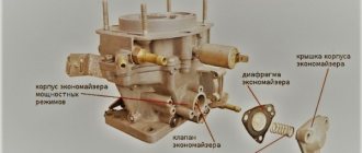
The ignition module on injection VAZ 2109 is deservedly considered one of the most complex electrical components. If the injectors have a module, then the carburetors have the simplest coil.
The actual, but incredibly important task of the module is the generation of high voltage current, which can reach 30 thousand watts. The current follows high-voltage wires to the spark plugs, which create a spark to ignite the air-fuel mixture.
The classic ignition coil is one of the components of the module, so the system works on a much more complex principle than on carburetors.
The principle of operation of a four-stroke power plant
You can understand why it is important to connect high-voltage wires correctly if you study the principle of operation of the power plant. The carburetor or injector of the VAZ-2109 operates on approximately the same principle, since both power plants are four-stroke.
- First, the cylinder volume is filled with the fuel mixture and exhaust gases. This process is called "inlet".
- The engine then goes into compression. With it, the valves are closed, and the crankshaft and connecting rod move the piston upward. The mixture of fuel and air is transferred to the combustion chamber.
- During the expansion stage, the ignition is switched on and a spark appears. It ignites the fuel mixture, resulting in the formation of gases. They put pressure on the piston, causing it to move down. This force is transmitted through the connecting rod to the crankshaft.
- The process is completed by the “release” of exhaust gases through the exhaust system.
In order for the engine to operate smoothly and without jerking, the processes must take place in a certain order. This, first of all, concerns the order in which the cylinders are put into operation.
Sereshka 05.12.2010 - 18:01
Kiel Blinton (05.12.2010 - 17:56)
:
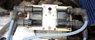
Good day everyone! Forgive me if the topic is button accordion, but there is no one else to ask. Question - I have an engine 2110 engineer, I bought high-voltage wires and foolishly removed the old ones, but I didn’t remember the connection sequence. If I am facing the car, then the numbering of the spark plugs is 1 2 3 4. But how are they all connected to the square ignition module? If anyone knows, please explain or draw a diagram, please.
There should be numbers on the module itself.
Engine workflow through cylinders
The cylinders are activated as follows:
- In the first there is an upward movement. The gases expand and the mixture of air and fuel burns.
- In the third, to carry out the compression procedure, the piston rises.
- In the fourth, “injection” occurs - the piston moves down and at the same time a mixture of air and gasoline enters the cylinder.
- In the second cylinder, the piston rises and takes the upper position so that gases escape through the valve system. After which the exhaust gases are removed from the power unit.
Based on the principle of operation of the cylinders, their activation diagram looks like this: 1-3-4-2. It is important to connect them correctly so that the cylinders work in that order.
Wiring diagram for VAZ 2110 carburetor
In the instrument panel wiring harness, the second ends of the wires of white, black, orange, white with a red stripe and yellow with a blue stripe are connected to each other at the same points. The bends of the wires at the points of entry into the harness indicate the direction of their laying in the bundle.
See the complete diagram in one file below (click to enlarge):
1 – headlight 37 – instrument cluster 2 – front brake pad wear sensor 38 – rear fog light switch 3 – fan motor switch 39 – fog light indicator lamp 4 – engine cooling system fan electric motor 40 – rear window heating indicator lamp 5 – sound signal 41 – clock 6 – generator 42 – rear window heating switch 7 – oil level sensor 43 – steering column switch 8 – carburetor solenoid valve control unit 44 – block for switching wires when installing headlights of another type 9 – heater controller 45 – switch instrument lighting 10 – recirculation valve switch 46 – ignition switch 11 – illumination lamp for heater control levers 47 – connectors for connecting the headlight cleaner wiring harness 12 – switch 48 – socket for a portable lamp 13 – carburetor limit switch 49 – directional light 14 – control sensor oil pressure lamps 50 – brake light switch 15 – spark plugs 51 – interior lamp 16 – carburetor solenoid valve 52 – on-board control system unit 17 – coolant temperature indicator sensor 53 – fuel level indicator sensor 18 – ignition distributor 54 – hazard warning switch 19 – ignition coil 55 – driver’s seat belt sensor 20 – starter 56 – cigarette lighter 21 – heater fan motor 57 – ashtray backlight lamp 22 – additional resistor for heater motor 58 – glove compartment light switch 23 – speed sensor 59 – connector for on-board computer 24 – reverse light switch 60 – glove box lighting lamp 25 – micromotor gearbox for heater flap drive 61 – side turn signal 26 – recirculation valve 62 – switch in the front door pillar 27 – brake fluid level sensor 63 – switch in the rear door pillar 28 – pads for connecting the rear window washer motor 64 – parking brake warning lamp switch 29 – battery 65 – trunk light 30 – windshield washer motor 66 – interior air temperature sensor 31 – washer fluid level sensor 67 – external rear light 32 – level sensor coolant 68 – internal rear light 33 – windshield wiper motor 69 – license plate light 34 – mounting block 70 – block for connecting the rear window heating element 35 – blocks for connecting the warning light harness 71 – block for connecting an additional brake signal 36 – outdoor light switch
How to connect wires correctly
When replacing high-voltage conductors, they are first connected to the ignition distributor. The distributor cover is convenient in that it is always installed in one position. There is a special mark on it, thanks to which it will not be difficult to place the part in place. Before connecting the wires, inspect the cover. It must be intact, since if cracks appear, the performance of this unit is not guaranteed.
The mark on the distributor cover is located next to the wire socket of the first cylinder. The firing order of the cylinders is slightly out of order (1-3-4-2) due to the ignition slider. It moves around the circle (distributor) counterclockwise. It is precisely by this principle of movement of the slider that it is easy to remember the order of the wires. They need to be connected to carburetor and injection VAZ-2109 according to the same principle. On the distributor cover, connect the wires according to the principle of movement of the slider, this is the only way you can set the ignition correctly:
- the socket of the first cylinder is located at the mark;
- the third one is connected at the very bottom;
- on the same line with the socket of the first, there is a place for the wire to the 4th cylinder;
- at the top point the second cylinder is connected.
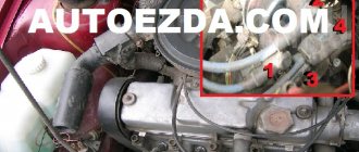
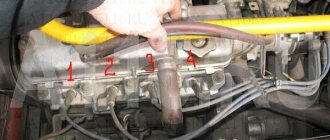
On the engine itself, the cylinder numbering goes from the location of the timing belt to the starter, that is, from left to right. The fourth cylinder is closest to the starter, and the first is closest to the timing belt. When connecting, it is important to look at which socket of the distributor cover the wire comes from, if you confuse their location, the car will not start.
If you have connected the wires correctly, but the car still does not start, then the problem may be in them. Check high-voltage conductors for integrity. If you haven't changed them in a while, it's worth buying a new set. The peculiarity of these wires is that over time microcracks can form on their surface. They lead to a lack of spark when the ignition distribution system is working. Moisture and dust get into these cracks, which damages the wire from the inside, although it appears intact from the outside.
Numbering of cylinders in different types of internal combustion engines
As for the standards for numbering combustion chambers, there are none. The way they are numbered in the internal combustion engine is influenced by the following factors:
- Type of drive;
- ICE type, block layout;
- Transverse or longitudinal arrangement of the unit under the hood;
- Side of rotation.
On standard front-wheel drive cars with a transversely mounted engine, the numbering begins on the timing side. So, near the timing belt there is the first cylinder and then all the others. The latter is located near the checkpoint.
Examples
In multi-cylinder V-twin engines, the first cylinder is located in the bank on the driver's side.
In American-made engines, the combustion chambers and their numbering may differ and defy logic.
So, for in-line fours and sixes, the first cylinder may be near the radiator, while on all other models the numbering begins towards the interior. If the numbering is reversed, then the cylinder closest to the passenger compartment is considered first.
Note: How to remove a hernia on a car wheel and why it is dangerous
The French are very original and use two methods of numbering the combustion chambers of internal combustion engines.
- On inline fours, the numbering starts from the flywheel.
- If it is a V-shaped six, then the row closest to the radiator is the first three cylinders, and the row closer to the passenger compartment is the last three.
Website about joints
The ignition module on injection VAZ 2109 is deservedly considered one of the most complex electrical components. If the injectors have a module, then the carburetors have the simplest coil.
The actual, but incredibly important task of the module is the generation of high voltage current, which can reach 30 thousand watts. The current follows high-voltage wires to the spark plugs, which create a spark to ignite the air-fuel mixture.
The classic ignition coil is one of the components of the module, so the system works on a much more complex principle than on carburetors.
Kiel Blinton 05.12.2010 - 17:56
Good day everyone! Forgive me if the topic is button accordion, but there is no one else to ask. Question - I have an engine 2110 engineer, I bought high-voltage wires and foolishly removed the old ones, but I didn’t remember the connection sequence. If I am facing the car, then the numbering of the candles is 1 2 3 4? But how do they all connect to the square ignition module? If anyone knows, please explain or draw a diagram, please.
Attached images
Post edited by Kiel Blinton: 12/05/2010 - 18:03
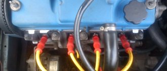
High voltage wires
Often, the main difficulty when repairing a carburetor VAZ 2109 is the reconnection of high-voltage wires that were previously disconnected from the distributor cover. It's also an ignition distributor.
The difficulty is that many people forget the connection procedure or simply do not know. But in practice, returning high-voltage wires is much easier than understanding the ignition module used on the injection VAZ 2109.
By following a few simple rules, you can easily return the wires to their rightful places.
- The ignition distributor cover is installed in its place, that is, on the distributor, only in a single position. Therefore, even if you wanted to, you won’t be able to confuse anything here. Otherwise the lid simply won't fit.
- There is an installation mark on the cover, which indicates the location of the wire socket from the first cylinder.
- The wires must be connected in the following sequence - 1, 3, 4, 2. Move counterclockwise when looking at the distributor cover from the side of the expansion tank.
If for some reason there are no installation marks on the VAZ 2109 carburetor distributor cover, just follow the connection principle shown in the image.
Functionality check
To accurately determine whether it is time to change the high-voltage wires of the VAZ, you need to check their performance with a multimeter.
This operation will take you no more than 15 minutes:
- Turn off the ignition;
- We remove the wires: disconnect the first end from the ignition module, the second from the cylinder;
- We switch the tester to ohmmeter mode and connect the multimeter probes to the wire contacts.
If the high-voltage wires on the VAZ 2114 are in normal technical condition, the multimeter will show a resistance within the value indicated on the wire insulation; if the readings are different, the armored wires on the VAZ 2114 need to be replaced. The process must be repeated on each wire in turn.
If the test shows disappointing results, there is a possibility that the problem of increased resistance lies in oxidized contacts. In this case, you can try to revive the VVP by wiping the contacts with VD-40 or carburetor cleaning fluid.
Also, the cause of problems with ignition can be a breakdown of the GDP. You can determine it visually in the dark - take a flashlight and open the hood of the fourteenth, find and inspect the armored wires, if you notice a slight spark on the insulation - the air intakes are broken and need to be replaced.
Features of the ignition module
Now let's talk about a more complex issue - the ignition module and its design features.
The design includes several components, each of which has its own nuances.
Component
Peculiarities
There are always two coils on a VAZ 2109. This mechanism is responsible for generating current
Switch keys also work together. Through them, the current goes to the spark plugs, plus the controller regulates the time the current is turned on, which is calculated by receiving information from the crankshaft sensor
Electronic control unit
Responsible for distributing information in the form of electronic impulses
High-strength plastic is used for its manufacture, which largely ensures the durability and reliability of the device.
Ignition coil
Location
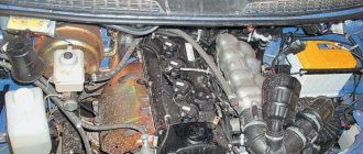
Any work related to repair, testing, and maintenance of the ignition module will be impossible to perform if you do not know basic things - the location of the device.
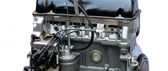
You can find the ignition module (ignition module) in the engine compartment. Find the high voltage wires that go to the spark plugs. One end is connected to them, and the other goes to the module. The MZ is small in size and enclosed in a plastic housing.
Device location
Principle of operation
Initially, on carburetor cars, the system worked due to the presence of an ignition coil. With injectors everything is somewhat different.
- Initially, the ignition coil is turned on, generating a high voltage current. The coil operates on the principle of magnetic induction;
- Then the electronic control unit MZ is connected to the work, performing the functions of control, transmitting commands, and ensuring the flow of current required by the characteristics to the spark plugs;
- Next, the spark plugs activate the spark, ignition occurs, and so on.
MH malfunctions
The ignition module often shows the most basic sign of failure - lack of spark. But this is not the only indicator of a malfunction. These also include:
- Lack of dynamics when accelerating the car. Trying to quickly pick up speed, you can clearly feel failures in engine operation;
- The engine does not produce the usual power; in some cases, the engine is not able to pull the car uphill;
- The idle speed fluctuates;
- One of the pairs of engine cylinders refuses to work. Here, most likely, there is no current that should come from the ignition coil.
To eliminate problems with the MH, the first thing you need to do is check the spark plugs, and then make sure the other elements are working.
VAZ 2110 - modifications
VAZ-21100 . The base model which was produced from 1996 to 2000. The car was equipped with an 8-valve carburetor VAZ-21083 engine with a displacement of 1.5 liters and a power of 69 horsepower.
VAZ-21101 . This modification has been produced since 2004, equipped with an 8-valve gasoline injection engine with a displacement of 1.6 liters.
VAZ-21102. Like the previous modification with an 8-valve injection engine, but with a volume of 1.5 liters.
VAZ-21103 . Modification of the “tens” with a 16-valve injection engine with a working volume of 1.5 liters.
VAZ-21103M . A restyled modification of the VAZ-21103, equipped with a 16-valve petrol injection engine with a displacement of 1.5 liters and a power of 92 horsepower. Produced since 2002.
VAZ-21104 . The modification is equipped with a 16-valve petrol injection engine with a working volume of 1.6 liters.
VAZ-21104M . A restyled modification of the VAZ-21104, equipped with a 16-valve petrol injection engine with a displacement of 1.6 liters. Produced since 2004.
VAZ-21106 GTI . The engine of the VAZ-21106 GTI is the most powerful and expensive modification that has been produced since 2000. The car was equipped with a 2-liter 16-valve Opel C20XE gasoline engine with a capacity of 150 horsepower. The car was fitted with a body kit with swollen arches, and the track was widened by 76 millimeters. It was equipped with R15 wheels with low-profile tires.
VAZ-21106 Coupe . Coupe VAZ-21106 in a coupe body. A distinctive feature of the car was the presence of only two doors, which were lengthened by 250 millimeters, while the body was shortened by 170 millimeters. The engine was installed the same as in the previous VAZ-21106 GTI model.
VAZ 21106 WTCC . A sports modification of the 106 model, it participated in the 2008 FIA WTCC international championship.
VAZ 21107 . Modification of a car for rally competitions. It was equipped with a welded safety cage and a different suspension design.
VAZ 21108 "Premier" . A modification with a body lengthened by 170 millimeters in the rear door area, which provided more convenient entry and exit of passengers. It was equipped with a 1.5-liter injection 16-valve engine.
VAZ 21109 “Consul” . 4-seater luxury limousine based on the VAZ-2110 car. In addition to the length of the body, the dimensions of the rear door were also increased, for more convenient entry and exit of passengers. Equipped with a 1.5 liter engine and R14 or R15 wheels. Overall dimensions: length - 4950 mm, width - 1700 mm, height - 1440 mm. Fuel consumption in the urban cycle is 9.5 liters per 100 kilometers.
Purpose of the distributor cover
The design of the ignition distributor cap (aka distributor) has remained and remains virtually unchanged throughout the entire history of the use of this device as part of the ignition system of gasoline engines:
- On most ignition caps, the contacts for the spark plug wires are marked with numbers that correspond to the serial numbers of the corresponding cylinders
- In addition to protecting the distributor mechanism itself from moisture and dirt, it also serves the purpose of alternating the supply of high-voltage current from the ignition coil winding through high-voltage wires to the spark plugs
- It is because of this narrow specialization that the distributor cap has undergone almost minimal changes along the evolution of all car systems
Let's look at the design and operating principle of this much-needed part.
The distributor cap is a molded part made of non-electrically conductive material (insulator) that has the following device:
- Metal contacts are pressed into this part - these are the side and central electrodes
- The number of side electrodes strictly corresponds to the number of engine spark plugs (but not cylinders, do not forget that there are engines in which there is more than one spark plug for each individual cylinder); the distributor cover on the VAZ 2109 in our case has four side electrodes
- A high-voltage (armor) wire coming from the ignition coil is connected to the central electrode from the outside
- To the side electrodes - high-voltage (armor) wires going to the spark plugs
- Inside the cover itself there is a central contact equipped with a terminal that has a spring-loaded contact element (“carbon”), which transmits voltage to the central (main) contact of the distributor rotor (ignition distributor)
Legend
For ease of maintenance and installation, the electrical wires in the diagrams are made in different colors, identically laid in the car, so that their purpose can be visually determined.
For brevity, colors are indicated by the first letters of the name:
- Blue – “G”;
- Brown – “K”;
- Gray – “C”;
- White – “B”;
- Orange – “O”;
- Yellow – “F”;
- Black – “H”;
- Green – “Z”;
- Pink - "R".
Thanks to the colors, it is easy to determine whether the rein belongs to a particular chain
For reference: the red wire is traditionally used to supply power from the positive terminal of the generator or battery. Therefore, in all diagrams contained in the factory instructions, it is designated by the letter “P”.
The article Wiring diagram for VAZ 21074 injector: understanding the intricacies will also be useful.
The procedure for connecting high-voltage armored wires to the cover on a VAZ 2108-21099
In the process of repairing a car, sometimes it is necessary to disconnect the armor wires from the distributor (see VAZ 2109 distributor device: the difference between contact and non-contact ignition systems and adjusting the ignition timing), while disconnecting these wires, drivers often do not remember the order in which they were connected, which then causes problems with the ignition system, due to the incorrect order of these same wires. Don't despair, our instructions will remind you:
- We list the conditions for correctly connecting the armored wires to the distributor cap:
- It should be remembered that the distributor cover can be installed on the distributor itself in one fixed position; it is simply impossible to confuse anything here
- There is a special installation mark on the cover that will tell you the socket of the wire going to the first cylinder
- The wires are connected to it in the sequence: first, third, fourth, second (we mean the cylinder) in a counterclockwise direction, as if we are looking at this cap from the side where the expansion tank is located.
- To make it clearer, the photo below shows the correct order for connecting the armor wires from the cylinders to the cover
Correct order of connecting armor wires
Now you can connect the armor wires correctly with your own hands.
Maintenance schedule
To avoid having to carry out expensive overhauls of the Lada Samara 2114 yourself, you should follow the manufacturer’s recommendations for servicing the internal combustion engine:
Timing belt replacement after 100,000 km Battery 1 year/20,000 Valve clearance 2 years/20,000 Crankcase ventilation 2 years/20,000 Belts driving attachments 2 years/20,000 Fuel line and tank cap 2 years/40,000 Motor oil 1 year/10,000 Oil filter 1 year/10,000 Filter air 1 – 2 years/40000 Fuel filter 4 years/40000 Fittings and heating/cooling hoses2 years/40000Coolant2 years/40000Oxygen sensor100000Spark plug1 – 2 years/20000Exhaust manifold1 yearIf consumables are replaced within the recommended time frame, the operational life of the internal combustion engine will increase.
Engine control circuit VAZ-21102, 21103
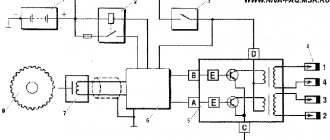
Engine control circuit for VAZ-21102, VAZ-21103 (controller M1.5.4N, “January-5.1”).
1 - injectors 2 - spark plugs 3 - ignition module 4 - diagnostic block 5 - controller 6 - block connected to the instrument panel wiring harness 7 - main relay 8 - fuse connected to the main relay 9 - electric fan relay 10 - fuse connected to electric fan relay 11 – electric fuel pump relay 12 – fuse connected to the electric fuel pump relay 13 – mass air flow sensor 14 – throttle position sensor 15 – coolant temperature sensor 16 – idle speed regulator 17 – VAZ-21102 oxygen sensor 18 – knock sensor 19 – Crankshaft position sensor 20 – canister purge solenoid valve 21 – immobilizer control unit 22 – immobilizer status indicator 23 – vehicle speed sensor 24 – electric fuel pump with fuel level sensor 25 – oil pressure warning lamp sensor 26 – coolant temperature indicator sensor 27 – level sensor oil 28 - phase sensor (installed on a car with a 16-valve engine) A - block connected to the wiring harness of the anti-lock brake system (ABS) B - block connected to the air conditioner wiring harness C - block connected to the electric fan wiring harness D - wires , connected to the ignition switch (backlight lamp) E - block connected to the blue-white wires disconnected from the ignition switch (when installing the immobilizer) F - to the “+” terminal of the battery G1, G2 - grounding points The diagram uses the designation of the element number circuit to which this wire is connected, for example “-4-”. In some cases, in addition to the designation of the element number, it is given through an oblique fraction and the contact number, for example “-5/15-”. The diagram does not show the connection points of the pink-black, red and green with a red stripe wires.
Pinout of 8-pin connector
- power supply
- speed sensor (electric speedometer)
- fuel consumption (for BC)
- coolant sensor
- emergency oil pressure
- check lamp
- oil level sensor
- tachometer signal
Diagram of VAZ 2110 injector 16 valves
1 - headlight 35 - instrument lighting switch 2 - front brake pad wear sensors 36 - ignition switch 3 - reverse light switch 37 - mounting block 4 - engine cooling fan electric motor 38 - recirculation valve switch 5 - sound signal 39 - controller heater 6 - right front door locking motor 40 - hazard warning switch 7 - power window relay 41 - heater control lever illumination lamp 8 - 8 A fuse 42 - glove compartment lighting lamp 9 - starter 43 - glove compartment lighting lamp switch 10 - battery 44 - cigarette lighter 11 - generator 45 - on-board control system display unit 12 - windshield washer motor 46 - ashtray lighting lamp 13 - washer fluid level sensor 47 - brake signal switch 14 - left front door locking motor 48 - locking motor left rear door 15 — power window switch of the left front door 49 — power window switch of the left rear door 16 — coolant level sensor 50 — power window motor of the left rear door 17 — windshield wiper motor 51 — socket for a portable lamp 18 — recirculation valve 52 — clock 19 - micromotor gearbox for heater flap drive 53 - gearmotor for electric window lift on the right rear door 20 - electric motor for heater 54 - power window switch at the right rear door 21 - trunk lock switch 55 - gearmotor for locking the right rear door 22 - power window switch at the right front door 56 - side turn signal 23 - electric window motor of the right front door 57 - parking brake warning lamp switch 24 - door lock system control unit 58 - driver's seat belt sensor 25 - additional heater motor resistor 59 - directional light bulb 26 - brake fluid level sensor 60 - interior light bulb 27 - electric window motor of the left front door 61 — interior air temperature sensor 28 — exterior lighting switch 62 — switch in the front door pillar 29 — instrument cluster 63 — switch in the rear door pillar 30 — rear fog light switch 64 — external rear light 31 — warning lamp fog light 65 - interior rear light 32 - rear window heating indicator light 66 - license plate lights 33 - rear window heating switch 67 - trunk light 34 - steering column switch A - blocks for connecting the rear window washer motor B - blocks for connecting the harness injection system C - to the warning light harness block D - block for connection to the on-board computer E - to the headlight cleaner harness block F - block for connection to the fuel level sensor in the electric fuel pump module G - to the rear window heating element H - block for connecting an additional signal braking J - to the trunk lock motor
See the complete diagram in one file below (click to enlarge):
Electrical circuit of ECM VAZ-21101
1 — VAZ-21101 controller; 2 — block of the ignition system harness to the ABS cabin group harness; 3 — diagnostic block; 4 — immobilizer warning sensor; 5 — immobilizer control unit; 6 — ignition coil; 7 — spark plugs; 8 — nozzles; 9 — electric fuel pump; 10 — block of the ignition system harness to the fuel level sensor harness; 11 — block of the fuel level sensor harness to the ignition system harness; 12 — block of the ignition system harness to the injector harness; 13 — injector harness block to the ignition system harness; 14 — speed sensor; 15 — idle speed regulator; 16 — throttle position sensor; 17 — coolant temperature sensor; 18 — mass air flow sensor; 19 — oil pressure warning lamp sensor; 20 - phase sensor; 21 — oxygen sensor; 22 — crankshaft position sensor; 23 — knock sensor; 24 — solenoid valve for purge of the adsorber; 26 — coolant temperature indicator sensor; 27 — block of the ignition system harness to the instrument panel harness; 28 — block of the instrument panel harness to the ignition system harness; 29 — controller power supply fuse; 30 - ignition relay; 31 - ignition relay fuse; 32 — fuse for the electric fuel pump power supply circuit; 33 — electric fuel pump relay; 34 — electric fan relay; 35 — ignition system harness block to the air conditioner connector; 36 — block of the ignition system harness to the side door harness. 37 — electric fan of the cooling system; 38 — diagnostic connector; 39 — ignition switch; 40 — instrument cluster; 41 — on-board control system unit; 42 — starter relay; 43 — contacts of the 8-terminal blocks of the instrument panel harness and the front harness; 44 — contacts of the 21-terminal blocks of the instrument panel harness and the rear harness; 45 - trip computer.
- A - to the “plus” terminal of the battery;
- B1 — grounding point of the fuel level sensor harness;
- B2, B3 — grounding points of the ignition system harness;
- C - to the starter;
- D - to the driver's door interior lamp switch.