The role of the front suspension
Of course, all the units in a car are important, and they only set it in motion as a whole.
But the topic of our conversation will be the front beam on the VAZ 2110 - its purpose, fault diagnosis, as well as repair or replacement of components. Without suspension, in fact, there would be no way to secure the wheels. It is she who is responsible for the angle at which the wheels will be located, how quickly the tires will wear out, and how quickly the car will run.
You can find out more about wheel bolts here:
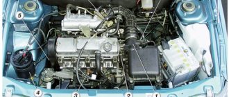
VAZ 2110 front suspension diagram
Beam structure
On the inside, brackets with special holes necessary for installing shock absorbers are attached to the suspension arms. There are also flanges located there, bolted to the axle of the rear wheels and shields located on the brake mechanism. Bushings are attached to the suspension arms on the front side. They are inserted into hinges made of a special rubber-metal material.
Bolts pass through them, connecting the suspension arms together with the stamped-welded brackets. They, in turn, are attached with bolts welded into the side member of the car. The springs of the rear beam of the VAZ 2110 are located in such a way that the first end rests against the recess of the shock absorber, and the second passes through a special gasket directly into the support area attached to the underside of the arch on the car body.
The gasket acts as an insulator and is made of rubber. The shock absorber mounted on the rear suspension is double-acting. It is attached with short bolts directly to a bracket located on the trailing arm in the rear suspension area. In the upper part, fastening is done using the rod method. The rod is fixed in the upper support directly on the suspension spring. The shock absorber is fixed through a protective rubber pad and a support washer.
A double row thrust bearing is located in the middle of the hub. Its structure is very similar to the bearing located in the hub of the front wheels, but it is much smaller in size.
Diagnostics
To diagnose whether everything is in order with the suspension, you need, first of all, to listen to how your VAZ 2110 behaves while driving. This doesn’t even require long distances – for an experienced driver, a couple of kilometers will be enough.
So, let's listen to the suspension:
- You can hear tires squeaking while driving. Moreover, the creaking may not be strong, but it still indicates that the suspension is not all right, and the main reason is that the silent blocks need to be replaced;
- When you hear a creak, be sure to inspect the silent blocks; you may notice cracks or even tears in the rubber;
- And if you hear not a creaking sound, but a knocking sound, it means that the silent blocks of your VAZ 2110 are already fairly worn out, and they simply need to be replaced. These heavily worn parts do not even have enough strength to spin, so instead of sliding, they “slip” and make knocking noises;
- Certain knocking noises can also be caused by the front beam with braces; axial play may occur in them. Such beams are subject to repair, and in particularly advanced cases, complete replacement is necessary.
Diagram of the anti-roll bar on the VAZ-2112
The stabilizer is an important part, but you can drive without it. The absence of a stabilizer is not a reason to remove the car from service.
Stabilizer and traction rod
The unit consists of a rod and two rods. Articles:
- 2110-2906050 – thrust or stand;
- 2110-2906010 – assembly assembly;
- 10516870 – spring washer;
- 2110-2906040 - pillow;
- 10519601 - washer;
- 2108-2906042 - bracket;
- 2110-2906016 – rod;
- 2110-2906078 – upper rod bushing;
- 15971321 – M10 screw;
- 12164711 – nut M10;
- 16104111 – self-locking nut M8;
- 2108-2906079 – lower rod bushing.
To get rid of the stabilizer, remove the parts shown in the list.
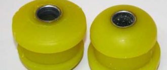
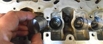
Replacing silent blocks on the front beam
Once you have changed this extremely important part of the front suspension, you will understand that this work does not have to be entrusted to professionals; it is quite possible to carry out the repair yourself. To do this, you need to have a special puller, or make one using two pieces of pipe with washers welded to them. If you don’t understand how to properly make a simple puller, you can either buy it or ask experienced motorists, they probably have it.
On the VAZ 2110, silent blocks are replaced in the following order:
- We “hang” the front wheel using a jack. Be sure to place clamps on both sides under the rear wheels (special shoes or just stones) so that the car does not come off the jack and the beams do not crush you;
- Remove the jacked wheel;
- Check to see if the silent blocks are loose in the beam arm. If they are loose, then that too needs to be repaired;
- Knock out the upper support: first unscrew its nut, turn out the wheel and hit it accurately, but not too hard, on the bipod. This way the support will pop out;
- Remove the upper arm. To do this, unscrew the long bolt of the lever (it is located on top);
- Now you have access to silent blocks. They need to be knocked out with a chisel, hitting them with a hammer. They usually pop out easily on a VAZ 2110, even after one well-aimed blow;
- You need to put a new one in place of the old silent block. This is done by pressing: using a smaller sleeve, the size of the skirt, the larger one is pressed into the lever. For greater sliding ability, you need to clean the old socket, and then wet all parts with soapy water.
After pressing, there should be no play, otherwise the front suspension will still cause you trouble.
Front suspension - complete assembly
The photo shows what the right disc suspension looks like. It is easy to recognize the telescopic post 6, as well as the lever 3. Both of these parts form the basis of the assembly.
Suspension parts assemblies
We list the main parts in ascending order of number: 1 – anti-roll bar; 2 – stabilizer rod; 3 – suspension arm; 4 – ball joint; 5 – steering knuckle; 6 – suspension strut; 7 – stretch (saber); 8 – extension bracket.
Parts 7 and 3 could constitute a "monolith". But even then they would be mounted on hinges, and in the suspension design of the VAZ-2112 (and 2110) we will find these hinges plus one more - it connects parts 3 and 7.
The photo does not show the swing arm, but here it is attached to the shock absorber, that is, it is part of it.
The main part is a strut with a shock absorber
Everything that is indicated above by the number 6 consists of several parts. Let's list them.
Strut
The numbers indicate the elements:
- 2108-2901056 – metric nut M14;
- 2110-2902760 - cup;
- 10519601 - washer;
- 16105021 – self-locking nut M12;
- 2110-2902816 – bump stop;
- 2110-2905003 and 2110-2905002 – shock absorber left and right;
- 2110-2902826 - frame;
- 2108-2901052 – washer for screw;
- 15540931 – M12 screw (until 07.2001);
- 2108-2901051 – lower screw (after 07.2001);
- 2110-2901054 – cap;
- 2110-2902842 - washer;
- 2110-2902830 – screw;
- 2110-2901032 - washer;
- 2110-2902820 – upper support (pillow);
- 2112-2902712 – suspension spring;
- 2112-2901031 and 2112-2901030 – left and right rack;
- 2110-2905681 – anther;
- 2108-2901050 – screw with eccentric;
- 16104111 – self-locking nut M8;
- 2108-2902840 (-01, -02) or 2110-2902840 (-01) – support bearing.
Some station wagons and sedans have racks 2110-2901030 and 2110-2901031. But then springs 2108-2902712 are used. But the parts marked with the number 21 are interchangeable.
Dismantled rack
Rounded fist
Let's consider one important unit, consisting of a minimum number of parts.
Steering knuckle with hub bearing
From the appearance of the unit it is clear what and how it is attached to. Let's list the articles:
- 2108-3103020-01 (-02) – wheel bearing;
- 2108-3103068 – sealing ring;
- 2108-3001060 – dirt protection lining (internal);
- 2108-3103012 – hub;
- 2108-3103079 – bearing element (washer);
- 2108-3103032 – a retaining ring that secures the bearing;
- 2108-3001061 – dirt protection pad (external);
- 2110-3103065 – decorative cap (after 01.2003);
- 2108-3103065 – decorative cap (until 01.2003);
- 2108-3001015 and 2108-3001014 – left and right fist;
- 2108-3103061 – hub mudguard;
- 14044271 – self-locking nut M20.
Lever and everything connected with it
The lower arm holds the ball pin (part 2). The steering knuckle is attached to the ball joint housing. It is not shown in the drawing, but fastening screws 15 are shown.
Levers together with saber stretchers
Let us list the designations:
- 2108-2904046 – rear hinge of the saber;
- 2108-2904185-01 – ball pin;
- 10517070 – spring washer;
- 2110-2904192 – ball joint;
- 15541231 – M12 screw;
- 2108-2904045 – thrust washer;
- 16105011 – self-locking nut M12;
- 2108-2904040 – swivel joint;
- 2108-2904020 - lever arm;
- 2108-2904270 – saber or stretcher;
- 12638601 - washer;
- 2110-2904070 – casing;
- 2110-2904076 – spacer sleeve;
- 12574921 – self-locking nut M16;
- 15970730 – M10 screw;
- 2108-2904225 – spacer washer (maximum number – 4 pcs.);
- 16101521 – metric nut M12;
- 10516870 - spring washer.
Brackets for attaching sabers are welded to the transverse pipe. That is, on the VAZ-2112 the front suspension contains a “cross member”, and it cannot be excluded from the design.
Cross pipe and fasteners
The photo shows:
- 2112-2904400 – cross pipe;
- 2108-2904050 – saber front hinge;
- 12574921 – nut M16;
- 2110-2904436 – cap-plug;
- 2108-2904054 – front joint washer (up to 12.2000);
- 2110-2904054 – the same (after 12.2000);
- 2108-2904225 – spacer washer (maximum number – 2 pcs.);
- 2110-2904055 - washer;
- 2110-2904312 – screw.
Some sedans and station wagons have a cross pipe 2110-2904400 (-01).
And now the procedure for replacing the silent block:
1. Unscrew the fastening nuts from the bolts of the stern beam, remove the retaining bracket on the left and disconnect the control brake rod. 2. We release the bolt from the technological hole and slightly raise the vehicle on a jack, moving the beam eye to the lower plane. We use a wooden beam as a spacer between the body surface and the rear beam. 3. Press out the silent block of the rear beam using a puller or drift. 4. We lubricate the working surfaces of the product and the eye with a solution that facilitates its installation, and press the product into place. 5. We take out the beam, use another jack to coaxially install the rear installation beam eye with the bracket and secure it with fasteners. 6. We tighten the stern beam fasteners on the car removed from the lifting mechanisms.
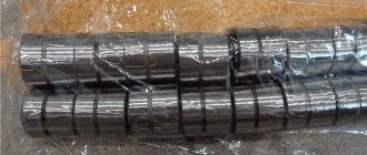
The selection of rear beam silent blocks for the VAZ 2110 is carried out in accordance with the item number 2110-2914054. The fundamental difference between these products and similar spare parts from the VAZ model range is the size of the outer diameters of the product. The standard silent block of the rear beam, which can be replaced on an electric lift or on an overpass or driver's pit, is purchased at auto stores using the appropriate catalog code.
Watch the video:
- < Central locking for VAZ 2106 and its installation
- What is the best way to replace the rear struts of a VAZ 2110 >
Removing the rear block
Replacement of the rear beam is carried out after transporting the car to an inspection ditch or lift. To begin, remove the brake pads located at the rear of the VAZ 2110. Disconnect the steel ropes that secure the parking brake to the underside of the beam attached to the rear of the bracket.
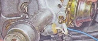
Now disconnect the thin brake hoses leading to the brake cylinders located at the rear of the car. Disconnect the brake pipes attached to the beam. In addition, you will need to disconnect the elastic lever from the beam, which is located on the drive responsible for regulating the pressure.
Using a size 17 wrench, unscrew the 4 mounting bolts holding the hub axle together with the rear suspension beam. Remove the axle itself along with the brake mechanism shield and, if necessary, separate them by unscrewing the two fastening screws using a Phillips screwdriver. Bend the bracket and remove the brake pipe.
It is necessary to disconnect the lower ends of the shock absorbers and the nuts attaching the beams to the brackets from the beam. After this, you need to remove the bolts from the beam and carefully remove it. Using a size 17 socket, remove the 3 nuts securing the bracket to the body.
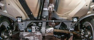
Rear suspension structure: 1 — rubber-metal hinge; 2 — suspension arm mounting bracket; 3 — shock absorber casing; 4 — compression stroke buffer; 5 — casing cover; 6 — support washer; 7 — shock absorber cushion; 8 — spacer sleeve; 9 — shock absorber; 10 - insulating gasket; 11 — rear suspension spring; 12 — lever connector; 13 — rear suspension beam arm; 14 — shock absorber mounting bracket; 15 - flange; 16 — lever bushing